Table of Contents
Advertisement
Quick Links
Advertisement
Table of Contents
Troubleshooting

Related Manuals for Generac Power Systems MAGNUM


Summary of Contents for Generac Power Systems MAGNUM
- Page 1 Self-Prime Diesel Trash Pump Owner’s Manual MTP4DZD • MTP4DZV • MTP6DZD • MTP6DZV 002073 MODEL NUMBER: _________________________ SERIAL NUMBER: _________________________ DATE PURCHASED:________________________ www.discount-equipment.com SAVE THIS MANUAL FOR FUTURE REFERENCE...
- Page 2 We sell worldwide for the brands: Genie, Terex, JLG, MultiQuip, Mayco, Toro/Stone, Diamond Products, Magnum, Airman, Mustang, Power Blanket, Nifty Lift, Atlas Copco, Chicago Pneumatic, Allmand Brothers, Essick, Miller Spreader, Skyjack, Lull, Skytrak,...
- Page 3 WARNING California Proposition 65. Engine exhaust and some of its constituents are known to the state of California to cause cancer, birth defects, and other reproductive harm. (000004) WARNING California Proposition 65. This product contains or emits chemicals known to the state of California to cause cancer, birth defects, and other reproductive harm.
-
Page 4: Table Of Contents
Table of Contents Section 1 Introduction and Safety Analog Transducer/Switch Gauge ......22 Digital Transducer Gauge .........22 Introduction ..............1 Active Alarms .............22 Safety Rules ..............1 Alarm List ..............22 General Hazards ............1 Configuration Menu ...........22 Explosion and Fire Hazards ........2 Display Menu ..............23 Trailer Hazards .............2 Units Menu ..............23 Battery Hazards ............2... - Page 5 Settings Menu ............29 Checking the Oil Level Sight Gauge (Diaphragm Pump Only) ..........45 Governor ..............29 Changing the Engine Oil ........... 45 CP750 CAN Add ............29 Changing the Oil Filter ..........45 Calibrate RPM ............29 Aux Output ..............30 Adding Coolant ............
- Page 6 Table of Contents Section 5 Troubleshooting Crankshaft Removal and Installation ..............56 Pump Troubleshooting Guide ........59 Removal ..............56 Engine Fault Shutdown Troubleshooting ....60 Installation ..............57 Control System Troubleshooting ......61 Crankshaft Lip Seal Removal and Installation ..57 Diagnostic Trouble Codes (DTS) ......61 Roller Bearing Removal and SPN Codes ..............61 Installation ..............57...
-
Page 7: Section 1 Introduction And Safety
Introduction and Safety Section 1 Introduction and Safety Introduction DANGER Thank you for purchasing a Generac Mobile Product. This unit has been designed to provide high- Indicates a hazardous situation which, if not avoided, performance, efficient operation, and years of quality will result in death or serious injury. -
Page 8: Explosion And Fire Hazards
Introduction and Safety WARNING WARNING Moving Parts. Keep clothing, hair, and Verify unit is properly secured with wheel appendages away from moving parts. Failure chocks and on level ground. Failure to do so to do so could result in death or serious injury. could result in death or serious injury. -
Page 9: Pump Hazards
Introduction and Safety Pump Hazards Reporting Trailer Safety Defects If you believe your trailer has a defect which could cause WARNING a crash or could cause injury or death, you should imme- diately inform the National Highway Traffic Safety Admin- Personal Injury. -
Page 10: Section 2 General Information
General Information Section 2 General Information Unit Dimensions 002132 Figure 2-1. Unit Dimensions MTP4DVD MTP4DVZ 75.00 in (1.905 m) 73.88 in (1.877 m) 150.12 in (3.813 m) 98.00 in (2.489 m) MTP6DVD MTP6DVZ Specifications are subject to change without notice. Owner’s Manual for Dry-Prime Diesel Trash Pumps... -
Page 11: Unit Serial Number Locations
General Information Unit Serial Number Locations 002291 Figure 2-2. Serial Number Locations Safety Decal Locations NOTE: Locations may vary slightly from unit to unit. Description Description General safety: keep hands clear of belt, hot surfaces, Beware of moving blades and fan, and do not remove guard Float switch port location Suction port location Do not step... - Page 12 General Information Owner’s Manual for Dry-Prime Diesel Trash Pumps...
- Page 13 General Information Owner’s Manual for Dry-Prime Diesel Trash Pumps...
-
Page 14: Component Locations
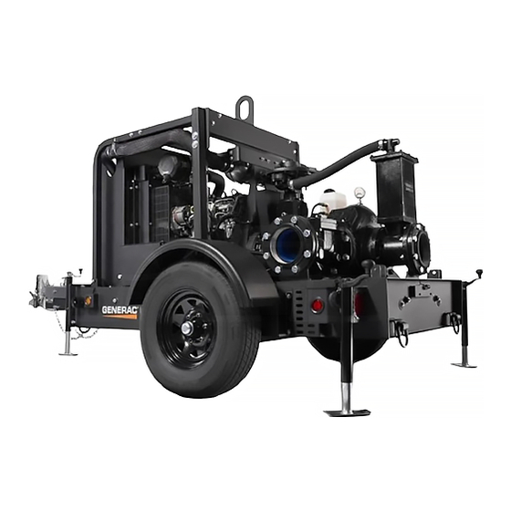
General Information Component Locations 002073 Figure 2-3. Left Side (6 Inch DZV Pump Shown) Air cleaner Battery Central lift point Fuel filter (main) Rear leveling jacks (2) Coolant drain Priming chamber Engine oil dipstick Pump inlet (suction) port Engine oil filter Pump outlet (discharge) port Front leveling jack Fuel pre-filter... - Page 15 General Information 002130 Figure 2-4. Right Side (6 Inch DZV Pump Shown) Mechanical seal oil reservoir Control panel Compressor Fuel fill port Tie down rings Radiator sight glass Rear leveling jacks Emergency stop switch Fuel tank drain Manual holder Owner’s Manual for Dry-Prime Diesel Trash Pumps...
- Page 16 General Information 002333 Figure 2-5. Venturi-Prime Pump Components - Left Side (4 Inch Shown) Belt and guard Suction cover Compressor Volute Compressor output fitting Backplate Compressor hose Mechanical seal Mechanical seal oil reservoir Frame bracket Relief valve Grease fittings Venturi fitting Bearing frame Priming chamber Compressor bracket...
- Page 17 General Information 002334 Figure 2-6. Diaphragm Vacuum Pump Components - Left Side (4 Inch Shown) Diaphragm vacuum pump Run dry gland Air discharge hose Grease fittings Mechanical seal oil reservoir Frame Priming chamber Shaft and Drive end shaft key Suction spool Belt and guard Volute Owner’s Manual for Dry-Prime Diesel Trash Pumps...
-
Page 18: Trailer Tongue Preparation For Use
General Information Trailer Tongue Preparation for Use If the unit is shipped with the trailer tongue in the upright Figure 2-10. Remove the upper bolt, nut, and position, follow the steps below to lower the tongue. washers (F) to allow the tongue to pivot. Figure 2-7. -
Page 19: Hood Operation
General Information Hood Operation 002312 Figure 2-13. Hood Latches NOTE: Pump enclosures are optional. To close the rear hood: Verify all contact surfaces for hood are clean of To open the rear hood: debris. Stand at the rear of the unit and firmly grasp the Verify there is proper clearance to accommodate handle at the rear of the hood and slowly tilt the swing of hood to the full-open position. -
Page 20: Welding On Equipment With Electronic Controls
General Information Welding on Equipment with Stop the engine. Turn the Key switch to the OFF position. Electronic Controls Disconnect the negative (-) battery cable from the Proper welding procedures are required to avoid damage battery. to electronic controls, sensors and associated compo- Open any installed Battery Disconnect switch. -
Page 21: Section 3 Operation
Operation Section 3 Operation Control Panel Operation NOTE: ECU programming determines the response to warnings and failures. Typically the ECU can be Turning the Key switch to the RUN position energizes the programmed to shut down, derate, or run to failure. The ECU (Engine Control Unit), illuminates all LED indicators CANplus display only displays ECU reported conditions. -
Page 22: Ramp Throttle (Speed Control Switch)
Operation to fall below the ECU minimum or exceed the maximum ing as indicated by the Auto Standby LED. RPM. For electronically governed units, once the configured automatic start condition exists, the display powers up, the NOTE: To change the minimum requested RPM and panel starts the engine and follows the throttle control maximum requested RPM settings, contact Generac profile configured (see... -
Page 23: Start And Stop Events
Operation Start and Stop Events The start and stop events are determined by the Start and Stop Functions: combination of START and STOP mode and function. Empty Uses the selected mode to reduce the level or pressure. Start and Stop Modes: Fill Single Switch Uses the selected mode to increase the level or pres-... -
Page 24: Dead Band
Operation Digital Controller Dead Band In some situations, the transducer level may fluctuate A graphical menu is displayed when any button from 1 to around the Target Set Point. To limit throttle hunting using 4 of the five soft buttons is pressed. The menu structure the maintain functions, a dead band can be programmed. -
Page 25: Analog Gauge Pages
Operation Analog Gauge Pages any supported parameter. Refer to for a complete list of available parameters. Analog Gauge Pages provide four independent pages of Adjust mode can be disabled in the Configuration menu analog gauges. To enable Analog Gauge Pages, press any (Quad Adjust - Off) to prevent accidental changes. -
Page 26: Analog Transducer/Switch Gauge
Operation NOTE: Gauge selections are limited to the data currently NOTE: Standard J1939 abbreviations are used for being received. alarms. MS = Most Severe, MOD= Moderately Severe, LS = Least Severe. Analog Transducer/Switch Gauge Refer to Diagnostic Trouble Codes (DTS) for more infor- mation on SPN/FMI codes. -
Page 27: Display Menu
Operation Units Menu This menu allows the user to set the units used for speed, distance, pressure, volume, and temperature inde- pendently. Button 4 cycles through the available values for the selected item. Figure 3-12. Configuration Menu Figure 3-15. Units Menu Speed MPH (miles per hour);... -
Page 28: Max Rpm
Operation The message is displayed on each power up until the elapsed timer is disabled or reset. NOTE: It is not possible to set the service timers if engine hours are not being received by the display Figure 3-17. Gauges Menu Max RPM Sets the full scale RPM indicated by the tachometer gauge. -
Page 29: Com Viewer
Operation The default settings are: Setting Metric Language English Button Beep Service Timers Display Mode Analog Gauges Figure 3-22. J1939 Viewer Menu Gauge Pages Defaults Quad Adjust Button 1 freezes the display while button 2 shows Stop Stats the CANbus data statistics screen. Demo Mode 0 (Off) Engine Source... -
Page 30: Engine Source
Operation Engine Source PIN Entry Selects which source the display listens to for gauge data. This menu allows the user to turn PIN Entry on or off. To Every device on a J1939 network has a unique address enable the PIN Entry feature, select PIN Settings and press (in the range 0-254) to which the display can choose to button 4 to enable. -
Page 31: About
Operation CONFIG Generac programmed controller part number ADAPTER Last adapter serial number used to program the controller Figure 3-30. PIN Change - Awaiting Confirmation VERS Software version number If the new PINs match, a confirmation screen is PRODUCT Controller model name displayed. -
Page 32: Idle Rpm
Operation Warm Up s Selects the number of seconds to operate at idle speed before beginning the ramp to intermediate speed. The warm-up time begins when the starter is disengaged. Ramp Up s Selects the number of seconds to ramp from idle speed to intermediate speed after warm-up. -
Page 33: Starter
Operation Settings Menu This submenu allows the user to configure CANplus hard- ware. Figure 3-38. Transducer Type Menu Range Selects appropriate range for the transducer type. Figure 3-40. Settings Menu High Set Point Governor For Empty and Maintain Out modes, sets the level that begins and autostart cycle. -
Page 34: Aux Output
Operation Telemetry Menu NOTE: Calibrate RPM is only available on mechanically governed engines. The RPM must be calibrated for This menu allows configuring the optional telemetry system. automatic start and stop operation to function. Crank the engine and measure the engine RPM with a hand-held tachometer. -
Page 35: Db Viewer
Operation DB Viewer NOTE: Incorrectly configuring the Engine Source address will result in no data available for display. The Database Viewer displays and decodes all data mon- itored by the display. This diagnostic tool allows viewing Data Not Available data not normally displayed. The list can be scrolled using buttons 1 and 2 Gauges and the Db Viewer will display... -
Page 36: Data Parameters Monitored
Operation Data Parameters Monitored This table lists the engine and transmission parameters that are monitored via the CANbus. The parameters can be displayed by the user-configurable gauge pages or the single analog gauge. DB is an abbreviation for the internal database which stores all data transmitted from the engine/transmission. - Page 37 Operation Icon Parameter Gauge Pages Single Gauge Database Transmission Oil Pressure Clutch Pressure Air Start Pressure Injector Control Pressure Temperature (ºC, ºF) Engine Coolant Temperature Engine Intercooler Temperature ...
-
Page 38: Pump Set Up
Operation Icon Parameter Gauge Pages Single Gauge Database Time (h) Total Engine Hours Trip Engine Hours Service Hours Miscellaneous Torque Converter Lock-Up Engaged Transducer Current Gear Selected Gear ... - Page 39 Operation screen should be rigid enough to prevent collapse when NOTE: Recommended bell diameters pipe flow is reduced due to clogging. submergences for various flows are shown in Table The table data is referenced from ANSI/HI 9.8-1998. Place the intake hose into the liquid to be pumped. NOTE: The submergence of the suction pipe into the CAUTION liquid should be at least four to five times the pipe...
-
Page 40: Pump Pre-Use Checkpoints
Operation Table 3: Pipe Submergences FLOW (GPM) 1000 1500 2000 2500 3000 3500 4000 4500 Attach a flexible hose/pipe to the outlet (discharge) NOTE: Flexible pipe couplings must be restrained so as side of the pump. not to transmit any strain to the pump flanges when expanding or contracting under pressure. -
Page 41: Starting The Unit
Operation to prime within five minutes, stop it and check the suction CAUTION line for leaks. NOTE: Refer to Throttle Control for information on Equipment damage. Verify proper type and quantity adjusting the pump flow. Several factors can influence of oil prior to starting pump. Failure to do so could pump output: result in pump damage. -
Page 42: Flow Rates
Operation Flow Rates Use the following charts for approximate flow rates. Impeller Dia. Solids Dia. Suction Speed Style Discharge No. vanes Feet x .305 = Meters Inches x 25.4 = Millimeters VARIOUS 8.25"@0° ENCLOSED 3" 2400 4" 4" GPM x .227 = Cubic Meters/Hour GPM x 3.785 = Liters/Minute HP x .746 = KW SINGLE VOLUTE... -
Page 43: Diaphragm Pump System
Operation Diaphragm Pump System • Chevron Turbine Oil GST32 or other ISO viscosity grade 32 or below (synthetic oil recommended) Some pumps are equipped with a diaphragm system. The system is a fully automatic self-priming, dry-prime vacuum • Transmission fluid or hydraulic oil pump. -
Page 44: Emergency Stop Switch
Operation Emergency Stop Switch Connect any trailer wiring to the tow vehicle. Check for proper operation of the directional and brake The unit is equipped with one emergency stop switch. For lights. location of the emergency stop switch, refer to Component Verify all doors and flip hood are properly latched. -
Page 45: Lifting The Unit
Operation Lifting the Unit The tie down rings (B) at the front and back corners of the trailer are intended for tie down use only. Remove the suction and discharge piping from the pump prior to moving. Verify the equipment being used to lift the WARNING unit is in good condition and has sufficient capacity. -
Page 46: Section 4 Maintenance
Maintenance Section 4 Maintenance Normal maintenance, service, and replacement of parts are the responsibility of the owner/operator and, as such, WARNING are not considered defects in materials or workmanship Risk of burns. Do not open coolant system within the terms of the warranty. until engine has completely cooled. -
Page 47: General Maintenance
Maintenance General Maintenance engine operator manual will nullify the warranty, decrease performance and cause equipment damage or premature Refer to the original equipment manufacturer’s operating equipment failure. Maintenance records may be required manual for a complete list of maintenance requirements. to complete a warranty request. -
Page 48: Checking The Oil Level Sight Gauge (Diaphragm Pump Only)
Maintenance Verify the engine is level and check the oil level. WARNING Refer to Checking the Engine Oil. Risk of burns. Allow engine to cool before Changing the Oil Filter draining oil or coolant. Failure to do so could result in death or serious injury. NOTE: The filter cartridge should never be pre-filled. -
Page 49: Top-Wind Models
Maintenance Top-Wind Models compression and collapsing the three sections together. Use care not to drill into the volute • Apply a lightweight oil to the screw stem. casting. Better control is obtained if small pilot holes are first drilled and then enlarged to “cut” the ring. - Page 50 Maintenance 002307 Figure 4-2. 4 Inch Pump Cross-Section 1. Shaft key 11. Wear ring 2. Lip seals (3) 12. Priming chamber 3. Shims 13. Impeller lockscrew 4. Frame 14. Impeller washer 5. Breather 15. Mechanical seal 6. Mechanical seal oil reservoir 16.
-
Page 51: Pump Assembly
Maintenance 002308 Figure 4-3. 6 Inch Pump Cross-Section 1. Shaft key 12. Priming chamber 2. Lip seals (3) 13. Wear ring 3. Shims 14. Impeller lockscrew 4. Frame 15. Impeller washer 5. Breather 16. Impeller shims 6. O-ring (sleeve) 17. Mechanical seal 7. -
Page 52: Impeller Lockscrew Installation
Maintenance For seals, bring the gland and gasket against the capscrews. Stainless steel lockscrews are supplied with face at the seal chamber and tighten the bolts Loctite 262, which should be applied to lockscrew threads evenly. and shaft prior to installation. First determine the size and material of the lock, then Impeller Lockscrew Installation torque to the appropriate value listed in the table below. -
Page 53: Assembly
Maintenance Assembly ambient temperatures, exposure to contamination and moisture, seasonal or continuous operation and other Press the drive end and pump end bearings onto factors. The brief recommendations which follow are the shaft. Pressure should be applied to the inner general in nature and must be coupled with good judgment race. -
Page 54: Removing The Mechanical Seal
Maintenance gland would indicate a damaged or worn lip seal. Refer to portion of the seal may now be seen. Slide off the seal Mechanical Seal for oil recommendations. spring. Lubricate the shaft and remove the reminder of the rotating portion, being careful to avoid damaging the primary seal. -
Page 55: Priming Chamber
Maintenance Install the impeller. Verify that the spring slides over NOTE: The tow actuator arms are very similar in appear- impeller pushes against ance. Before removing either of these parts, make spe- backshroud of the impeller. cial note of their position and direction in relationship to other assembly parts. -
Page 56: Discharge Check Valve
Maintenance the valve seat. Also check the prime valve for any dam- as well as with pipe size. To determine the extent of the age or debris. addition for a specific performance point, refer to the flow rate charts. See Flow Rates. -
Page 57: Diaphragm Pump System
Maintenance Lay the cover gasket and cover over the bolt holes Disconnect the lower oil line at the reservoir, hold and disc hinge. the disconnected end over a container and move the line and container down to below the Insert the lubricated bolts, noting that the bolts in connected end of the oil line. - Page 58 Maintenance 002311 Figure 4-6. Vacuum Pump Cross-section Valve stud ocknut Suction and exhaust valve Lock washer Actuator valve Crankshaft bearing O-ring (pedestal) top cock Actuator neck seal Connecting rod Actuator shaft Fulcrum pin Grease relief valve Fulcrum pin bearing Actuator shaft bearing Internal lip seal Pedestal bearing Wiper lip seal...
-
Page 59: Assembly
Maintenance Assembly Remove the four 3/8 in. nuts. Remove the suction valve elbow and discard the Install the vacuum pump support table and oil res- gasket. ervoir. Lift the valve over the head of the valve stud; do Orient the oil reservoir so that the inlet and outlet not remove the bolt. -
Page 60: Crankshaft Lip Seal Removal And Installation
Maintenance Remove the inspection cover. Remove and discard Carefully lower the pedestal, complete with seal O- gasket. ring and linear bearing, over the actuator shaft. (Assembly tool [P/N: 52655] is available to assist Remove thumbscrew dippers from with reassembly of the pedestal without damage to crankshaft. -
Page 61: Pedestal Bearing And Seals Removal And Installation
Maintenance Pedestal Bearing and Seals Removal Protect the unit from blowing sand and dirt. and Installation Stack no other items on top of the pump/ equipment. Remove the vacuum pump pedestal assembly, Protect the unit from the entry of any animals. complete with lip seals, following the steps in Crankshaft Removal and Installation. -
Page 62: Section 5 Troubleshooting
Troubleshooting Section 5 Troubleshooting Pump Troubleshooting Guide Symptom Possible Cause No discharge 1,2,3,4,5,7,8,9,10,17,18,19,20,37 Reduced capacity 2,3,4,5,7,8,9,10,11,17,19,20,21,38,39,40,47 Reduced pressure 5,7,8,11,13,18,19,38,39,40,47 Loss of prime 2,3,4,7,10,11,20,21,22,23 Power consumption excessive, engine runs hot 6,12,13,17,18,19,24,33,34,35,36,37,38,41,42,43,44 2,4,9,10,14,15,17,26,27,28,29,30,31,32,33,34,35,36, Vibration and noise 39,40,41,42,43,44,48 Seal: excessive leakage, short life, seal housing 22,23,25,33,34,35,36,41,44,45,46 overheating Bearings: overheating, short life, noise... -
Page 63: Engine Fault Shutdown Troubleshooting
Troubleshooting Engine Fault Shutdown Troubleshooting Symptom Possible Cause Solution Check oil level, replace as neces- Low oil level sary Faulty oil pressure sender Replace oil pressure sender Low oil pressure shutdown Change engine oil, refer to engine Incorrect oil grade operating manual Worn oil pump Refer to engine operating manual... -
Page 64: Control System Troubleshooting
Troubleshooting Control System Troubleshooting Symptom Possible Cause Solution Faulty connection to battery Correct battery connections Control system does not perform self test Faulty control system Repair or replace control system Correct ECU stop condition, use Control system shuts down Engine stop LED illuminated ECU diagnostics Turn on key, verify display plugged Display lost power... -
Page 65: Fmi Codes
Troubleshooting FMI Codes FMI codes are defined by SAE J1939-71. Refer to ECU documentation for correct interpretation of FMI codes for a specific SPN. Table 9 - FMI Codes Description Data valid but above normal operational range Data valid but below normal operational range Data erratic, intermittent or incorrect Voltage above normal or shorted high Voltage below normal or shorted low... -
Page 66: Section 6 Installation Diagrams And Service Log
Installation Diagrams and Service Log Section 6 Installation Diagrams and Service Log DC Wiring Diagram 90563_D_01.26.15 Owner’s Manual for Dry-Prime Diesel Trash Pumps... -
Page 67: Trailer Lights Wiring Diagram
Installation Diagrams and Service Log Trailer Lights Wiring Diagram 54017 Owner’s Manual for Dry-Prime Diesel Trash Pump... -
Page 68: Service Log
Installation Diagrams and Service Log Service Log OIL GRADE: _____________________________________ BRAND: __________________________________ COOLANT MIXTURE: _____________________________ BRAND: __________________________________ __________________________________________________________________________________________ __________________________________________________________________________________________ __________________________________________________________________________________________ __________________________________________________________________________________________ __________________________________________________________________________________________ __________________________________________________________________________________________ __________________________________________________________________________________________ __________________________________________________________________________________________ __________________________________________________________________________________________ Hours to Coolant Hours to Coolant Date Oil Level Date Oil Level Service Level Service Level Owner’s Manual for Dry-Prime Diesel Trash Pumps... - Page 69 www.discount-equipment.com Part No. 54095 Rev. A 06/20/16 © Generac Mobile Products. All rights reserved Specifications are subject to change without notice. No reproduction allowed in any form without prior written consent from Generac Mobile Products.