Table of Contents
Advertisement
Quick Links
Advertisement
Table of Contents

Related Manuals for EAW PROFESSIONAL RS121


Summary of Contents for EAW PROFESSIONAL RS121
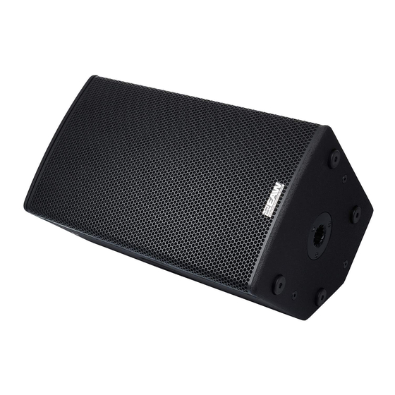
- Page 1 RS Series User Manual...
-
Page 2: Important Safety Instructions - Read This First
IMPORTANT SAFETY INSTRUCTIONS - READ THIS FIRST Safety Instructions Read and heed all warnings and safety instructions in this manual before using this product. Failure to follow these precautions may result in damage, injury, or death. 1) Read these instructions. 2) Keep these instructions. -
Page 3: Fcc Compliance
CAUTION: Changes or modifications not expressly approved by EAW could void the user's authority to operate the equipment. The normal function of the product may be disturbed by Strong Electro Magnetic Interference. If so, simply reset the product to resume normal operation by following this instruction manual. -
Page 4: Table Of Contents
Adjusting the Output Level ..........................16 Onboard Processing & Voicing ..........................16 Voicing Options..............................16 Main ................................. 16 Monitor ................................16 EAW DSP Innovations .............................. 17 DynO™ ................................17 EAW Focusing™ ............................... 17 RS Application Configurations ..........................18 Rotating the horn ............................18 Application Notes .............................. - Page 5 Electrical Warnings ..............................23 AC MAINS SUPPLY ............................... 23 Operating Temperature............................23 General Service ..............................24 Rigging Service ..............................24 Routine Maintenance ............................24 Internal Electronics and Wiring ........................... 24 Contacting EAW ............................... 25 Operating Questions ............................25 Service Information ............................. 25...
-
Page 6: Rs™ System Overview
RS™ System Overview RS is the newest powered point‐source loudspeaker from EAW. Drawing from EAW’s rooted legacy as a manufacturer of high‐end touring loudspeakers, RS is designed specifically for the professional audio users in corporate AV, rental & staging, and installation. RS Series consists of four two-way, point source models (RS121, RS123, RS151, &... -
Page 7: Rs Subwoofers
RS Subwoofers... -
Page 8: Unpacking
Although EAW will help in any way possible, it is always the responsibility of the receiving party to file any shipping damage claim. The carrier will help prepare and file this claim. -
Page 9: Functions And Operations
Functions and Operations RS 121, 123, 151, 153 Rear Input Panel Diagram 1. Level (Gain) Control Adjusts the level of the INPUT signal. Turning counterclockwise will reduce the output level and turning clockwise will raise the overall output level of the speaker. 2. - Page 10 The limit indicator will turn red when the output has reached its maximum level. If the LED blinks occasionally, EAW DynO™ will optimize the output and continue to provide clear output at its maximum volume. If the LED blinks frequently or is lit continuously, reduce the level control (1) to prevent output distortion.
-
Page 11: Rs115 Rear Input Panel Diagram
RS115 Rear Input Panel Diagram 1. Level (Gain) Control Adjusts the level of the INPUT signal. Turning counterclockwise will reduce the output level and turning clockwise will raise the overall output level of the speaker. 2. XLR Input Connector Two balanced XLR input connectors for analog input signal. 3. - Page 12 The limit indicator will turn red when the output has reached its maximum level. If the LED blinks occasionally, EAW DynO™ will optimize the output and continue to provide clear output at its maximum volume. If the LED blinks frequently or is lit continuously, reduce the level control (1) to...
-
Page 13: Rs118 Rear Input Panel Diagram
RS118 Rear Input Panel Diagram 1. Level (Gain) Control Adjusts the level of the INPUT signal. Turning counterclockwise will reduce the output level and turning clockwise will raise the overall output level of the speaker. 2. XLR Input Connector Two balanced XLR input connectors for analog input signal. 3. -
Page 14: Audio Connections
The limit indicator will turn red when the output has reached its maximum level. If the LED blinks occasionally, EAW DynO™ will optimize the output and continue to provide clear output at its maximum volume. If the LED blinks frequently or is lit continuously, reduce the level control (1) to prevent output distortion. -
Page 15: Ac Mains Connection
The TRS wiring convention is as follows: Pin 1: Shield Pin 2: +/Hot Pin 3: -/Cold AC Mains Connection Connect the supplied AC mains cord to the IEC connector (RS 121/151 Models) or Neutrik® powerCON® socket (RS 123/153 Models) on the rear of the loudspeaker. Connect the other end to an AC mains supply receptacle, nominally 115V 60Hz or 230V 50 Hz as labeled on the loudspeaker. -
Page 16: Operating Indicators
CAUTION: Electronic limiters cannot provide absolute protection against driver failure. Thus, if limiting is occurring, it is a warning that excessive signal levels are being approached. EAW is not responsible for damaged or broken speaker components due to user error. -
Page 17: Adjusting The Output Level
Adjusting the Output Level -∞ Starting with the input level attenuator at (all the way to the left), turn the input attenuator up until the desired volume is reached, but below the point where the Limiter light illuminates. Onboard Processing & Voicing Voicing Options RS features two distinct voicings on two-way to accommodate select applications. -
Page 18: Eaw Dsp Innovations
EAW DSP Innovations DynO™ DynO™ is a revolutionary processing technique that allows EAW Engineers to maximize output from a given amplifier – transducer combination. As opposed to conventional limiting which simply views amplifier output and driver power handling in aggregate (i.e. a driver can handle 100 watts or an amplifier can produce 500 watts), the DynO process involves much more detail and complexity. -
Page 19: Rs Application Configurations
RS Application Configurations Rotating the horn RS products feature a user-rotatable horn, providing exceptional application flexibility and the ability to maintain the 90 x 60 coverage pattern when the speaker is mounted horizontally. To rotate the horn, please follow the steps outlined below. 1. -
Page 20: Application Notes
orientation of the horn throat opening. When the opening is in the vertical orientation, the horn is in the default 90 x 60 configuration. If the opening is horizontal, the horn is in the 60 horizontal x 90 vertical orientation. Application Notes Flying RS from threaded mounting points RS products attachment points are designed to accept M10 hardware. -
Page 21: Rigging
Rigging RS series products are intended to be suspended via integral rigging points, or ground-stacked. RS subwoofers are intended to be ground-stacked only. It is the user’s responsibility to determine the viability and safety for alternate methods and implement them accordingly. NOTE: At a minimum, any suspended RS loudspeaker must be flown from the two top M10 rigging points. -
Page 22: Basic Field Troubleshooting & Repair
Basic Field Troubleshooting & Repair Issue Potential Causes Potential Solutions Speaker is not connected to Connect speaker to power source using a properly- a power source rated power cable. Power Won't Turn Speaker power cable is not Swap power cable with a known-good cable. connected properly or faulty. -
Page 23: Rigging Problems
Microphone producing a feedback loop. Reduce microphone gain. If the suggested solutions do not fix the problem, please contact EAW Applications Engineering (see final page of manual for contact.) Rigging Problems Because of the potential serious consequences and liabilities due to faulty rigging, contact... -
Page 24: Powered Loudspeaker Electronics
3. Poor frequency response, such as the loss of low or high frequencies 4. Intermittent sound 5. Excessive electronic noise In the case of malfunctioning electronics, contact the EAW Parts Department for troubleshooting and repair instructions. Internal Electronics and Wiring Faulty electronics are serviced by replacing the entire amplifier module. -
Page 25: General Service
SERVICEABLE. Internal Electronics and Wiring The RS Amplifier Module is not user-serviceable and must be sent to EAW for repair. In the unlikely event of a failure of any amplifier or processing components, simply remove and replace the entire Amplifier Module with a spare. -
Page 26: Contacting Eaw
Contacting EAW We have attempted to make this manual as thorough as possible. However, feel free to contact us with any further questions or comments for topics not covered. Operating Questions EAW Applications Engineering 508-234-6158 800-992-5013 (USA only) e-mail design@eaw.com Service Information EAW®... - Page 27 2. Shipping products must be properly packaged. Where possible, use the original shipping carton and packing materials. If the original shipping carton cannot be used, contact EAW to send you a new carton, for which there will be a small charge.
- Page 28 Eastern Acoustic Works One Main Street Whitinsville, MA 01588 tel 800 992 5013 / +1 508 234 6158 www.eaw.com ©2021 Eastern Acoustic Works All rights reserved. Products are not drawn to scale. All terms, conditions, and specifications subject to change without notice.