Table of Contents
Advertisement
Quick Links
Instruction Manual
D103460X012
Fisher
D3 Control Valve with easy-Drive
™
Actuator
Contents
. . . . . . . . . . . . . . . . . . . . . . . . . . . . . . . . .
. . . . . . . . . . . . . . . . . . . . . . . . . . . . .
. . . . . . . . . . . . . . . . . . . . . . . . . . . . . . . . .
. . . . . . . . . . . . . . . . . . . . . . . . . . . . . . .
. . . . . . . . . . . . . . . . . . . . . . . . . . . . . . . . . .
. . . . . . . . . . . . . . . . . . . . . . . . . . . .
. . . . . . . . . . . . . . . . . . . . . . . . . .
. . . . . . . . . . . . . . . . . . . . . . . . . . . . . . .
. . . . . . . . . . . . . . . . . . . . . . . . . . . . . .
. . . . . . . . . . . . . . . . . . . . . . . . . . . . .
. . . . . . . . . . . . . . . . . . . . . . . . . . . . . . . .
. . . . . . . . . . . . . . . . . . . . . . . . . . . . . . .
. . . . . . . . . . . . . . . . . . . . . . . . . . . . . . . . . . .
. . . . . . . . . . . . . . . . . . . . . . . . . . . . . . . . . . .
. . . . . . . . . . . . . . . . . . . . . . . . .
Introduction
Scope of Manual
This instruction manual provides installation, maintenance, and parts information for the Fisher D3 control valve with
easy-Drive electric actuator.
Do not install, operate, or maintain a D3 valve with easy-Drive electric actuator without being fully trained and
qualified in valve, actuator, and accessory installation, operation, and maintenance. To avoid personal injury or
property damage, it is important to carefully read, understand, and follow all the contents of this manual, including all
safety cautions and warnings. If you have any questions about these instructions, contact your
Local Business Partner before proceeding.
www.Fisher.com
. . . . . . . . . . . . . . . . . . . . . . . . .
. . . . . . . . . . . . . . . . . . . . .
. . . . . . . . . . . . . . . . . . . . . . . . .
. . . . . . . . . . . . . . . . . . . . . .
. . . . . . . . . . . . . . . . . .
. . . . . . . . . . . . . . . .
. . . . . . . . .
. . . . . . . . . . . . . . . . . . . . . . . .
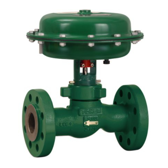
Figure 1. Fisher D3 Control Valve with easy-Drive
1
1
3
3
3
3
4
5
8
9
9
9
. . .
9
9
11
15
14
16
18
20
22
22
22
25
D3 Valve with easy-Drive Actuator
Electric
™
Emerson sales office
October 2017
or
Advertisement
Table of Contents

Related Manuals for Emerson Fisher D3


Summary of Contents for Emerson Fisher D3
-
Page 1: Table Of Contents
Introduction Scope of Manual This instruction manual provides installation, maintenance, and parts information for the Fisher D3 control valve with easy-Drive electric actuator. Do not install, operate, or maintain a D3 valve with easy-Drive electric actuator without being fully trained and qualified in valve, actuator, and accessory installation, operation, and maintenance. -
Page 2: Electric Actuator
Instruction Manual D3 Valve with easy-Drive Actuator October 2017 D103460X012 Table 1. Specifications Valve Body Sizes, End Connection Styles, and Port Available Actuator Configurations Diameters On/off (snap acting) Positioning (flow or pressure control) RAISED FACE VALVE PORT THREADED (RF) FLANGED SIZE, DIAMETER, (INCHES) -
Page 3: Description
Educational Services For information on available courses for the Fisher D3 control valve with easy-Drive electric actuator, as well as a variety of other products, contact:... -
Page 4: Special Instructions For "Safe Use" And Installations In Hazardous Locations
Emerson sales office or Local Business Partner. To avoid product damage, inspect the valve before installation for any damage or any foreign material that may have collected in the valve body. -
Page 5: Startup Overview
Instruction Manual D3 Valve with easy-Drive Actuator D103460X012 October 2017 Startup Overview Figure 2. Flowchart WIRE PER WIRING INSTRUCTIONS ON PAGES 6-8 IS YOUR CONTROL METHOD LISTED IN TABLE 2 ON PAGE 9? PROCEED TO MODBUS SETUP SECTION ON ARE YOU USING MODBUS PAGE 9 TO MONITOR REGISTERS? PROCEED TO... - Page 6 Instruction Manual D3 Valve with easy-Drive Actuator October 2017 D103460X012 Figure 3. Fisher D3 Valve with easy-Drive Actuator Wiring Diagram CONTROLLER FIELD WIRING CONNECTIONS POWER AND CONTROL TERMINAL MOTOR / GEARBOX ASSY (GE48474) GE47302-7 TOP VIEW CONTROLLER Power Requirements Ensure a stable DC power source is available, maintaining less than 5% ripple and sufficiently surge protected for the application.
- Page 7 Instruction Manual D3 Valve with easy-Drive Actuator D103460X012 October 2017 Figure 4. Wiring - Analog Input Analog Input (420mA: 40033=1, 40034=1, 40043=0 1. Connect signal to terminal 3 2. Connect reference to terminal 4 3. Connect 250 ohm resistor between terminals 3 and 4 as shown.
-
Page 8: Important Technical Notice For Easy-Drive Electric Actuator
Instruction Manual D3 Valve with easy-Drive Actuator October 2017 D103460X012 Figure 6. Wiring - Single Dry Contact Dry Contact (single dry contact: 40033=0, 40034=0, 40043=1) 1. Connect one side of contact switch to terminal 1 (COMM) 2. Connect other side of contact switch to terminal 2 (N.O.) Figure 7. -
Page 9: Default Input Signals
All configuration within the valve is done by setting values in Modbus registers. This can be done using any Modbus master (flow computer, PLC, PC). Configuration software, providing a visual interface to the registers, is available through your Emerson sales office or Local Business Partner. Modbus setup Use the instructions in the instruction manual for the Modbus master to initiate the connection. - Page 10 Instruction Manual D3 Valve with easy-Drive Actuator October 2017 D103460X012 When a connection has been achieved, the actuator may be configured to accept the input signal over the Modbus link (ignoring the physical inputs) and the Modbus settings may be changed to accommodate the network to which it is attached.
-
Page 11: Calibration Instructions
Instruction Manual D3 Valve with easy-Drive Actuator D103460X012 October 2017 signal or to the value in Modbus register 40001. A value of 0 in register 40034 will result in the actuator responding to the value in 40001 and a value of 1 will result in the actuator responding to physical control signals. Note If an actuator is on/off, a Modbus command of 049 in register 40001 will cause the valve to close fully, while a value of 50100 will cause the valve to open fully. - Page 12 Instruction Manual D3 Valve with easy-Drive Actuator October 2017 D103460X012 It is not necessary to calibrate your easyDrive electric actuator prior to use from a factory shipment. If any of the following are true, recalibration will be required (see next section) D A change in the FloPro setting D The actuator has been remounted on a different valve since shipment D Disassembly of the valve for trim or packing changes...
- Page 13 Instruction Manual D3 Valve with easy-Drive Actuator D103460X012 October 2017 6. For positioning operation using 420mA: a. Apply a 20mA signal between pins 3 and 4 – valve plug will not move at this time. b. Apply a 4mA signal between pins 3 and 4 – valve plug will move to the upper stop, immediately followed by moving to the lower, closed position.
-
Page 14: Troubleshooting
If register 40025 shows 0 and the circuit board is green (not blue), it is possible a 420mA signal was applied without power to the power terminals and damage to the input circuitry has occurred. Contact your Emerson sales office or Local Business Partner for further information. -
Page 15: Setting The Valve Flow Adjuster
D3 Valve with easy-Drive Actuator D103460X012 October 2017 ii. If positioning control is desired, contact your Emerson sales office or Local Business Partner to upgrade your actuator to positioning control. 4. Diagnostics show a Motor Stall Fault. a. The easyDrive electric actuator is designed to operate in a manner consistent with a pneumatic actuator. This means that if the valve plug can not move to its commanded position, the actuator will stop, without damage, and issue a Motor Stall Fault warning. -
Page 16: Maintenance
Instruction Manual D3 Valve with easy-Drive Actuator October 2017 D103460X012 When shipped from the factory, the actuator has the flow adjuster set at the maximum flow rate position for the given port size. 1. Ensure the valve plug is in the seated position. 2. - Page 17 Instruction Manual D3 Valve with easy-Drive Actuator D103460X012 October 2017 Figure 10. Packing and Belleville Spring Stacking Order FEMALE PACKING ADAPTOR LUBRICATE WITH 3mm (1/8 INCH BEAD) OF SUPPLIED HIGH PERFORMANCE FLUORINATED GREASE (KEY 44) PACKING RING LUBRICATE WITH 3mm (1/8 INCH BEAD) OF SUPPLIED HIGH PERFORMANCE FLUORINATED GREASE...
-
Page 18: Valve Plug And Seat Ring Maintenance
Instruction Manual D3 Valve with easy-Drive Actuator October 2017 D103460X012 Figure 11. Packing and Belleville Spring Stacking Order UNTIGHTENED, FULLY TIGHTENED, NOTE THE GAP NO GAP PACKING RETAINER (KEY 8) VALVE PLUG, BELLEVILLE SPRINGS, AND PACKING RETAINER CORRECTLY BELLEVILLE SPRINGS FULLY ENCLOSED BY INSTALLED AND TIGHTENED THE PACKING RETAINER Valve Plug and Seat Ring Maintenance... - Page 19 Instruction Manual D3 Valve with easy-Drive Actuator D103460X012 October 2017 7. Break the bonnet nut (key 5) loose with a hammer. Continue turning the bonnet nut by using a hammer or a large adjustable wrench, tightened around one ear of the bonnet nut. If the bonnet (key 7) is stuck in the valve, continue to unscrew the bonnet nut.
-
Page 20: Packing Maintenance
Instruction Manual D3 Valve with easy-Drive Actuator October 2017 D103460X012 10. Apply anti‐seize lubricant to the threads on the valve body and bonnet nut (key 5) and the contact surfaces of the bonnet and bonnet nut flange. Install the bonnet and actuator assembly onto the valve body. Tighten the bonnet nut until the nut stops turning. - Page 21 Instruction Manual D3 Valve with easy-Drive Actuator D103460X012 October 2017 6. Install the male packing adaptor, lower anti‐extrusion washer (key 10), and lower packing spacer over the valve stem as shown in figure 10. 7. Firmly press all packing parts into the packing bore with a tube. 8.
-
Page 22: Parts Ordering
Local Business Partner for assistance or when ordering replacement parts. WARNING Use only genuine Fisher replacement parts. Components that are not supplied by Emerson Automation Solutions should not, under any circumstances, be used in any Fisher valve, because they may void your warranty, might adversely affect the performance of the valve, and could cause personal injury and property damage. - Page 23 Instruction Manual D3 Valve with easy-Drive Actuator D103460X012 October 2017 Figure 12. D3 Valve Assembly 13 mm 13 mm 11/16 INCH 1-1/2 INCH...
- Page 24 Instruction Manual D3 Valve with easy-Drive Actuator October 2017 D103460X012 Figure 13. D3 Valve Assembly - Cross Sectional View APPLY LUBRICANT GE49376-B...
-
Page 25: Appendix A - Modbus
Instruction Manual D3 Valve with easy-Drive Actuator D103460X012 October 2017 Appendix A - Modbus A.1 Register Summary Table 4. Register Summary DATA LEGAL FUNCTION CODES REGISTER (PHYSICAL) TYPE DESCRIPTION 03 – Read Holding Reg Position Demand – Proportional 06 – Write Single Reg 40001 (0x0000) UINT16 Value 0-100 = 0-100% Position... - Page 26 Instruction Manual D3 Valve with easy-Drive Actuator October 2017 D103460X012 Table 4. Register Summary (continued) DATA LEGAL FUNCTION CODES REGISTER (PHYSICAL) TYPE DESCRIPTION Reserved 03 – Read Holding Reg 40031 (0x001E) UINT16 Read will return power up default of 0 03 –...
- Page 27 Instruction Manual D3 Valve with easy-Drive Actuator D103460X012 October 2017 Table 5. Fault Register – Fault Flags Summary Table Diagnostic Flags – Bit Diagnostic Flags – Binary Mask Value Description Mask Value 0x8001 1000 0000 0000 0000 Fault in N.V. Memory – system has restored default settings 0x4000 0100 0000 0000 0000 Motor assembly stall...
- Page 28 Instruction Manual D3 Valve with easy-Drive Actuator October 2017 D103460X012 A.2.5 Overspeed Condition The drive speed was detected as being over the speed 3300RPM. This fault latches and needs to be reset. A.2.6 Calibration Span Not in Legal Range Following a calibration the detected mechanical travel was detected as being too short for the valve type. This fault latches and needs to be reset.
- Page 29 Instruction Manual D3 Valve with easy-Drive Actuator D103460X012 October 2017 A.2.15 Analog Input Initialized The analog input has been detected as having a control signal within the expected range of 3-20mA. If the analog input is the selected control signal then this will activate the valve after the startup period. A.2.16 Start Delay Active This is a flag set during the startup phase of operation, if this is set then the valve may be recalibrated by sending the calibration signal sequence (100% demand followed by 0%).
- Page 30 Instruction Manual D3 Valve with easy-Drive Actuator October 2017 D103460X012 0x06 – Write Single register, or 0x03 – Read Holding registers. Description: This is a register is used to initiate a calibration of the analog to digital circuit in the system. A write of a ‘1’...
- Page 31 Instruction Manual D3 Valve with easy-Drive Actuator D103460X012 October 2017 until the cause of the fault condition has been removed and the fault condition reset by writing a reset request to register 40001. The upper order byte contains flags used to indicate the operational status of the valve actuator.
- Page 32 Instruction Manual D3 Valve with easy-Drive Actuator October 2017 D103460X012 Description: This is a pair of registers that hold a 32 bit number that can be used to hold a unique serial number. The register needs to be read using a single read Modbus function transaction command to ensure coherency of the data in the two registers.
- Page 33 Instruction Manual D3 Valve with easy-Drive Actuator D103460X012 October 2017 A.3.23 40032 Valve Type [Read & Write] Register: 40032, Address 0x001F (31). Function code: 0x10 – Write Multiple registers, 0x06 – Write Single register, or 0x03 – Read Holding registers. Description: This is a register that holds an enumeration of the three types of valve.
- Page 34 Instruction Manual D3 Valve with easy-Drive Actuator October 2017 D103460X012 A.3.28 40037 Low travel Cutoff [Read & Write] Register: 40037, Address 0x0024 (36). Function code: 0x10 – Write Multiple registers, 0x06 – Write Single register, or 0x03 – Read Holding registers. Description: This is a register that holds an integer value of percentage used as a clamp –...
- Page 35 Instruction Manual D3 Valve with easy-Drive Actuator D103460X012 October 2017 A.3.33 40042 Reset Statistics [Read & Write] Register: 40042, Address 0x0029 (41). Function code: 0x10 – Write Multiple registers, 0x06 – Write Single register, or 0x03 – Read Holding registers. Description: This is a register used to reset the non volatile system statistics (such as number of hours run).
- Page 36 Fisher and easy-Drive are marks owned by one of the companies in the Emerson Automation Solutions business unit of Emerson Electric Co. Emerson Automation Solutions, Emerson, and the Emerson logo are trademarks and service marks of Emerson Electric Co. All other marks are the property of their respective owners.