Table of Contents
Advertisement
Quick Links
Advertisement
Table of Contents

Related Manuals for ABB AC-AP Series


Summary of Contents for ABB AC-AP Series
- Page 1 — OPTIONS FOR ABB DRIVES ACx-AP-x Assistant control panels User’s manual...
- Page 2 You can find manuals and other product documents in PDF format on the Internet. See section Document library on the Internet on the inside of the back cover. For manuals not available in the Document library, contact your local ABB representative.
- Page 3 User’s manual ACx-AP-x Assistant control panels Table of contents 2018 ABB Oy. All Rights Reserved. 3AUA0000085685 Rev E EFFECTIVE: 2018-07-11...
-
Page 5: Table Of Contents
Table of contents 5 Table of contents 1. Introduction to the manual What this chapter contains ........... . 9 Applicability . - Page 6 6 Table of contents 5. Functions in the main Menu What this chapter contains ........... 33 Menu .
- Page 7 Table of contents 7 Backups ............. . . 55 Customized content .
- Page 8 8 Table of contents Generic disclaimer ............72 Cybersecurity disclaimer .
-
Page 9: Introduction To The Manual
Introduction to the manual 9 Introduction to the manual What this chapter contains The chapter describes the applicability, compatibility, intended audience and the contents of this manual. Applicability This manual applies to the following panel types and their versions: Control panel type ACS-AP-I and ACS-AP-W ACH-AP-H ACH-AP-W... -
Page 10: Compatibility
10 Introduction to the manual Note: The images and instructions in this manual are examples, each based on a specific control panel and drive type combination. The details may vary with different control panels or drive types. Compatibility The following drive(s) are compatible with these panel types. Control ACS-AP-I ACS-AP-S... - Page 11 Introduction to the manual 11 • Technical data describes the parts, dimensions and materials of the control panel, and other technical data about the control panel.
- Page 12 12 Introduction to the manual...
-
Page 13: Installation And Start-Up
Installation and start-up 13 Installation and start-up What this chapter contains The chapter describes how to install and start-up the Assistant control panel for the first time. Installation Attach the control panel directly to the drive or use a separate mounting kit (for example, for cabinet door mounting). -
Page 14: First Start-Up
14 Installation and start-up First start-up To start-up the control panel for the first time, follow the instructions: 1. Obey all drive-specific safety precautions. 2. Install the control panel. See instructions Installation (page 13). 3. Power up the drive. The control panel start-up begins automatically. - Page 15 Installation and start-up 15 Once you are in the Home view, the control panel is ready for use.
- Page 16 16 Installation and start-up...
-
Page 17: Control Panel Overview
Control panel overview 17 Control panel overview What this chapter contains The chapter describes the display, keys and main parts of the Assistant control panel. -
Page 18: Display, Keys And Parts
18 Control panel overview Display, keys and parts Display USB connector Left softkey Clip Right softkey RJ-45 connector Status LED Type code label on the panel Help Battery cover Arrow keys Stop (see Start and Stop) Hand Start (see Start and Stop) Auto Local/Remote (see Loc/Rem) -
Page 19: Display
Control panel overview 19 Display In most views, the following control panel elements are shown on the display: No. Panel element Function Control location Indicates how the drive is controlled: and related icons No text: The drive is in local control, but controlled from another device. -
Page 20: Keys
20 Control panel overview No. Panel element Function Status icon Indicates the status of the drive and the motor. The direction of the arrow indicates forward (clockwise) or reverse (counter-clockwise) active reference direction. Note: For non-rotating driven equipment, the numbers 1 and 0 are used to indicate that the drive is running or stopped, respectively. -
Page 21: Right Softkey
Control panel overview 21 Right softkey The right softkey ( ) is usually used for selecting, accepting and confirming. The function of the right softkey in a given situation is shown by the softkey selection in the bottom right corner of the display. Arrow keys The up and down arrow keys ( ) are used to highlight selections in menus... -
Page 22: Status Led
22 Control panel overview Key shortcuts The table below lists key shortcuts and combinations. Simultaneous key presses are indicated by the plus sign (+). Shortcut Available in... Effect any view Save a screenshot. Up to fifteen images can be stored in the control panel memory. -
Page 23: Connector
The type code label on the panel contains revision information. See an example label below. MRP code Type code Serial number ABB Oy ABB Oy M/N ACS-AP-W S/N:B5320064WU CODE:3AXD50000025964 FCC ID FCC ID: 2AFNGAPWSERIES IC:20555-APWSERIES and IC CANADA code numbers... -
Page 24: Battery Cover
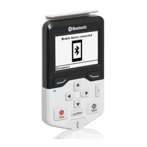
Wireless interface The ACS-AP-W and ACH-AP-W Assistant control panels with Bluetooth interface enable wireless interface for ABB drives. The wireless panels are also embedded with powerful processor and memory that enables faster communication. The functions of • ACS-AP-W panel are same with ACS-AP-I and ACS-AP-S panels, and... -
Page 25: Basic Operation
Basic operation 25 Basic operation What this chapter contains The chapter describes the basic operations and components of the user interface. It also lists the common user tasks and provides instructions to complete the task. User interface overview The user interface has the following main components: Component Description Home view... -
Page 26: Control Panel Navigation
26 Basic operation Control panel navigation Use the arrow keys and softkeys for navigation. Follow the choices on the screen. Home view Options Menu Parameters Reference Assistants Direction change Select drive Energy efficiency Edit Home view Event log Active faults History graphs Active warnings Backups... -
Page 27: Home View
Basic operation 27 Home view The main view of the control panel is called the Home view. In the Home view, you can monitor the status of the drive, such as its speed, torque or power. The Home view has one or more pages, each of which can display up to three signals. The number of pages and the signals shown on each page are customizable, and the Home view configuration is saved to the drive whenever you change it. -
Page 28: Help
28 Basic operation Help You can open a context-sensitive help page in all menus and views by pressing The help page provides information on the use of the current view or menu, or on possible problems associated with it. On the help page, you can press again or press (Exit) to exit. -
Page 29: Common User Tasks
Basic operation 29 Common user tasks The following tables list common user tasks and describes how to complete the task. See chapters Functions in the main Menu (page 33) and Functions in the Options menu (page 49) for detailed descriptions of functions in the menus. Note: The Menu options varies based on the drive/device to which the control panel is connected. -
Page 30: System Information And Help
30 Basic operation System information and help Task Actions How to get help. Press to open the context-sensitive help. → → To view drive information. Go to Menu System info Drive. → → To view control panel version. Go to Menu System info Control panel. -
Page 31: Backups
Basic operation 31 Backups Task Actions Create a backup. Creating a parameter backup (page 42). Restore a backup. Restoring a parameter backup (page 42). - Page 32 32 Basic operation...
-
Page 33: Functions In The Main Menu
Functions in the main Menu 33 Functions in the main Menu What this chapter contains The chapter describes the functions in the main Menu. Menu All functions of the control panel are accessed through the Menu which is the main menu of the user interface. -
Page 34: Navigating In The Menu
34 Functions in the main Menu Sub-menu Function See page... Primary settings View and change settings related to motor, PID, fieldbus, advanced functions, clock, region, and display. Provides terminal name, number, electrical status and logical meaning of the drive. Diagnostics Provides faults and warnings information and helps to resolve potential problems. -
Page 35: Favorites
Functions in the main Menu 35 Favorites In the Favorites sub-menu, only user-selected parameters are listed. The order is determined by the parameter number. Editing the list of favorites 1. Select Edit. 2. Check parameters you want to show on the list by pressing (Select). -
Page 36: Editing Numeric Parameters
36 Functions in the main Menu 5. Press to restore the default value of the parameter (this does not save it). See the sections below for more information on editing specific parameter types. Editing numeric parameters Numeric parameters include parameters with linear numeric values, passcodes, time and date parameters, durations and exception dates. -
Page 37: Parameters
Functions in the main Menu 37 To select a parameter, follow the instructions: 1. Select Other to move to a list of parameter groups. 2. Select a parameter group to move to a list of parameters. 3. Depending on the parameter you are editing, you must select a parameter or an individual bit, or you may choose either of the two. -
Page 38: Editing Bit-Field Parameters
38 Functions in the main Menu Editing bit-field parameters A bit-field parameter is a bit word whose individual bits can be edited. The labels describe the function of each bit, and the current state of the bit is shown as 1 or 0. -
Page 39: Assistants
You can also generate a QR code, which is an optical code containing information of the drive. The code can be read with ABB application and mobile device. -
Page 40: Energy Efficiency
40 Functions in the main Menu The control panel collects data and generates the code. Press << or >> to navigate to the next screen. → → You can also generate QR code from Menu System info QR code. See System info (page 43). -
Page 41: History Graphs
Functions in the main Menu 41 History graphs The History graphs menu contains Trends and Load profile sub-menu. Trends This functionality is available in a future release. Load profile In the Load profile submenu, you can view and configure load profiles. -
Page 42: Creating A Parameter Backup
42 Functions in the main Menu Some of the Backup icons are listed below: Creating a parameter backup 1. In the Backups menu, select Create backup. If there is a free backup slot in the control panel, the following step is skipped. 2. -
Page 43: System Info
Functions in the main Menu 43 • To select production data items, select Select prod. data items and select the desired production data and then select restore. 4. Wait until the restore is completed. An animation is shown on the control panel during the restoring process.The control panel automatically returns to the Backups menu. -
Page 44: Settings
Sub-menu Function QR code Shows an optical code containing information of the drive. The code can be read with ABB application and mobile device. To generate the QR code, press (Continue). The control panel collects data and creates the code. -
Page 45: Primary Settings
Functions in the main Menu 45 Sub-menu Function Show in lists Show or hide the numeric IDs of: • parameters and groups • option list items • bits → • devices in Options Select drive. Pass code Enter pass codes into this parameter to activate further access levels (for example additional parameters). -
Page 46: I/O
46 Functions in the main Menu Sub-menu Function Set up the settings and actual values for the process PID controller. PID is only used in remote control. Fieldbus To make the protocol configurations easier. Advanced options/ Contains settings for advanced functions, such as triggering or resetting functions faults through I/O, or switching between entire set of settings. - Page 47 Functions in the main Menu 47 Sub-menu Function Fieldbus Provides status information and sent and received data from fieldbus for troubleshooting. Load profile Provides status information of load distribution (that is, drive running time spent on each load level) and peak load levels.
- Page 48 48 Functions in the main Menu...
-
Page 49: Functions In The Options Menu
Functions in the Options menu 49 Functions in the Options menu What this chapter contains The chapter describes functions in the Options menu. Options menu In the Options menu, you can control the settings related to the Home view. Note: The contents displayed may vary based on the drive/device to which the panel is connected. -
Page 50: Setting The Reference
50 Functions in the Options menu Setting the reference You can change the reference when the drive is in the local control mode. You can also change the reference in remote control mode if the drive configuration permits it. Changes take effect when saved with a key press. to switch to the local control mode, if the text in the top left 1. - Page 51 Functions in the Options menu 51 4. Use to move the cursor highlight. • To add a new parameter to an existing page, highlight an area above, between or below an existing parameter. • To edit or remove an existing parameter, highlight that parameter.
- Page 52 52 Functions in the Options menu Note: The data shown in the graph is not stored in the drive memory, that is, if you remove or restart the control panel, the data is lost. • Display decimals: Specifies how many decimals are shown. •...
-
Page 53: Control Of Multiple Drives
Control of multiple drives 53 Control of multiple drives What this chapter contains The chapter describes how to control several drives with one control panel. Connecting multiple drives to a control panel 1. Connect the control panel (A) to the first drive (B) in the panel bus. 2. -
Page 54: Selecting Drive Menu
54 Control of multiple drives Selecting drive menu In the Options menu, select Select drive which lists all the drives connected to the panel bus and shows their current status. If panel bus is not enabled, only one drive is shown. -
Page 55: Graph Data
Control of multiple drives 55 Graph data The data for the graph format in the Home view is stored in the control panel only for the selected drive. Upon changing the selected drive, any stored graph data is discarded, and graph data collection begins for the new drive. History graphs and all related settings (signal selection, horizontal timescale) are saved in the drive, and the History graphs menu shows always the graphs for the currently selected drive. - Page 56 56 Control of multiple drives...
-
Page 57: Fault Tracing
Fault tracing 57 Fault tracing What this chapter contains This chapter describes how to identify different fault and warning messages that are shown on the control panel and how to solve problem situations. Identifying error and warning messages Faults and warnings are drive states that occur when the drive detects a problem in its operation. - Page 58 58 Fault tracing Refer to the table below to identify faults and warnings. Display Type continuous red Faults (page 59). blinking red Faults of this type require stopping and restarting the drive before it continues to function normally. Faults (page 59). continuous red A fault has occurred in another drive in the panel bus.
-
Page 59: Faults
Fault tracing 59 Faults Faults are problems that require your attention before you start the drive again. Refer the following steps to solve the fault situation: 1. Identify and eliminate the cause of the fault. In the Fault view, you can see the fault code. - Page 60 60 Fault tracing...
-
Page 61: Service And Maintenance
Service and maintenance 61 Service and maintenance What this chapter contains This chapter describes the service and maintenance tasks of the Assistant control panel. Removing the control panel cover It is possible to remove the control panel cover to clean any dust inside the cover or to change the cover to customize the control panel. -
Page 62: Cleaning The Connectors
6. Dispose of the old battery according to local disposal rules or applicable laws. Control panel software updates If the control panel software needs to be updated, contact ABB. Recycling instructions and environmental information See the drive related Recycling instructions and environmental information. -
Page 63: Panel-To-Pc Usb Connection
Panel-to-PC USB connection 63 Panel-to-PC USB connection What this chapter contains This chapter describes the USB connection between the Assistant control panel and a PC. USB connection The three main functions of the USB connection are: • The control panel acts as an USB adapter, allowing the PC tool to interact with the drive. -
Page 64: Connecting Control Panel To Pc Usb
64 Panel-to-PC USB connection Connecting control panel to PC USB Note: When connected to a PC, the control panel displays the USB screen and does not respond to key presses. In this mode, you can only interact with the control panel or the drive through the PC tool. -
Page 65: Connecting A Pc Tool To A Drive Through The Control Panel
Connecting a PC tool to a drive through the control panel You can use the control panel to connect an ABB PC tool to the drive. When using the control panel, you can only access the drive from the PC tool. -
Page 66: Transferring Files Between The Control Panel And A Pc
2. If Windows prompts you to install USB drivers, install them as instructed in Drive composer user’s manual (3AUA0000094606 [English]). The control panel appears as an MTP device in Windows Explorer. 3. Open ABB Drives Assistant control panel with Windows Explorer, and go to the directory where the files are stored. •... -
Page 67: Technical Data
Technical data 67 Technical data What this chapter contains This chapter contains the technical details of the Assistant control panel. Connectors The control panel has the following connectors: Connector Purpose RJ-45 female Used for connecting the panel to drive. connector •... -
Page 68: Battery
68 Technical data Battery At an ambient temperature of 25 °C (77 °F), the change interval of the real-time clock battery is approximately 10 years. Battery type CR2032 DMS documents: 3AXD00000587751, 3AXD10000371905 Dimensions and weight Weight 130 g Height, width and depth mm [in.] Degrees of protection Degree of protection, attached to a drive... -
Page 69: Materials
Technical data 69 Materials Enclosure PC/ABS Packaging Cardboard Screen Polycarbonate Disposal Do not dispose the control panel with municipal waste. Check the local regulations for disposal of electronic products. See also, drive related Recycling instructions and environmental information. Environmental limits Operation Storage Transportation... -
Page 70: Lcd Specifications
70 Technical data LCD specifications LCD type FSTN, negative transmissive Operating temperature -20 °C to +70 °C (-4 °F to 158 °F) Storage temperature -40 °C to +80 °C (-40 °F to 176 °F) Transportation temperature -40 °C to +80 °C (-40 °F to 176 °F) Driver IC UC1698U ROHS... -
Page 71: Fcc And Industry Canada Certifications
• Modifications not expressly approved by ABB Oy could void the user's authority to operate the wireless panels. -
Page 72: Disclaimers
ABB and its affiliates are not liable for damages and/or losses related to such security breaches, any unauthorized access,... - Page 73 —...
- Page 74 © Copyright 2018 ABB. All rights reserved. Specifications subject to change without notice.