Advertisement
Table of Contents
- 1 Table of Contents
- 2 Warning Decal Placement
- 3 Important Precautions
- 4 Before You Begin
- 5 Part Identification Chart
- 6 Assembly
- 7 How to Use the Trainer
- 8 Maintenance and Troubleshooting
- 9 Exercise Guidelines
- 10 Part List
- 11 Exploded Drawing
- 12 Ordering Replacement Parts
- 13 Recycling Information
- Download this manual
Model No. PFEVEL71216.0
Serial No.
Write the serial number in the space
above for reference.
CUSTOMER SERVICE
UNITED KINGDOM
Call: 0330 123 1045
From Ireland: 053 92 36102
Website: www.iconsupport.eu
E-mail: csuk@iconeurope.com
Write:
ICON Health & Fitness, Ltd.
Unit 1D, The Gateway
Fryers Way, Silkwood Park
OSSETT
WF5 9TJ
UNITED KINGDOM
AUSTRALIA
Call: 1800 993 770
E-mail: australiacc@iconfitness.com
Write:
ICON Health & Fitness
PO Box 635
WINSTON HILLS NSW 2153
AUSTRALIA
CAUTION
Read all precautions and
instructions in this manual before
using this equipment. Keep this
manual for future reference.
Serial
Number
Decal
USER'S MANUAL
www.iconeurope.com
Advertisement
Table of Contents

Related Manuals for Pro-Form PFEVEL71216.0


Summary of Contents for Pro-Form PFEVEL71216.0
- Page 1 Model No. PFEVEL71216.0 Serial No. USER’S MANUAL Write the serial number in the space above for reference. Serial Number Decal CUSTOMER SERVICE UNITED KINGDOM Call: 0330 123 1045 From Ireland: 053 92 36102 Website: www.iconsupport.eu E-mail: csuk@iconeurope.com Write: ICON Health & Fitness, Ltd.
-
Page 2: Table Of Contents
TABLE OF CONTENTS WARNING DECAL PLACEMENT ............. . .2 IMPORTANT PRECAUTIONS . -
Page 3: Important Precautions
IMPORTANT PRECAUTIONS WARNING: To reduce the risk of serious injury, read all important precautions and instructions in this manual and all warnings on the trainer before using the trainer. ICON assumes no responsibility for personal injury or property damage sustained by or through the use of this product. -
Page 4: Before You Begin
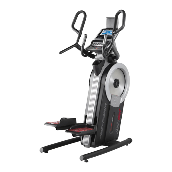
BEFORE YOU BEGIN Thank you for selecting the revolutionary PROFORM reading this manual, please see the front cover of this ® CARDIO HIIT TRAINER. The CARDIO HIIT TRAINER manual. To help us assist you, note the product model trainer provides an impressive selection of features number and serial number before contacting us. -
Page 5: Part Identification Chart
PART IDENTIFICATION CHART Use the drawings below to identify the small parts needed for assembly. The number in parentheses below each drawing is the key number of the part, from the PART LIST near the end of this manual. The number following the key number is the quantity needed for assembly. -
Page 6: Assembly
ASSEMBLY • Assembly requires two persons. • In addition to the included tool(s), assembly requires the following tools: • Place all parts in a cleared area and remove the one Phillips screwdriver packing materials. Do not dispose of the packing materials until you finish all assembly steps. - Page 7 2. With the help of a second person, place some of the packing materials (not shown) under the right side of the Frame (1). Have the second person hold the Frame to prevent it from tipping while you complete this step. Identify the Right and Left Stabilizers (8, 9) and orient them as shown.
- Page 8 4. Attach the Right Pedal Base (2) to the Right Pedal Leg (24) with four M8 x 20mm Screws (102); start all the Screws, and then tighten them. Attach the Left Pedal Base (not shown) to the Left Pedal Leg (not shown) in the same way. 5.
- Page 9 6. See the upper drawing. With the help of a second person, orient the Console (5), the Console Cover (7), and the Console Bracket (4) as shown. Route the wires (A) on the Console through the Console Cover and the Console Bracket as shown;...
- Page 10 8. While a second person holds the Console Bracket (4) near the Frame (1), connect the wires on the Console to the Main Wire (115) and to the Pulse Wire (117). Avoid pinching the wires Tip: Avoid pinching the wires. Attach the Console Bracket (4) to the Frame (1) with two M8 x 86mm Screws (109) and two M8 x 15mm Screws (96);...
- Page 11 10. Identify the Rear and Front Pivot Covers (65, 66). Press a set of Rear and Front Pivot Covers (65, 66) together around the Right Handlebar (10) near the bend (A). Then, attach them to each other with two M4 x 22mm Screws (107). See the inset drawing.
- Page 12 12. Plug the Power Adapter (118) into the receptacle on the frame of the trainer. Note: To plug the Power Adapter (118) into an outlet, see HOW TO PLUG IN THE POWER ADAPTER on page 13. 13. Make sure that all parts are properly tightened before you use the trainer. Extra parts may be included. Place a mat beneath the trainer to protect the floor.
-
Page 13: How To Use The Trainer
HOW TO USE THE TRAINER HOW TO PLUG IN THE POWER ADAPTER HOW TO MOVE THE TRAINER IMPORTANT: If the trainer has been exposed to Due to the size and weight of the trainer, moving cold temperatures, allow it to warm to room tem- it requires two persons. - Page 14 HOW TO EXERCISE ON THE TRAINER HOW TO LEVEL THE TRAINER To mount the trainer, hold the handlebars or the pulse If the trainer grips and step onto the pedal that is in the lower posi- rocks slightly tion. Then, step onto the other pedal. Push the pedals on your floor until they begin to move with a continuous motion.
- Page 15 CONSOLE DIAGRAM FEATURES OF THE CONSOLE The advanced console offers an array of features designed to make your workouts more effective and enjoyable. When you use the manual mode, you can change the resistance of the pedals with the touch of a button. As you exercise, the console will provide continu- ous exercise feedback.
- Page 16 HOW TO USE THE MANUAL MODE Calories (Cals.)—When the manual mode is selected, this display mode will show the approxi- 1. Turn on the console. mate number of calories you have burned. When a workout is selected, this display mode will show Begin pedaling or press any button on the console either the approximate number of calories remain- to turn on the console.
- Page 17 My Trail—This tab will show a track that represents 5. Measure your heart rate if desired. 1/4 mile (400 m). As you exercise, the flashing rectangle will show your progress. The My Trail tab You can measure your heart rate using either will also show the number of laps you complete.
- Page 18 6. Turn on the fan if desired. 3. Start the workout. The fan has several speed set- Press the Begin button or begin pedaling to start tings. Press the fan increase the workout. and decrease buttons repeat- edly to select a fan speed or to Each workout is divided into segments.
- Page 19 IMPORTANT: The target speed is intended only HOW TO USE THE SOUND SYSTEM to provide motivation. Your actual pedaling speed may be slower than the target speed. To play music or audio books through the console Make sure to pedal at a speed that is comfort- sound system while you exercise, plug a 3.5 mm male able for you.
- Page 20 HOW TO CONNECT YOUR SMART DEVICE TO THE 4. Disconnect your smart device from the console CONSOLE if desired. The console supports BLUETOOTH connections to To disconnect your smart device from the console, smart devices via the iFit app and to compatible heart press and hold the Bluetooth Smart button on the rate monitors.
- Page 21 HOW TO CHANGE CONSOLE SETTINGS 3. Change settings as desired. 1. Select the settings mode. Units—The currently selected unit of measurement will appear in the display. To change the unit of To select the settings mode, press the gear button. measurement, press the Enter button repeatedly.
-
Page 22: Maintenance And Troubleshooting
MAINTENANCE AND TROUBLESHOOTING MAINTENANCE Next, remove the four indicated Regular maintenance is important for optimal M4 x 16mm Flat performance and to reduce wear. Inspect and properly Head Screws tighten all parts each time the trainer is used. Replace (101) and the any worn parts immediately. - Page 23 HOW TO ADJUST THE DRIVE BELT Then, locate the lower Adjustment If the pedals slip while you are pedaling, even while Screw (A). the resistance is adjusted to the highest level, the drive Tighten the lower belts may need to be adjusted. To adjust the drive Adjustment Screw belts, first unplug the power adapter.
-
Page 24: Exercise Guidelines
EXERCISE GUIDELINES Burning Fat—To burn fat effectively, you must exer- WARNING: cise at a low intensity level for a sustained period of Before beginning this time. During the first few minutes of exercise, your or any exercise program, consult your physi- body uses carbohydrate calories for energy. - Page 25 SUGGESTED STRETCHES The correct form for several basic stretches is shown at the right. Move slowly as you stretch; never bounce. 1. Toe Touch Stretch Stand with your knees bent slightly and slowly bend forward from your hips. Allow your back and shoulders to relax as you reach down toward your toes as far as possible.
- Page 26 NOTES...
- Page 27 NOTES...
-
Page 28: Part List
PART LIST Model No. PFEVEL71216.0 R0316A Key No. Qty. Description Key No. Qty. Description Frame Right Shield Right Pedal Base Front Cover Left Pedal Base Rear Cover Console Bracket Accessory Tray Base Console Stabilizer Cap Tablet Holder Foot Console Cover... - Page 29 Key No. Qty. Description Key No. Qty. Description M4 x 16mm Flat Head Screw M4 x 12mm Screw M8 x 20mm Screw Main Wire Cap Screw Reed Switch/Wire M6 x 110mm Screw Pulse Wire M8 x 25mm Screw Power Adapter M4 x 16mm Screw Crank Cover Disc M4 x 22mm Screw...
-
Page 30: Exploded Drawing
EXPLODED DRAWING A Model No. PFEVEL71216.0 R0316A... - Page 31 EXPLODED DRAWING B Model No. PFEVEL71216.0 R0316A...
-
Page 32: Ordering Replacement Parts
ORDERING REPLACEMENT PARTS To order replacement parts, please see the front cover of this manual. To help us assist you, be prepared to provide the following information when contacting us: • the model number and serial number of the product (see the front cover of this manual) •...