Table of Contents
Advertisement
Quick Links
Advertisement
Table of Contents

Related Manuals for Swann AMU Powercon

Summary of Contents for Swann AMU Powercon
- Page 1 AMU Powercon Version 6.20 and higher A-96.250.331 / 230320...
- Page 2 For any technical question, contact your nearest SWAN representative, or the manufacturer: SWAN ANALYTISCHE INSTRUMENTE AG Studbachstrasse 13 8340 Hinwil Switzerland Internet: www.swan.ch E-mail: support@swan.ch Document Status AMU Powercon Operator’s Manual Title: A-96.250.331 Revision Issue Sept. 2006 First Edition March 2013 Update to FW release 5.30 July 2019 Update to FW release 6.20...
-
Page 3: Table Of Contents
Single Components ......1.2.1 AMU Powercon Transmitter ..... 1.2.2 Swansensor UP-Con1000 . - Page 4 AMU Powercon Maintenance ........5.1. Maintenance Schedule......
- Page 5 AMU Powercon Safety Instructions AMU Powercon–Operator’s Manual This document describes the main steps for instrument setup, oper- ation and maintenance. Safety Instructions General The instructions included in this section explain the potential risks associated with instrument operation and provide important safety practices designed to minimize these risks.
- Page 6 AMU Powercon Safety Instructions 1.1. Warning Notices The symbols used for safety-related notices have the following sig- nificance: DANGER Your life or physical wellbeing are in serious danger if such warnings are ignored. Follow the prevention instructions carefully. WARNING Severe injuries or damage to the equipment can occur if such warnings are ignored.
- Page 7 AMU Powercon Safety Instructions Warning Signs The importance of the warning signs in this manual. Electrical shock hazard Corrosive Harmful to health Flammable Warning general Attention general 1.2. General Safety Regulations Legal The user is responsible for proper system operation. All precau- tions must be followed to ensure safe operation of the instrument.
- Page 8 AMU Powercon Safety Instructions bility for any claim resulting from unauthorized modification or alter- ation. WARNING Electrical Shock Hazard If proper operation is no longer possible, the instrument must be disconnected from all power lines, and measures must be taken to prevent inadvertent operation.
-
Page 9: Product Description
This instrument is applicable for the measurement of conductivity in high purity water applications. The AMU Powercon measures the specific (total) conductivity or the acid (cation) conductivity of a sample. For the measurement of the acid conductivity a cation exchanger bottle is necessary. The transmitter can be used with a two-electrode conductivity sensor with an integrated Pt1000 temperature sensor, e.g. - Page 10 AMU Powercon Product Description Alarm Relay One potential free contact. Summary alarm indication for program- mable alarm values and Instrument faults. Available in two configurations: Normally open*: Closed during normal operation, open in case of error or power loss.
- Page 11 AMU Powercon Product Description Temperature The mobility of ions in water increases with higher temperature, which enlarges the conductivity. Therefore, the temperature is mea- compensation sured simultaneously by an integrated Pt1000 temperature sensor and the conductivity is compensated to 25 °C. Several temperature compensation curves, designed for different water compositions, can be chosen.
-
Page 12: Single Components
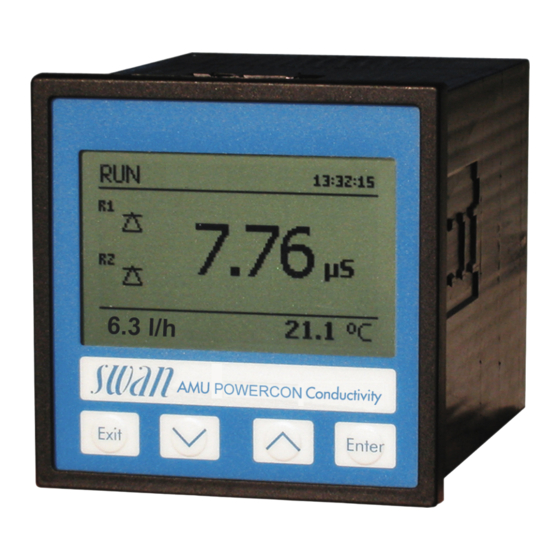
AMU Powercon Product Description 1.2. Single Components 1.2.1 AMU Powercon Transmitter ® General Electronics housing: Noryl resin Protection degree: IP54 (front) Ambient temperature: -10 to +50 °C Humidity: 10–90% rel., non condensing Display: backlit LCD, 75 x 45 mm Dimensions:... - Page 13 AMU Powercon Product Description Measuring Range Resolution range 0.005–0.999 µS/cm 0.001 µS/cm 1.00–9.99 µS/cm 0.01 µS/cm 10.0–99.9 µS/cm 0.1 µS/cm 100–999 µS/cm 1 µS/cm 1.00–2.99 mS/cm 0.01 mS/cm 3.0–9.9 mS/cm 0.1 mS/cm 10–30 mS/cm 1 mS/cm Automatic range switching. Values for a cell constant of 0.0415 cm...
-
Page 14: Swansensor Up-Con1000
AMU Powercon Product Description 1.2.2 Swansensor UP-Con1000 The Swansensor UP-Con1000 is a 2-electrode conductivity sensor for the continuous measurement of specific and acid conductivity with a built-in temperature sensor. Ø 30 Ø 12.7 Ø 24 ” NPT Specifications Measuring range: 0.055–1000 μS/cm... -
Page 15: Flow Cells
AMU Powercon Product Description 1.2.3 Flow Cells The following flow cells can be used: For a slot-lock sensor: B-Flow UP-Con-SL. Q-Flow UP-Con-SL with integrated flow sensor. QV-Flow UP-Con-SL with integrated flow sensor and flow regulating valve. Catconplus-SL with a built-in cation exchanger and flow regu- lating valve. -
Page 16: Installation
AMU Powercon Installation Installation 2.1. Installation Checklist Check Instrument’s specification must conform to your AC power ratings. Do not turn on power until instructed to do so. Installation The transmitter is intended for panel mounting. The dimensions are shown under Dimensions of the AMU Transmitter, p. -
Page 17: Dimensions Of The Amu Transmitter
AMU Powercon Installation 2.2. Dimensions of the AMU Transmitter A-96.250.331 / 230320... -
Page 18: Install The Flow Cell
AMU Powercon Installation 2.3. Install the Flow Cell Example 1 B-Flow UP-CON-SL 161 85 Technical Data Flow cell made of stainless steel SS316L. Insert for sensor with patented SWAN slotlock adapter for quick sensor release. Operating temperature: up to +130 °C ... - Page 19 The Flow cell Catcon+ SL is used for the measurement of the acid (cation) conductivity. Only one sensor can be used together with the AMU Powercon. Therefore the left hand bore has to be closed with a blind plug. Sample ...
-
Page 20: Connecting Sample Inlet And Outlet
AMU Powercon Installation 2.4. Connecting Sample Inlet and Outlet 2.4.1 Swagelok Fitting Stainless Steel at Sample Inlet Preparation Cut the tube to length and deburr it. The tube must be straight and free from blemishes for approximately 1,5 x tube diameter from the end. -
Page 21: Fep Tube At Sample Outlet
AMU Powercon Installation 2.4.2 FEP Tube at Sample Outlet FEP flexible tube 6 mm Ellbow union Compression ferrule Knurled nut Flexible tube Connect the tube to the Serto elbow union and Insert it into an at- mospheric drain of sufficient capacity. -
Page 22: Installation Of Cation Exchanger
AMU Powercon Installation 2.6. Installation of Cation Exchanger Cation ex- The bottle containing the cation exchanger is delivered, but not in- stalled into the flow cell. For transport, an empty bottle has been changer bottle installed into the flow cell. -
Page 23: Electrical Connections
AMU Powercon Installation 2.7. Electrical Connections CAUTION Use only the terminals shown in this diagram, and only for the mentioned purpose. Use of any other terminals will cause short circuits with possible corresponding consequences to material and personnel. A-96.250.331 / 230320... - Page 24 AMU Powercon Installation Rear view of AMU Transmitter (+) (-) 2 3 4 5 6 7 8 9 10 11 12 13 14 RS232 RON OFF A/PB B/PB A-96.250.331 / 230320...
-
Page 25: Power Supply
60245; flammability rating FV1 Mains equipped with an external switch or circuit-breaker – near the instrument – easily accessible to the operator – marked as interrupter for AMU Powercon 2.9. Sensor Connect the sensor to the AMU transmitter according to the con- nection diagram, see Electrical Connections, p. -
Page 26: Relay Contacts
AMU Powercon Installation 2.12. Relay Contacts 2.12.1 Alarm Relay NOTICE: Max. load 100 mA/50 V Alarm output for system errors. Error codes see Error List, p. Terminals Description Active (opened) during normal operation. Normally Closed Inactive (closed) on error and loss of power. -
Page 27: Interfaces
AMU Powercon Installation 2.14. Interfaces 2.14.1 RS232 Interface The RS232 interface is located on the back of the AMU transmitter. The RS232 interface is used for logger download and firmware up- load. 2.14.2 Profibus (optional) To connect several instruments by means of a network or to config- ure a PROFIBUS DP connection, consult the PROFIBUS manual. -
Page 28: Modbus (Optional)
AMU Powercon Installation 2.14.3 Modbus (optional) To connect several instruments by means of a network consult the MODBUS manual. Use appropriate network cable. NOTICE: The switch must be ON if only one instrument is installed, or on the last instrument in the bus... -
Page 29: Instrument Setup
AMU Powercon Instrument Setup Instrument Setup 3.1. Establish sample flow 1 Open flow regulating valve. 2 Wait until the flow cell has been completely filled. 3 Switch on power. 4 Adjust sample flow. 5 Let the instrument run-in for 1 h. - Page 30 AMU Powercon Instrument Setup Measuring unit Menu 5.1.1.2 Set the <Measuring unit> according to your requirements: S/cm S/m External Program all parameters for external devices (interface, recorders, etc.) See program list and explanations 5.2 Signal Outputs, p. 48 devices 4.2 Relay Contacts, p.
-
Page 31: Operation
AMU Powercon Operation Operation 4.1. Keys Exit Enter to exit a menu or command (rejecting any changes) to move back to the previous menu level to move DOWN in a menu list and to decrease digits to move UP in a menu list and to increase digits... -
Page 32: Display
AMU Powercon Operation 4.2. Display 15:20:18 0.178 µS 9.5 l/h 21.8°C normal operation HOLD input closed or cal delay: Instrument on hold (shows status of signal outputs). input closed: control/limit is interrupted (shows status of signal outputs). ERROR Error Fatal Error... -
Page 33: Software Structure
AMU Powercon Operation 4.3. Software Structure Main Menu Messages Diagnostics Maintenance Operation Installation Menu Messages 1 Messages Reveals pending errors as well as an event history Pending Errors (time and state of events that have occurred at an Message List earlier point of time). -
Page 34: Changing Parameters And Values
AMU Powercon Operation 4.4. Changing Parameters and values Changing The following example shows how to set the Q-Flow sensor: parameters 1 Select the parameter you want to Sensors 5.1.1 change. Flow None 2 Press <Enter> Sensor parameters Temp. Compensation Quality Assurance... -
Page 35: Maintenance
AMU Powercon Maintenance Maintenance WARNING Stop operation before maintenance. Stop sample flow. Shut off power of the instrument. 5.1. Maintenance Schedule Preventive maintenance frequency depends on water quality, on the application, and on national regulations. Check sample flow. -
Page 36: Maintenance Of The Sensor
AMU Powercon Maintenance 5.3. Maintenance of the Sensor Blind plug Locking pin locked Locking screw closed Flow cell Alignment marks Conductivity sensor Locking pin unlocked Locking screw open 5.3.1 Remove the Sensor from the Flow Cell To remove the sensor from the flow cell proceed as follows: 1 Press the locking pin [G] down. -
Page 37: Changing The Ion Exchanger
AMU Powercon Maintenance 5.4. Changing the Ion Exchanger The resin of the ion exchanger changes its color from dark violet to brown if the capacity is exhausted. The resin should be changed before no violet resin is left or the cation conductivity rises above the normal value. - Page 38 AMU Powercon Maintenance 8 Pre-rinse the new cation exchanger resin until the display shows stable measuring values. Operation time 1 liter Swan resin This graphic shows the average exhaust time (flow 6 l/h) and must be verified by the user.
-
Page 39: Changing The Inlet Filter
AMU Powercon Maintenance 5.5. Changing the inlet filter The inlet filter of the cation exchanger prevents the resin from en- tering the flow cell. It is located in the inlet filter holder [B]. Bottle holder Inlet filter holder Allen screws Inlet filter 1 Stop sample flow. -
Page 40: Calibration
AMU Powercon Maintenance 5.6. Calibration If you use a UP-Con1000 sensor it is not necessary to calibrate the instrument. A zero measurement is automatically performed every day at 00:30 AM. A calibration is necessary if the cell constant of a sensor is not known. -
Page 41: Longer Stop Of Operation
AMU Powercon Maintenance NOTICE: The temperature algorithm of the 1.413 mS/cm at 25 °C calibration solution is stored in the AMU Powercon transmitter. Provided that the calibration solution has a temperature between 5 °C and 50 °C, and the built-in... -
Page 42: Error List
AMU Powercon Error List Error List Error Non-fatal Error. Indicates an alarm if a programmed value is ex- ceeded. Such Errors are marked E0xx (bold and black). Fatal Error (blinking symbol) Control of dosing devices is interrupted. The indicated measured values are possibly incorrect. - Page 43 AMU Powercon Error List Error Description Corrective action – check process E001 Cond. Alarm high – check programmed value, see 5.3.1.1, p. 53 – check process E002 Cond. Alarm low – check programmed value, see 5.3.1.1, p. 53 – check process E007 Sample Temp.
- Page 44 AMU Powercon Error List Error Description Corrective action – See If Fault Yes is programmed in E024 Input active Menu see 5.3.4, p. 57 – call service E026 IC LM75 – call service E030 EEProm Frontend – call service E031 Cal.
-
Page 45: Program Overview
AMU Powercon Program Overview Program Overview For explanations about each parameter of the menus see Program List and Explanations, p. Menu 1 Messages informs about pending errors and mainte- nance tasks and shows the error history. Password protection possible. No settings can be modified. -
Page 46: Diagnostics (Main Menu 2)
AMU Powercon Program Overview 7.2. Diagnostics (Main Menu 2) Identification Designation AMU Powercon * Menu numbers 2.1* Version V6.20-07/16 Factory Test 2.1.3.1* Instrument 2.1.3* Motherboard Front End Operating Time 2.1.4.1* Years / Days / Hours / Minutes / Seconds 2.1.4* Sensors Cond. -
Page 47: Maintenance (Main Menu 3)
AMU Powercon Program Overview 7.3. Maintenance (Main Menu 3) Calibration 3.1.5* *Menu numbers Follow instructions 3.1* Simulation 3.3.1* Alarm Relay 3.2* Relay 1 3.3.2* 3.3.3* Relay 2 3.3.4* Signal Output 1 3.3.5* Signal Output 2 Set Time (Date), (Time) 3.4* 7.4. -
Page 48: Installation (Main Menu 5)
AMU Powercon Program Overview 7.5. Installation (Main Menu 5) Sensors Flow *Menu numbers None 5.1* 5.1.1* Q-Flow Sensor parameters 5.1.2.1* Cell Constant 5.1.2* Temp. Corr. 5.1.2.2* 5.1.2.3* Cable length 5.1.2.4 Meas. unit Temp.Compensation Comp. none 5.1.3* 5.1.3.1* Coefficient Neutral salts... -
Page 49: Parameter
AMU Powercon Program Overview Relay 1/2 Function 5.3.2.1/ 5.3.3.1* * Menu numbers 5.3.2 /5.3.3* 5.3.2.20/ 5.3.3.20* Parameter 5.3.2.300 / 5.3.3.301* Setpoint 5.3.2.400/ 5.3.3.401* Hysteresis 5.3.2.50/ 5.3.3.50* Delay Input Active 5.3.4.1* 5.3.4* 5.3.4.2* Signal Outputs 5.3.4.3* Output/Control 5.3.4.4* Fault 5.3.4.5* Delay... -
Page 50: Program List And Explanations
AMU Powercon Program List and Explanations Program List and Explanations 1 Messages 1.1 Pending Errors 1.1.5 Provides the list of active errors with their status (active, acknowl- edged). If an active error is acknowledged, the alarm relay is active again. Cleared errors are moved to the Message list. -
Page 51: Maintenance
AMU Powercon Program List and Explanations 2.2.2 Miscellaneous: 2.2.2.1 Case Temp: Shows the current temperature in [°C] inside the trans- mitter. 2.3 Sample 2.3.1 Sample ID: Shows the identification assigned to a sample. This identification is defined by the user to identify the location of the sample. -
Page 52: Operation
AMU Powercon Program List and Explanations The value is simulated by the relay /signal output. Alarm Relay: Active or inactive. Relay 1 and 2: Active or inactive. Signal Output 1 and 2: Actual current in mA At the absence of any key activities, the instrument will switch back to normal mode after 20 min. -
Page 53: Installation
AMU Powercon Program List and Explanations 4.3.1 Log Interval: Select a convenient log interval. Consult the table be- low to estimate the max logging time. When the logging buffer is full, the oldest data record is erased to make room for the newest one (circular buffer). -
Page 54: Signal Output
AMU Powercon Program List and Explanations 5.1.3 Temp. comp: 5.1.3.1 Comp.: Available compensation models are: none Coefficient Neutral salts High purity water Strong acids Strong bases Ammonia, Eth.am. Morpholine 5.1.4 Quality Assurance: Switch the Quality Assurance on or off. - Page 55 AMU Powercon Program List and Explanations 5.2.1.3 Function: Define if the signal output is used to transmit a process value or to drive a control unit. Available functions are: Linear, bilinear or logarithmic for process values. As process values, p. 49 ...
- Page 56 AMU Powercon Program List and Explanations Parameter Conductivity: 5.2.1.40.10 Range low: 0 S–300 mS 5.2.1.40.20 Range high: 0 S–300 mS Parameter Temperature 5.2.1.40.11 Range low: -25 to +270 °C 5.2.1.40.21 Range high: -25 to +270 °C Parameter Sample flow 5.2.1.40.12 Range low: 0–50 l/h...
- Page 57 AMU Powercon Program List and Explanations Response to maximum control output = 1.2/a Tangent on the inflection point = 2L Time = L/2 The point of intersection of the tangent with the respective axis will result in the parameters a and L.
- Page 58 AMU Powercon Program List and Explanations 5.2.1.43 Control Parameters: if Parameters = Sample flow 5.2.1.43.12 Setpoint Range: 0 –50 l/h 5.2.1.43.22 P-Band: Range: 0 –50 l/h 5.2.1.43 Control Parameters: if Parameters = Cond. uc. 5.2.1.43.13 Setpoint Range: 0 S–300 mS 5.2.1.43.23...
- Page 59 AMU Powercon Program List and Explanations 5.3.1.1 Alarm Conductivity 5.3.1.1.1 Alarm High: If the measured value rises above the alarm high val- ue, the alarm relay is activated and E001, is displayed in the mes- sage list. Range: 0 S–300 mS 5.3.1.1.25...
- Page 60 AMU Powercon Program List and Explanations 5.3.1.3.25 Alarm Low: If the measured value falls below the alarm low value, the alarm relay is activated and E008 is displayed in the message list. Range: -10 to +20 °C 5.3.1.4 Case Temp. high: Set the alarm high value for temperature of elec- tronics housing.
- Page 61 AMU Powercon Program List and Explanations 5.3.2.400 Hysteresis: within the hysteresis range, the relay does not switch. This prevents damage of relay contacts when the measured value fluctuates around the alarm value. Parameter Range Conductivity 0 S–300 mS Temperature 0–100 °C Sample flow 0–50 l/h...
- Page 62 AMU Powercon Program List and Explanations 5.3.2.32.4 Control Parameters Range for each Parameter same as 5.2.1.43, p. 5.3.2.32.1 Actuator = Frequency Examples of metering devices that are pulse frequency driven are the classic membrane pumps with a potential free triggering input.
-
Page 63: Output/Control
AMU Powercon Program List and Explanations 5.3.2.6 Signal Outputs: select the behavior of the signal outputs when the relay closes. Available values: cont., hold, off 5.3.2.7 Output/Control: select the behavior of the control outputs when the relay closes. Available values: cont., hold, off 5.3.2.1... - Page 64 AMU Powercon Program List and Explanations 5.3.4.5 Delay: Time which the instrument waits, after the input is deactivat- ed, before returning to normal operation. Range: 0–6‘000 Sec 5.4 Miscellaneous 5.4.1 Language: Set the desired language. Available settings: German /English/French/Spanish/Italian 5.4.2...
-
Page 65: Material Safety Data Sheets
AMU Powercon Material Safety Data sheets Material Safety Data sheets 9.1. Cation Exchanger Resin SWAN Product name: Cation Exchange Resin Catalogue number: A-82.841.030 and A-82.841.031 Download The current Material Safety Data Sheets (MSDS) for the above list- ed Reagents are available for downloading at www.swan.ch. -
Page 66: Default Values
AMU Powercon Default Values Default Values Operation: Sensors Filter Time Const.:..............10 s Hold after Cal.:................. 300 s Relay Contacts Alarm Relay ..........same as in Installation Relay 1/2 ............same as in Installation Input.............. same as in Installation Logger Logger Interval:.............. - Page 67 AMU Powercon Default Values Case Temp. high:..............65 °C Case Temp. low: ................ 0 °C Relay 1/2 Function:................limit upper Parameter:..............Conductivity Setpoint: .................30 mS Hysteresis:................10 µS Delay: ..................30 s If Function = Control upw. or dnw: Parameter:..............Cond 1(sc) Settings: Actuator: ............
- Page 68 AMU Powercon Default Values Miscellaneous Language:................English Set default:..................no Load firmware: ................no Password: ............for all modes 0000 Sample ID: ............... - - - - - - - - Interface Protocol:..............Hyperterminal A-96.250.331 / 230320...
-
Page 69: Index
AMU Powercon Index Index ... . Interface ..Interfaces Alarm Relay .... - Page 70 AMU Powercon Index ..Specific Conductivity System, Description of Specifications ..AMI Transmitter ..Swansensor RC U Temperature compensation . . . Swansensor RC UT .
-
Page 71: Notes
AMU Powercon Notes Notes A-96.250.331 / 230320... - Page 72 AMU Powercon SWAN is represented worldwide by subsidiary companies and distributors. cooperates with independent representatives all over the world. SWAN Products Analytical Instruments for: High Purity Water Feedwater, Steam and Condensate Potable Water Pool and Sanitary Water Cooling Water Waste Water and Effluents Made in Switzerland A-96.250.331 / 230320...