Advertisement
Quick Links
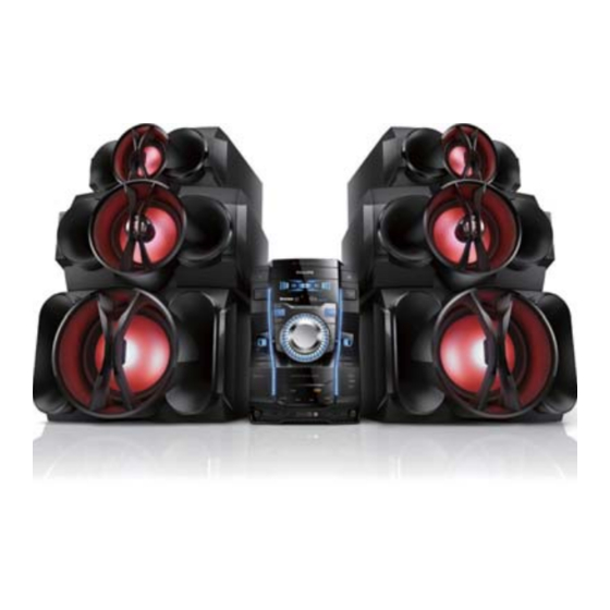
Mini Hi-Fi System
TABLE OF CONTENTS
Technical specification ...........................................................1-16
Safety instruction......................................................................2-1
ESD protection..........................................................................2-4
Set Block diagram ....................................................................3-1
Set Wiring diagram ...................................................................4-1
Disassembly diagram ...............................................................5-1
Main board
Display
CD
MCU
AMP
Tuner
Mechanical Exploded view......................................................12-1
©
Copyright 2013 Philips Consumer Electronics B.V. Eindhoven, The Netherlands
All rights reserved. No part of this publication may be reproduced, stored in a retrieval system or
transmitted, in any form or by any means, electronic, mechanical, photocopying, or otherwise without
the prior permission of Philips.
317
Published by LX 1
Service Audio
Version 1.0
Circuit diagram........................................................................6-1
Layout diagram.......................................................................6-2
board
Circuit diagram........................................................................7-1
Layout diagram.......................................................................7-2
board
Circuit diagram........................................................................8-1
Layout diagram.......................................................................8-2
board
Circuit diagram........................................................................9-1
Layout diagram.......................................................................9-2
board
Circuit diagram.............................................................10-1..10-2
Layout diagram......................................................................10-3
board
Circuit diagram......................................................................11-1
Layout diagram.....................................................................11-2
Printed in The Netherlands
Page
Subject to modification
FWT9200/
all
3140 038 60210
Advertisement

Related Manuals for Philips FWT9200 Series


Summary of Contents for Philips FWT9200 Series
- Page 1 Mechanical Exploded view............12-1 © Copyright 2013 Philips Consumer Electronics B.V. Eindhoven, The Netherlands All rights reserved. No part of this publication may be reproduced, stored in a retrieval system or transmitted, in any form or by any means, electronic, mechanical, photocopying, or otherwise without the prior permission of Philips.
- Page 2 1 - 2 Technical Specification and Connection Facilities Location of PC Boards CD PART CD Board Tuner Board Display Board Main Board BT Board Key Board MCU Board Light Board USB Board EQ Board AC Cord MIC/PC IN/AUDIO IN Board SMPS Board Amp Board VERSION VARIATION...
- Page 3 1 - 3 FWT9200 SH 190 content List Descrpitopn Page Issue: Andy Lai Checked: DATE: 2012-12-21...
- Page 4 DEPICTION Description Page DISC CHANGE 3 4 5 DISC1 DISC2 DISC3 OPEN/CLOSE |<TITLE PRESET TITLE>|PRESET >||(PLAY/PAUSE) PROGRAM/TIMER TUNER IR LENS AUX/LINE DISPLAY MIC VOL MIC 1 JACK MIC2 JACK ECHO VOL ROCK OTPIMAL MAX SOUND TECHNO JAZZ USB RECORD LINE IN USB JACK USB DEL USB DEL...
- Page 5 1 - 5 DEPICTION Description Page A.M. Antenna F.M. Anntena Aux Input for subwoofer AC INTPUT voltoge selector LOW /HIGH Left / Right Speaker Socket sub FAN SUB Aux Input 11 SUB voltoge selector 12 LS RS Speaker Socket 13 for MAIN 14 POWER SW CABINET Diemensions with Boxes ( wxhxd )265mm X 382 mm X 345 mm...
- Page 6 Tested according to General Test Instruction refer to PHILIPS standary ( UAN -D1591 ) Measured according to PHILIPS standary ( UAN - L1059 ) unless other wise stated All not mentioned date, please refer to PHILIPS standary ( XUW - 0010 - JUNE 2001 ) DERIVED...
- Page 7 1 - 7 TECHNIAL DESCRIPTION Total power 1800W, matching LOUDSPEAKER of 4 x 8 Ohm +2 x 4 Ohm. INPUT SOURCE, CD/MP TUNER USB AUX 3DSC ( Digital Sound Control ). IS ( Incredible Sound ) GENERAL PART OUTPUT stage Protection : Yes Temperature : Yes.
- Page 8 1 - 8 AUDIO SIGNAL PROCESSING MP3-USB Mini Hi Fi System with Digital Tuner , 3 CDC-MP3,(Main:2×3+60W+Rear:2×180W+SUB:2x360W) Universal Class D Power Amplifier DSC ( Digital Sound Control ) Select AUX as input source with the following set conditions: Inject sine wave 500mV at 1 KHz to L/R channels of AUX-IN socket. Set DSC to JAZZ(Flat) mode and switch off DBB.
- Page 9 1 - 9 AUDIO SIGNAL PROCESSING MP3 - USB Mini Hi Fi System with Digital Tuner , 3 CDC-MP3, (Main:2×360W+SUB:2×360W+Rear:2x180W) Universal Class D Power Amplifier IS ( Incredible Sound ) Select AUX as input source. Inject sine wave 2V at 1kHz to AUX-IN socket, two channel at a time (input level 600mV for /37,2V for /55 ). Set DSC to JAZZ ( Flat ) mode and switch of DBB, OSM &...
- Page 10 1-10 TECHNIAL DESCRIPTION SOFTWARE IMPLEMENTED CLOCK / TIMER FUNCTION WITH 12MHZ QUARTZ OSCILLATOR. GENERAL PART Timer Setting Clock and Timer Timer Wakeup Mode CD or Tuner or USB Remarks Time Setting 12hr for /37 version, 24hrs for other version. Volume at Wakeup Last Setting Nom : 1 sec/day Limit...
- Page 11 1 - 11 TECHNIAL DESCRIPTION See also SH 190 USB Audio Module (300605) Measurment are directly done at the coonector on the board GENERAL PART Measurement are directly done at the connector on CDC board Description Specification Output Resistance < = 1.5 kOhm Output Voltage RL = 33 k ohm ( )dB, 1 Khz ) 830mV/- 1dB Channel Unbalance...
- Page 12 1 - 12 TECHNIAL DESCRIPTION TUNER used SI4730 soultion GENERAL PART WAVE RANGE TOLERANCE TUNING GRID FM( 55/37 ) 87.5 - 108.00 MHz QUARTZ PRECISION 100 kHz FM( 12 ) 87.5 - 108.00 MHz 50KHZ AM (55/37) 530 - 1700 QUARTZ PRECISION 10 kHz AM (12)
- Page 13 1 - 13 TECHNIAL DESCRIPTION CD + MP3 - Part Specifications (CD MECHAISM DA11VF OF SANYO ) Input Output Motor Logic control Active components Signal processsing D/A converter HF-preamplifier Servo processor Active components AUDIO part: Measurement with Audio Signals Disc-783 7104 078 04911 on spkeakers or Headphone socket with nom.load Description Extern Filter Unit...
- Page 14 1 - 14 TECHNIAL DESCRIPTION Bluetooth Function GENERAL PART Bluetooth Version : Ver2.1 + EDR Receive A2DP: Transmit A2DP: Remote Controlled Receive HSP Noise Reduction System INDICATORS Bluetooth Flashing Display ELECTRICAL DATA Bluetooth at Module level: Mobile Phone Unit Frequency Response 125-16khz S/N (Unweighted) S/N (A-weighted)
- Page 15 1 - 15 TECHNIAL DESCRIPTION Microphone See also SH 190 testing with 20 to 20k Hz filter,input leven 1mv rms(lim:1.5mv rms) Rs=600ohm output 500mW Measurment are directly done at the coonector on the board GENERAL PART Measurement are directly done at the connector Microphone(mic1,mic2) Description Specification Unit...
- Page 16 1 - 16 VERSION OVERVIEW FWT9200 APPROBATION TUNER AC SUPPLY DEST SURR MAINS SAFETY Wave RANGE GRID AERIAL SOCKET AERIAL SUPPLIED SOC. CORD . SPK. VOLTAGE EN60065 110-127V FM 87.5-108MHz MW 50kHz CLASS II 75 Ohm Coaxial 75 Ohm Pigtail Switched /55 /77/78/98 CISPR 13...
- Page 17 2.0 SAFTETY INSTRUCTIONS WAARSCHUWING WARNING Alle IC’s en vele andere halfgeleiders zijn All ICs and many other semi-conductors are gevoelig voor electrostatische ontladingen susceptible to electrostatic discharges (ESD). (ESD). Careless handling during repair can reduce life Onzorgvuldig behandelen tijdens reparatie kan drastically.
- Page 18 2.1 ESD PROTECTION When the power supply is being turned on, you may not remove this laser cautions label. If it removes, radiation of laser may be received. PREPARATION OF SERVICING Pickup Head consists of a laser diode that is very susceptible to external static electrocity. Although it operates properly after replacement, if it was subject to electrostatic discharge during replacement, its life might be shortened.
- Page 19 SAFTY NOTICE SAFTY PRECAUTIONS LEAKAGE CURRENT CHECK Plug the AC line cord directly into a 120V AC outlet (do Measure the AC voltage across the 1500 resistor. not use an isolation transformer for this check). Use an The test must be conducted with the AC switch on and AC voltmeter, having 5000 per volt or more sensitivity.
- Page 20 2.2 SAFETY INSTRUCTIONS Battery Handling Guideline Since the battery is packed in soft package, to ensure its good performance, it’s very important to carefully handle the battery 2.2.1 Soft Aluminium foil The soft aluminum packing foil is very easily damaged by sharp edge parts such as Ni-tabs, pins and needles. •...
- Page 21 BLOCK DIAGRAM VFD Board CD Board CD DOOR MOTOR VFD Display TUNER AC CORD (SI4730/31 ) VFD DRIVER LED DRIVER 3CD LOADER PT6311 BU2090F POWER Board MOTOR DRIVER CD DOOR AM5888S DRIVER IC PICK UP TA7291S FWM998/ FWM9000 8M SERIAL For 1000W FALSH MOTOR...
- Page 22 WIRING DIAGRAM...
- Page 23 OUTER 1)Remove 10 screws A and 10 screws B/C as indicated to loosen the outer plate. CD PART REAR PLATE OUTER PLATE FRONT CAB. BOTTOM PLATE Dismantling of the CD part and Bottom plate and PCB Board 1)Remove 2 screws D as indicated to loosen the CD part. 2)Remove 2 screws E and 3 screws F as indicated to loosen the Bottom Plate.
- Page 25 PCB LAYOUT - MAIN BOARD...
- Page 26 CIRCUIT DIAGRAM - DISPLAY BOARD...
- Page 27 PCB LAYOUT - DISPLAY BOARD...
- Page 28 CIRCUIT DIAGRAM - CD BOARD GPIO193 GPIO194 GPIO195 R535 R533 C536 3U3/50v CD-R This GND must be C520 100n C532 R536 C533 use AGND 470P C519 100u/16v 470P T1 T1 C534 C531 R537 470P 470P R531 R534 C535 3U3/50v CD-L C511 R530 220R...
- Page 29 PCB LAYOUT - CD BOARD...
- Page 30 CIRCUIT DIAGRAM - MCU BOARD...
- Page 31 PCB LAYOUT - MCU BOARD...
- Page 32 10-1 10-1 CIRCUIT DIAGRAM - AMP BOARD R7162 TO SMPS PB OSC1 R7164 CN701 +40V R732 U706 22UF/100V C760 Y702 +12V 700KHZ FB1K8 FB1K8 -40V R731 L721 L722 104P U701 C7227 C743 74CTO4 100P R7154 C758 104P R745 C747 C757 R747 C745 330PF...
- Page 33 10-2 10-2 CIRCUIT DIAGRAM - AMP BOARD 22UF/100V C7126 SUB-ON/OFF-CTL R782 104P C7231 U703 C7124 104P C7123 C7132 680N C7122 8 IN1+ BOOT1 IN1- OUT1 SPK3A L705 VSSA3 OSCREF 15UH TDA8954TH SGND OUT2 8 OHM C7121 IN2+ BOOT2 15UH R768 R775 R777 R779...
- Page 34 10-3 10-3 PCB LAYOUT - AMP BOARD...
- Page 35 11-1 11-1 CIRCUIT DIAGRAM - TUNER BOARD...
- Page 36 11-2 11-2 PCB LAYOUT - TUNER BOARD...
- Page 37 12-1 12-1 EXPLODED VIEW...