Philips PET1031 Service Manual
Hide thumbs
Also See for PET1031:
- Specifications (3 pages) ,
- User manual (30 pages) ,
- Quick start manual (2 pages)
Table of Contents
Advertisement
Quick Links
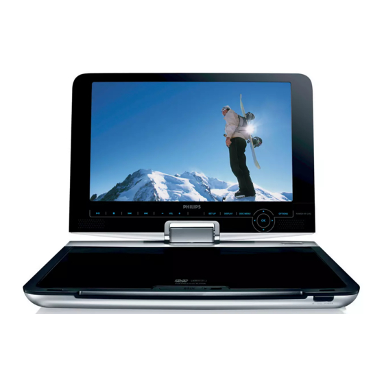
DVD Portable Player
Service Manual
TABLE OF CONTENTS
Technical Specification & Service Tips......................... 1
Safety Instructions..................................................... 2
Instruction for Use...................................................... 3
Mechanical Instructions.............................................. 4
Troubleshooting .........................................................5
Overall Block Diagram................................................. 6
Overall Wiring Diagram................................................7
Electrical Diagram...................................................... 8
Component Layout.................................................... 9
Service Part List......................................................... 10
Revision List............................................................. 11
©Copyright 2005 Philips Consumer Electronics B.V. Eindhoven, The Netherlands
All rights reserved. No part of this publication may by reproduced, stored in a
retrieval system or transmitted, in any form or by any means, electronics,
mechanical, photocopying, or otherwise without the prior permission of Philips
FK0946
Version 1.4
PET1031
All version
Chapter
3141 785 32254
Advertisement
Table of Contents

Related Manuals for Philips PET1031


Summary of Contents for Philips PET1031
-
Page 1: Table Of Contents
All rights reserved. No part of this publication may by reproduced, stored in a retrieval system or transmitted, in any form or by any means, electronics, mechanical, photocopying, or otherwise without the prior permission of Philips FK0946 3141 785 32254... - Page 2 1.0 TECHNICAL SPECIFICATION Playback disc type: DVD, Picture-CD, General SVCD, Video CD, MP3- CD, CD-R/CD-RW, WMA-CD, DVD-R, DVD- Dimensions (W x H x D): 204 x 168 x 33 mm RW, DVD+R, DVD+RW Weight: 1.0kg Power supply: DC 9V 1.8A Power consumption: Video Playback Format: DVD / VCD / JPEG...
- Page 3 For the best performance of your DVD Portable. Check www.philips.com/support for latest software upgrades available. Download the latest software from the Philips support site Region code “0” can be used for all regions! Unzip the files and then burn it into a CD-ROM to...
- Page 4 2.0 SAFTETY INSTRUCTIONS WAARSCHUWING WARNING Alle IC’s en vele andere halfgeleiders zijn All ICs and many other semi-conductors are gevoelig voor electrostatische ontladingen susceptible to electrostatic discharges (ESD). (ESD). Careless handling during repair can reduce life Onzorgvuldig behandelen tijdens reparatie kan drastically.
- Page 5 2.1 ESD PROTECTION When the power supply is being turned on, you may not remove this laser cautions label. If it removes, radiation of laser may be received. PREPARATION OF SERVICING Pickup Head consists of a laser diode that is very susceptible to external static electrocity. Although it operates properly after replacement, if it was subject to electrostatic discharge during replacement, its life might be shortened.
- Page 6 SAFTY NOTICE SAFTY PRECAUTIONS LEAKAGE CURRENT CHECK Plug the AC line cord directly into a 120V AC outlet (do Measure the AC voltage across the 1500 resistor. not use an isolation transformer for this check). Use an The test must be conducted with the AC switch on and AC voltmeter, having 5000 per volt or more sensitivity.
-
Page 7: Instruction For Use
3.0 INSTRUCTIONS FOR USE DVD PLAYER LAYOUT POWER Switches the player on / off. Start / pause / resume playback. CHR/IR/POWER Press once to stop playback Power /remote sensor /charging and store the stop position. indicator. Press twice to stop playback RESET completely. - Page 8 REMOTE CONTROL MENU SUBTITLE Display MENU page. Subtitle language selector. , , , RETURN Up / down / left / right For VCD menu page. navigation key. A - B To repeat or loop a sequence Confirm seletion. in a title. VOL +/- SETUP Volume control.
- Page 9 4.0 MECHNICAL INSTRUCTIONS 5. Rotate the top and remove screws to break 1. Side view as Fig.1 the top and the base away as Fig.5. Remove base cover adorn discreteness as Fig.1. Fig.1 Fig.5 6. Broken connection of DVD driver to remove 2.
- Page 10 4.0 MECHNICAL INSTRUCTIONS 9. Remove speaker grill as Fig.9. Fig.9 10. Remove screws to remove top cover discreteness as Fig.10. Fig.10 11. Remove screws and broken connection to remove IF board and LED driver board as Fig.11. Fig.11 Remove LCD TFT and function board as Fig.12. Fig.12...
-
Page 11: Mechanical Instructions
4.0 MECHANICAL INSTRUCTIONS Close up on the connectivity of 996510006526 & 996510003961... -
Page 12: Troubleshooting
1. Power on player and open DVD Door. 2. Press <Set Up> at Remote Control. In <Set Up Menu> select <Preferences>. 3. For PET1031 - Press successively 2 1 2 2 2 5. . . 4. Display will show <Region Code 2> for Europe: 5. - Page 13 5.0 TROUBLESHOOTING & SERVICE TIPS SYMPTOM: NO POWER, NO GREEN LED start Check if the power cable replace cable/ No defect, return set OK? adapter set to customer AC adapter Check if the replace connector power and play and switch unit button OK? replace MAIN go to other...
- Page 14 5.0 TROUBLESHOOTING & SERVICE TIPS SYMPTOM: THE INITIAL SCREEN IS NOT DISPLAYED ON THE LCD Refer to the symptom NO start POWER, NO GREEN LED Replace broken Check if the Repair connector harness LED on the front lights up? Remove the LCD Open the top and Is the cover and plate of...
- Page 15 5.0 TROUBLESHOOTING & SERVICE TIPS SYMPTOM: THE DVD DRIVE DOES NOT WORK Press the DISC cover switch at the center of the DVD player and turn on the power. Then check whether or not the optical pick- up lens of the DVD drive lights. CAUTION: start Visible laser radiation when open and interlock defeated.
- Page 16 5.0 TROUBLESHOOTING & SERVICE TIPS SYMPTOM: THE DVD DRIVE DOES NOT OPERATE WITH BATTERY start Install a good battery does the LED lights up orange while the AC adapter is connected and does the DVD drive operate OK? NOTE: - For this check, use a battery which is not fully Replace battery charged (because the LED does not light when the battery is fully charged.)
-
Page 17: Overall Block Diagram
6.0 OVERALL BLOCK DIAGRAM AT1313 16M FlashROM 64M SDRAM TC4W53 74HCU04 27MHz KH29LV160CBTC-70G HY57V641620ETP-7-C TFT MONITOR RF AMP & SERVO & DVD PROCESSOR DV23 MPEG-2 DECODER & VIDEO ENCODER PU mechanism MT1389DXE/P-L SD.MMC.MS.CARD +3.3V +1.8V COMP.OUT S VIDEO DRIVER DRIVER +5V (BA5888) COAXIAL OUT VIDEO OUT... -
Page 18: Overall Wiring Diagram
7.0 OVERALL WIRING DIAGRAM POWERKEY PCB BATTERY PROTECTIVE PCB VCOM BATT+ BATT+ BATT+ CD/DVDSW MAIN PCB IF PCB VCOM STHL 3V3P LD/CD LD/DVD 3V3P EDGSL STVR VRDVD VR/CD KEYAD1 KEYAD0 LIMIT LED DRIVER PCB LOADING FUNCTION BUTTON PCB... -
Page 19: Electrical Diagram
8.0 ELECTRICAL DIAGRAM - MAIN BOARD CIRCUIT DIAGRAM(MT1389P) XTALI XTALO 100K 100K CB27 CB27 C139 C139 C140 C140 100N 100N 10U/10V 10U/10V AVDD33_VFE DV33 601H 601H CB30 CB30 CB28 CB28 100N 100N RFV18 100N 100N 10U/10V 10U/10V AVDD33_DMPLL 601H 601H DV33 601H 601H... - Page 20 8.0 ELECTRICAL DIAGRAM - MAIN BOARD CIRCUIT DIAGRAM (AUDIO) VD43 VD43 ISS355 ISS355 TFTON R133 R133 C133 C133 22U/16V 22U/16V +P5V R168 R168 VD40 VD40 DTC124 DTC124 VD45 VD45 VD25 VD25 R158 R158 STZ6.2N STZ6.2N ISS355 ISS355 C122 C122 ISS355A ISS355A 100P 100P...
- Page 21 8.0 ELECTRICAL DIAGRAM - MAIN BOARD CIRCUIT DIAGRAM(DRIVER) +P5V C179 C179 C177 C177 C165 C165 10U/10V 10U/10V 100P 100P RF3V3 DV33 CB49 CB49 C146 C146 C175 C175 10U/16V 10U/16V 100N 100N 10U/10V 10U/10V C170 C170 C174 C174 CB46 CB46 100P 100P 100N 100N...
- Page 22 8.0 ELECTRICAL DIAGRAM - MAIN BOARD CIRCUIT DIAGRAM(POWER & CHARGE) C121 C121 100U/16V 100U/16V PVDD1 PVDD2 C154 C154 C156 C156 BOOT1 BOOT2 R128 R128 10UH 10UH 10UH 10UH 3.8V 5.5V 100K 100K VD34 VD34 UDZ1715B UDZ1715B C153 C153 C150 C150 CB109 CB109 F002...
- Page 23 8.0 ELECTRICAL DIAGRAM - IF BOARD CIRCUIT DIAGRAM TFTON/OFF 3V3P 3V3P BRIGHTCON 3V3P SPL+ SPL- STVR STVD SPR- SPR+ R130 R130 STVL STVU #EDGSL EDGSL VCC=3.3V STHL STHL R131 R131 VGL=-10V CPU3.3V CPU3.3V VGH=+15V VCC=3.3V STVL KEYAD0 STHR STHR STVR KEYAD1 LD(OEH) TO KEY BOARD...
-
Page 24: Component Layout
9.0 COMPONENT LAYOUT PET1031M MAIN BOARD DIAGRAM (TOP) PET1031M MAIN BOARD DIAGRAM (BOTTOM) - Page 25 9.0 COMPONENT LAYOUT PET1031 LED DRIVER BOARD DIAGRAM PET1031T IF BOARD DIAGRAM PET1030K FUNCTION BOARD DIAGRAM...
-
Page 26: Service Part List
PCB ASSY/12 PET1031M MAIN PET1031/93 996510012441 PCB ASSY/93 PET1031M MAIN PET1031/98 996510012440 PCB ASSY/98 PET1031T IF PCB PET1031 996510009913 ASSY PET1031 LED PET1031 996510009914 DRIVER PCB ASSY PET1030K PET1031 996510003964 FUNCTION PCB ASSY PET1030 POWER PET1031 996510005764 KEY PCB ASSY... - Page 27 Service Description Photo Pos. 12NC PET1031 996510009915 AT102TN03 TFT LCD PET1031 996510004977 DV23FC LOADING ASS’Y PET1031 994000002165 YD1635-2 SPEAKER PET1031 996510003967 TOP COVER PET1030 DISPLAY FRAME PET1031 996510003968 PET1030 DOOR + MIDDLE PET1031 996510003969 CABINET PET1030 PET1031 996510009919 BASE COVER PET1031...
- Page 28 10.0 SERVICE PART LIST Mechanical Part List: Service Service Description Photo Pos. 12NC BASE COVER ADORN PET1031 996510006727 DISCRETENESS PET1031 996510006728 PET1030 SPEAKER SKILL PET1031 996510003972 ADJUST HINGE PET1030 LENS REMOTE SENSOR PET1031 996510003973 PET1030...
- Page 29 10.0 SERVICE PART LIST Accessories Part List: Service Service Photo Pos. No. 12NC Description ADPV26A AC PET1031/12 996510009918 POWER PET1031/98 ADAPTOR/00 ADAPTOR ADPV26A AC PET1031/93 996500042048 POWER ADAPTOR/93 PET1031 996510001124 CIGARETTE CARADAPTOR ADAPTER PET1031 994000001912 AV CABLE AVCABLE CHROMATISM PET1031...
-
Page 30: Revision List
Version 1.0 (3141 785 32250) • Initial release PET1031/12 Version 1.1 (3141 785 32251) • Section 10 - Add spare part for PET1031/93, PET1031/98 Version 1.2 (3141 785 32252) • Section 8 – Update electrical diagram Version 1.3 (3141 785 32253) •...