Lenovo RackSwitch G8332 Installation Manual
Hide thumbs
Also See for RackSwitch G8332:
- Command reference manual (776 pages) ,
- Installation manual (122 pages)
Table of Contents
Advertisement
Quick Links
Advertisement
Table of Contents

Related Manuals for Lenovo RackSwitch G8332


Summary of Contents for Lenovo RackSwitch G8332
- Page 1 Lenovo RackSwitch G8332 Installation Guide...
- Page 2 (LAMC) document on the Documentation CD and the Systems Environmental Notices and Users Guide document on the Environmental Notices CD. © Copyright 2015 Lenovo US Government Users Restricted Rights—Use, duplication or disclosure restricted by GSA ADP Schedule Contract with Lenovo. January 2015 Edition...
-
Page 3: Safety Information
Prima di installare questo prodotto, leggere le Informazioni sulla Sicurezza. Πред да инсталира овој продукт, прочитајте информацијата за безбедност. Les sikkerhetsinformasjonen (Safety Information) før du installerer dette produktet. Przed zainstalowaniem tego produktu, należy zapoznać się z książką “Informacje dotyczace bezpieczeństwa” (Safety Information). © Copyright 2015 Lenovo Safety Information... - Page 4 Antes de instalar este producto, lea la información de seguridad. Läs säkerhetsinformationen innan du installerar den här produkten. Bu ürünü kurmadan önce güvenlik bilgilerini okuyun. Youq mwngz yungh canjbinj neix gaxgonq, itdingh aeu doeg aen canjbinj soengq cungj vahgangj ancien suisik. RackSwitch G8332 Installation Guide...
-
Page 5: Safety Statements
Laser radiation when open. Do not stare into the beam, do not view directly with optical instruments, and avoid direct exposure to the beam. Class 1 Laser Product Laser Klasse 1 Laser Klass 1 Luokan 1 Laserlaite Appareil À Laser de Classe 1 © Copyright 2015 Lenovo Safety Information... - Page 6 Overloading a branch circuit is potentially a fire hazard and a shock hazard under certain conditions. To avoid these hazards, ensure that your system electrical requirements do not exceed branch circuit protection requirements. Refer to the information that is provided with your device for electrical specifications. RackSwitch G8332 Installation Guide...
- Page 7 Statement 25 CAUTION: This product contains a Class 1M laser. Do not view directly with optical instruments. Statement 26 CAUTION: Do not place any object on top of rack-mounted devices. © Copyright 2015 Lenovo Safety Information...
- Page 8 4. Attach signal cables to other 2. Remove the signal cables from the devices. connectors. 5. Connect power cords to their 3. Remove all cables from the sources. devices. 6. Turn ON all the power sources. RackSwitch G8332 Installation Guide...
-
Page 9: Other Important Safety Notices
Multiple devices extended into the service position can cause your rack cabinet to tip. • If you are not using the Lenovo 9308 rack cabinet, securely anchor the rack cabinet to ensure its stability. Other Important Safety Notices Important This product is also designed for IT power distribution systems with phase-to-phase voltage of 230V. - Page 10 RackSwitch G8332 Installation Guide...
-
Page 11: Table Of Contents
Other Important Safety Notices ....9 Chapter 1. The RackSwitch G8332 ....15 Introduction . - Page 12 Removing the G8332 from a Lenovo System x or Power Rack..62 Removing the G8332 from a Lenovo iDataPlex Rack ..65 Removing the 1U Air Duct Option ....67 Replacing the G8332 .
- Page 13 Power Specifications ..... . . 88 Switching Performance ..... . 88 © Copyright 2015 Lenovo Contents...
- Page 14 RackSwitch G8332 Installation Guide...
-
Page 15: Chapter 1. The Rackswitch G8332
The console output described or referenced in this document might differ slightly from that displayed by your system. Output varies according to the type of Lenovo chassis and the firmware versions and options that are installed. © Copyright 2015 Lenovo... -
Page 16: Notices And Statements In This Document
If you are using a Linux operating system, insert the CD into the CD or DVD drive and run the following command from the mnt/cd directory: sh.linux.sh When the CD is mounted, open the directories and documents that support your product. RackSwitch G8332 Installation Guide... -
Page 17: Related Documentation
Related Documentation Additional or updated product documents may be available from the Lenovo website. Such documents may cover features not described in the original documentation that comes with the switch, or may include technical updates or corrections. You can obtain up-to-date information on the Lenovo support website: http://support.lenovo.com/... - Page 18 RackSwitch G8332 Installation Guide...
-
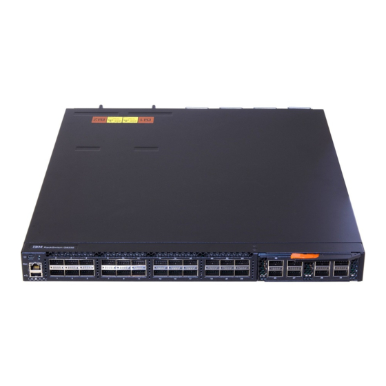
Page 19: Chapter 2. Switch Components
The following illustrations show the features on the front and rear of the switch. Figure 1. RackSwitch G8332 front panel Management QSFP+ Ports MDA Module Panel QSPF+ Ports Figure 2. RackSwitch G8332 management panel detail Mini-USB Reset Button Serial Console Port RJ-45 Management Port USB Port Status LEDs Figure 3. -
Page 20: Management Panel
Table 2. Console cable RJ-45 port connector pin assignments Pin Number Function RTS (Request To Send) DTR (Data Terminal Ready) TxD (Transmit Data) GND (Ground) GND (Ground) RxD (Receive Data) DSR (Data Set Ready) CTS (Clear To Send) RackSwitch G8332 Installation Guide... -
Page 21: Rj-45 Management Port
Normal reset—Press and release Reset. The switch resets and reloads the configuration files. • Factory reset—Press and hold Reset for more than five seconds. The switch resets and reverts all configuration settings to the factory defaults. © Copyright 2015 Lenovo Chapter 2: Switch Components... -
Page 22: System Status Leds
(DACs), including those that allow the port to be used as four 10 GbE SFP+ ports. The switching ports are described in the following sections. For information about ports on the management panel, see “Management Panel” on page RackSwitch G8332 Installation Guide... -
Page 23: Qsfp+ Ports
QSFP+ optical transceiver with MTP-to-4 LC (SFP+) fiber breakout cable. This option supports only Lenovo 10GBASE-SR SFP+ transceivers. The 40GBASE-SR4 specification (802.3ba-2010) indicates a higher optical power level than standard 10GBASE-SR. Lenovo SFP+ SR transceivers can handle the higher optical power levels. This cable must be purchased separately. •... - Page 24 QSFP+ LEDs Status LEDs for the QSFP+ ports are described in the following table. Table 5. QSFP+ port status LED behavior Steady Green Flashing Green Link up Activity No Link RackSwitch G8332 Installation Guide...
-
Page 25: Rear Panel
The device also might have more than one power cord. To remove all electrical current from the device, ensure that all power cords are disconnected from the power source. © Copyright 2015 Lenovo Chapter 2: Switch Components... - Page 26 4. Attach signal cables to other 2. Remove the signal cables from the devices. connectors. 5. Connect power cords to their 3. Remove all cables from the sources. devices. 6. Turn ON all the power sources. RackSwitch G8332 Installation Guide...
- Page 27 Power supply is operational. Green DC output power is present. DC output power is OK. Green AC power is OK. No power. Output is disabled, or input power is outside operating range. © Copyright 2015 Lenovo Chapter 2: Switch Components...
- Page 28 RackSwitch G8332 Installation Guide...
-
Page 29: Chapter 3. Installing G8332 Hardware And Options
– “Installing the G8332 in a Standard Equipment Rack” on page 35 – “Installing the G8332 in a Lenovo System x or Power Rack” on page 37 – “Installing the G8332 in a Lenovo iDataPlex Rack” on page 41 •... -
Page 30: Before Installing The G8332
Print this page and record product information below. Keep the information in a safe place for future reference. You will need this information when you register the switch or open a service call with Lenovo. Table 8. Important product information... -
Page 31: Required Tools
Electrostatic discharge wrist strap Package Contents The basic G8332 package contains the following items: • One RackSwitch G8332 unit with front-to-rear or rear-to-front airflow • One two-post mounting kit for standard 19” equipment racks: – Two mounting brackets – Screws to attach brackets to the switch unit –... - Page 32 Power cords for this product for a specific country or region are usually available only in that country or region. Power cord installation should also conform to the recommendations listed in “Cabling Guidelines” on page RackSwitch G8332 Installation Guide...
- Page 33 2. Remove the signal cables from the devices. connectors. 5. Connect power cords to their 3. Remove all cables from the sources. devices. 6. Turn ON all the power sources. © Copyright 2015 Lenovo Chapter 3: Installing G8332 Hardware and Options...
-
Page 34: Handling Static-Sensitive Devices
Make sure that the radius of any bend does not exceed the vendor recommended minimum bend radius. • Do not stress cables and connectors by applying additional twists, tension beyond load ratings, stapling, or applying nylon tie-wraps with a tie-wrap puller. RackSwitch G8332 Installation Guide... -
Page 35: Installing The G8332 In A Rack
® • For a Lenovo System x or Power 4-post rack, such as the Lenovo e1350, use the Lenovo Adjustable 19” 4-Post Rail Kit. This kit must be purchased separately. Installation instructions begin on page ® • For a Lenovo iDataPlex rack, use the iDataPlex mounting kit. - Page 36 Torque the screws to approximately 5.7 Nm ± 0.1 Nm (50 inch-pounds). 5. If installing the 1U air duct option, see the instruction on page 6. Connect all external cables in accordance with the “Cabling Guidelines” on page RackSwitch G8332 Installation Guide...
-
Page 37: Installing The G8332 In A Lenovo System X Or Power Rack
This section describes how to install the G8332 in a Lenovo System x or Power 4-post rack, such as the Lenovo e1350, using the Lenovo Adjustable 19” 4-Post Rail Kit. The kit must be purchased separately. It includes the following parts: Table 10. - Page 38 2. Remove the rear cover screws: 3. Use M4 screws to attach the front mounting brackets to each side of the switch. Torque the screws to approximately 2.0 newton-meters (Nm) ± 0.1 Nm (17.7 inch-pounds). RackSwitch G8332 Installation Guide...
- Page 39 Torque the screws to approximately 5.7 Nm ± 0.1 Nm (50 inch-pounds). 5. Slide the rear mounting brackets into the slots available on the front mounting brackets. © Copyright 2015 Lenovo Chapter 3: Installing G8332 Hardware and Options...
- Page 40 “Cabling Guidelines” on page 10. Initialize the switch. See Chapter 5, “Initializing the G8332,” on page 11. If the switch is a replacement unit, set Vital Product Data (see “Configuring Vital Product Data” on page 68). RackSwitch G8332 Installation Guide...
-
Page 41: Installing The G8332 In A Lenovo Idataplex Rack
Installing the G8332 in a Lenovo iDataPlex Rack This section describes how to install the G8332 in a Lenovo iDataPlex rack. The iDataPlex mounting kit allows the switch to be mounted either horizontally or vertically. The kit must be purchased separately. It includes the following parts: Table 11. - Page 42 2. Remove the rear cover screws: 3. Use the M4 screws to attach front and rear mounting brackets to each side of the switch. Torque the screws to approximately 2 newton-meters (Nm) +/- 0.1 Nm (17.7 inch-pounds). RackSwitch G8332 Installation Guide...
- Page 43 9. Initialize the switch. See Chapter 5, “Initializing the G8332,” on page 10. If the switch is a replacement unit, set Vital Product Data (see “Configuring Vital Product Data” on page 68). © Copyright 2015 Lenovo Chapter 3: Installing G8332 Hardware and Options...
-
Page 44: Installing The 1U Air Duct Option
Table 12. 1U air duct mounting kit Item Number Description Quantity Cable tie 1U Duct sleeve (long) Mounting bracket, right, assembly, 1U duct Mounting Bracket, left, assembly, 1U duct Foam carrier assembly, including half-shears Screw, slotted, M3.5, 7 mm, flanged hex head RackSwitch G8332 Installation Guide... - Page 45 G8332 unit. Torque the screws to approximately 1.1 Nm ± 0.1 Nm (10 inch-pounds). Foam carrier snug against rear of unit Reuse mounting screws Half shear Mounting screws Note: There are additional M3.5 screws in the air duct assembly kit. © Copyright 2015 Lenovo Chapter 3: Installing G8332 Hardware and Options...
- Page 46 Air duct mounting bracket M6 screws M3.5 screws 5. Use the M3.5 screws to secure the air duct mounting bracket to the rack chassis. Torque the screws to approximately 1.1 Nm ± 0.1 Nm (10 inch-pounds). RackSwitch G8332 Installation Guide...
- Page 47 Make sure that the foam strip is oriented on top. Foam Card guides thumbscrews Side flanges 7. Use the two M4 thumbscrews to secure the air duct unit to the air duct brackets. © Copyright 2015 Lenovo Chapter 3: Installing G8332 Hardware and Options...
-
Page 48: Installing Port Transceivers
4. Connect the cable following the “Cabling Guidelines” on page To remove an SFP copper transceiver, disconnect the cable, and pull down the locking lever to release the transceiver. After you remove the transceiver, replace the safety cap. RackSwitch G8332 Installation Guide... -
Page 49: Installing An Sfp Optical Transceiver
The transceiver has a mechanical guide key to prevent you from inserting the transceiver in an incorrect orientation. 3. Pull up the locking lever to lock the transceiver into place. © Copyright 2015 Lenovo Chapter 3: Installing G8332 Hardware and Options... -
Page 50: Installing An Sfp+ Optical Transceiver
Laser radiation when open. Do not stare into the beam, do not view directly with optical instruments, and avoid direct exposure to the beam. Class 1 Laser Product Laser Klasse 1 Laser Klass 1 Luokan 1 Laserlaite Appareil À Laser de Classe 1 RackSwitch G8332 Installation Guide... -
Page 51: Installing A Qsfp+ Optical Transceiver
Some laser products contain an embedded Class 3A or Class 3B laser diode. Note the following. Laser radiation when open. Do not stare into the beam, do not view directly with optical instruments, and avoid direct exposure to the beam. © Copyright 2015 Lenovo Chapter 3: Installing G8332 Hardware and Options... - Page 52 4. Connect the fiber-optic cable following the “Cabling Guidelines” on page To remove a QSFP+ optical transceiver, disconnect the fiber-optic cable, and pull down the locking lever to release the transceiver. After you remove the transceiver, replace the safety cap. RackSwitch G8332 Installation Guide...
-
Page 53: Chapter 4. Removing And Replacing G8332 Components
– “Removing the G8332 from a Standard Equipment Rack” on page 61 – “Removing the G8332 from a Lenovo System x or Power Rack” on page 62 – “Removing the G8332 from a Lenovo iDataPlex Rack” on page 65 •... -
Page 54: Removing And Replacing A Power Supply Module
The device also might have more than one power cord. To remove all electrical current from the device, ensure that all power cords are disconnected from the power source. RackSwitch G8332 Installation Guide... - Page 55 Assistance” on page 77 to help you gather all the required information that is necessary to return a component. After you remove the component, securely pack the component for shipping. © Copyright 2015 Lenovo Chapter 4: Removing and Replacing G8332 Components...
-
Page 56: Replacing The Power Supply Module
4. Attach signal cables to other 2. Remove the signal cables from the devices. connectors. 5. Connect power cords to their 3. Remove all cables from the sources. devices. 6. Turn ON all the power sources. RackSwitch G8332 Installation Guide... - Page 57 3. Connect the power cord to the power supply module and to an appropriate universal grounded AC power source. 4. Make sure that the power supply module’s OK|DC and AC LEDs are green. © Copyright 2015 Lenovo Chapter 4: Removing and Replacing G8332 Components...
-
Page 58: Removing And Replacing A Fan Module
Appendix A, “Getting Help and Technical Assistance” on page 77 to help you gather all the required information that is necessary to return a component. After you remove the component, securely pack the component for shipping. RackSwitch G8332 Installation Guide... -
Page 59: Replacing The Fan Module
To turn the power off and remove the MDA module properly, complete the following steps. 1. Log into the switch. 2. To turn off the power to the MDA module, execute the following commands: RS G8332> enable RS G8332# mda shutdown © Copyright 2015 Lenovo Chapter 4: Removing and Replacing G8332 Components... -
Page 60: Replacing The Mda Module
2. Push the lock handle to secure the module in place. 3. Log into the switch. 4. To turn on the power to the MDA module, execute the following commands: RS G8332> enable RS G8332# no mda shutdown RackSwitch G8332 Installation Guide... -
Page 61: Removing The G8332 From A Standard Equipment Rack
5. Loosen and remove the M4 screws attaching the mounting bracket on each side of the switch. 6. If replacing the unit with another G8332, see “Replacing the G8332” on page © Copyright 2015 Lenovo Chapter 4: Removing and Replacing G8332 Components... -
Page 62: Removing The G8332 From A Lenovo System X Or Power Rack
Removing the G8332 from a Lenovo System x or Power Rack This section describes how to remove the G8332 from a Lenovo System x or Power 4-post rack, such as the Lenovo e1350. To remove the G8332 from a System x or Power rack, complete the following steps: 1. - Page 63 6. Loosen and remove the M6 screws, washers, and clip nuts are used to connect the front mounting brackets to the front and rear posts in the rack. 7. Slide the G8332 out of the rack. © Copyright 2015 Lenovo Chapter 4: Removing and Replacing G8332 Components...
- Page 64 8. Loosen and remove the M4 screws that attach the front mounting brackets to each side of the switch. 9. If replacing the unit with another G8332, see “Replacing the G8332” on page RackSwitch G8332 Installation Guide...
-
Page 65: Removing The G8332 From A Lenovo Idataplex Rack
Removing the G8332 from a Lenovo iDataPlex Rack This section describes how to remove the G8332 from a Lenovo iDataPlex rack. To remove the G8332 from an iDataPlex rack, complete the following steps: 1. Disconnect all external cables. 2. If the 1U air duct option has been installed, remove it as described in “Removing the 1U Air Duct Option”... - Page 66 6. Loosen and remove the M4 screws that attach front and rear mounting brackets to each side of the switch. 7. If replacing the unit with another G8332, see “Replacing the G8332” on page RackSwitch G8332 Installation Guide...
-
Page 67: Removing The 1U Air Duct Option
Removing the 1U Air Duct Option The G8332 supports an optional 1U air duct to maximize air flow conditions in a Lenovo Power Systems Group rack. To remove an installed 1U air duct option from a 19” rack, complete the following steps. -
Page 68: Replacing The G8332
71. At the Password prompt, the default password is admin. 2. Use the following CLI commands to enter the Executive configuration mode: RS G8332> enable Enable privilege granted RS G8332# configure terminal Enter configuration commands, one per line. End with Ctrl/Z. RS G8332 (config)# RackSwitch G8332 Installation Guide... - Page 69 System Information at 0:11:46 Wed Jan 6, 2015 Time zone: America/US/Pacific Daylight Savings Time Status: Disabled Lenovo RackSwitch G8332 Switch has been up for 0 days, 0 hours, 10 minutes and 45 seconds. Last boot: 0:11:36 Wed Jan 6, 2015 (reset from console) MAC address: fc:cf:62:9d:2b:00 IP (If 1) address: 192.168.49.50...
- Page 70 RackSwitch G8332 Installation Guide...
-
Page 71: Chapter 5. Initializing The G8332
You can access the switch CLI through the serial console port on the front panel of the switch. This port uses RS-232 serial communications. Use the console cable kit to connect the serial console port to a terminal or a computer running a terminal emulation program. © Copyright 2015 Lenovo... -
Page 72: Using The Management Port
However, if desired, you can revert the custom configuration settings to the original factory defaults. The original factory default configuration files are a permanent part of the firmware; you cannot deleted them or change their original definitions. RackSwitch G8332 Installation Guide... -
Page 73: Configuring An Ip Interface For Remote Access
In addition, you can configure the switch for management using an SNMP-based network management system or a web-browser. For more information about using the CLI, see the Command Reference guide for your specific switch and firmware version. © Copyright 2015 Lenovo Chapter 5: Initializing the G8332... -
Page 74: Updating Firmware
Updating Firmware If firmware updates are available, you can download them from the Lenovo website. The switch might have features that are not described in the documentation that comes with the switch, and the documentation might be updated occasionally to include information about those features, or technical updates might be available to provide additional information that is not included in the switch documentation. -
Page 75: Chapter 6. Troubleshooting
If you have problems accessing the switch or working with the firmware, see the Command Reference for the switch. For information about calling Lenovo for service, see Appendix A, “Getting Help and Technical Assistance”... - Page 76 RackSwitch G8332 Installation Guide...
-
Page 77: Appendix A. Getting Help And Technical Assistance
If you need help, service, or technical assistance or just want more information about Lenovo products, you will find a wide variety of sources available from Lenovo to assist you. This section contains information about where to go for additional information about Lenovo and Lenovo products, what to do if you experience a problem with your system, and whom to call for service, if it is necessary. -
Page 78: Using The Documentation
Using the Documentation Information about your Lenovo system and pre-installed software, if any, or optional device is available in the documentation that comes with the product. That documentation can include printed documents, online documents, readme files, and help files. RackSwitch G8332 Installation Guide... -
Page 79: Appendix B. Notices
Consult your local Lenovo representative for information on the products and services currently available in your area. Any reference to a Lenovo product, program, or service is not intended to state or imply that only that Lenovo product, program, or service may be used. Any functionally equivalent product, program, or service that does not infringe any Lenovo intellectual property right may be used instead. -
Page 80: Trademarks
Trademarks Lenovo, the Lenovo logo, Flex System, System x, NeXtScale System, and X-Architecture are trademarks of Lenovo in the United States, other countries, or both. Adobe and PostScript are either registered trademarks or trademarks of Adobe Systems Incorporated in the United States and/or other countries. -
Page 81: Important Notes
(TBW). A device that has exceeded this limit might fail to respond to system-generated commands or might be incapable of being written to. Lenovo is not responsible for replacement of a device that has exceeded its maximum guaranteed number of program/erase cycles, as documented in the Official Published Specifications for the device. -
Page 82: Particulate Contamination
If Lenovo determines that the levels of particulates or gases in your environment have caused damage to the device, Lenovo may condition provision of repair or replacement of devices or parts on implementation of appropriate remedial measures to mitigate such environmental contamination. -
Page 83: Telecommunication Regulatory Statement
Further certification may be required by law prior to making any such connection. Contact a Lenovo representative or reseller for any questions. Electronic Emission Notices When you attach a monitor to the equipment, you must use the designated monitor cable and any interference suppression devices that are supplied with the monitor. -
Page 84: Germany Class A Statement
EU-Mitgliedsstaaten und hält die Grenzwerte der EN 55022 Klasse A ein. Um dieses sicherzustellen, sind die Geräte wie in den Handbüchern beschrieben zu installieren und zu betreiben. Des Weiteren dürfen auch nur von der Lenovo empfohlene Kabel angeschlossen werden. Lenovo übernimmt keine Verantwortung für die Einhaltung der Schutzanforderungen, wenn das Produkt ohne Zustimmung... -
Page 85: Vcci Class A Statement
Korea Communications Commission (KCC) Statement This is electromagnetic wave compatibility equipment for business (Type A). Sellers and users need to pay attention to it. This is for any areas other than home. © Copyright 2015 Lenovo Appendix B: Notices... -
Page 86: Russia Electromagnetic Interference (Emi) Class A Statement
Russia Electromagnetic Interference (EMI) Class A Statement People’s Republic of China Class A Electronic Emission Statement Taiwan Class A Compliance Statement RackSwitch G8332 Installation Guide... -
Page 87: Appendix C. Technical Specifications
10 to 90% operating Relative humidity (non-condensing), 10 to 90% storage Altitude, operating 1,800 m (6,000 ft) Altitude, storage 12,190 m (40,000 ft) Acoustic noise Less than 65dB Heat dissipation 920 BTU/h (typical) 1,710 BTU/h (maximum) © Copyright 2015 Lenovo... -
Page 88: Power Specifications
Note: The specific features supported on your switch, as well as some capacity and performance characteristics, depend on the specific firmware installed. For more information, see the Application Guide and Command Reference for your specific switch and its installed firmware. RackSwitch G8332 Installation Guide...