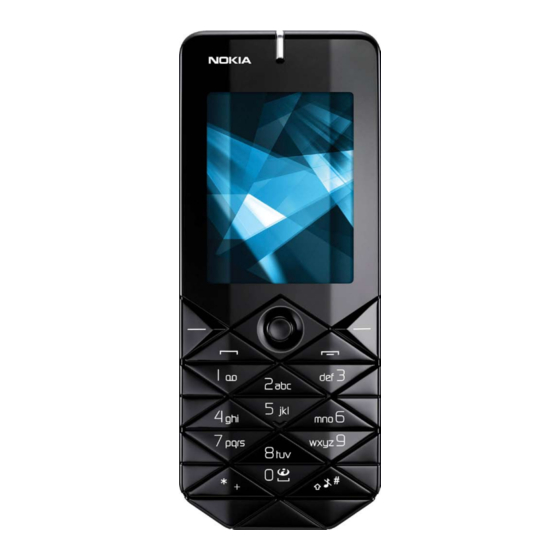
Nokia 7500 Service Manual
Hide thumbs
Also See for 7500:
- User manual (90 pages) ,
- Manual (72 pages) ,
- Service schematics (10 pages)
Table of Contents
Advertisement
Quick Links
Page
1
(18)
SERVICE MANUAL
Level 1&2
RM-249
CONFIDENTIAL
Copyright © 2007 NOKIA. All rights reserved.
RM-250
Transceiver characteristics:
Band:
RM-249: GSM: Tri-band 900/1800/1900MHz
RM-250: GSM: Tri-band 850/1800/1900MHz
WCDMA: ------
Display:
LCD: 5.08cm QVGA (2.0") (320x240 pixel); 16M colors
Camera:
Camera: 2.0 Megapixel SMIA85, 8x digital zoom
Operating System:
Series 40
Connections:
Wireless: Bluetooth
Connector: Mini USB Connector; AV Connector
Memory:
MicroSD™ (max 2GB)
Transceiver with BL-4B Li-Ion battery pack
Talk time
up to 2.8h
7500 RM-249 / RM250
Service Manual Level 1&2
Standby
Note
Depends on network
up to 10.4days
parameters
ISSUE 2
Advertisement
Table of Contents

Related Manuals for Nokia 7500


Summary of Contents for Nokia 7500
- Page 1 Connector: Mini USB Connector; AV Connector Memory: MicroSD™ (max 2GB) Transceiver with BL-4B Li-Ion battery pack Talk time Standby Note Depends on network up to 2.8h up to 10.4days parameters Page (18) ISSUE 2 CONFIDENTIAL Copyright © 2007 NOKIA. All rights reserved.
-
Page 2: Table Of Contents
CHANGE HISTORY COPYRIGHT WARNINGS AND CAUTIONS ESD PROTECTION CARE AND MAINTENANCE BATTERY INFORMATION EXPLODED VIEW SPARE PARTS OVERVIEW LEVEL 2 SOLDER COMPONENTS SERVICE TOOLS SW-UPDATE DISASSEMBLY INSTRUCTION ASSEMBLY HINTS Page (18) ISSUE 2 CONFIDENTIAL Copyright © 2007 NOKIA. All rights reserved. -
Page 3: Change History
Exploded view & Spare Parts overview updated The purpose of this document is to help NOKIA service levels 1 and 2 workshop technicians to carry out service to NOKIA products. This Service Manual is to be used only by authorized NOKIA service suppliers, and the content of it is confidential. -
Page 4: Warnings And Cautions
5. Ensure all cables and wires are repositioned correctly. ESD PROTECTION Nokia requires that service points have sufficient ESD protection (against static electricity) when servicing the phone. Any product of which the covers are removed must be handled with ESD protection. The SIM card can be replaced without ESD protection if the product is otherwise ready for use. -
Page 5: Care And Maintenance
Batteries’ performance is particularly limited in temperatures well below freezing. Do not dispose batteries in a fire! Dispose of batteries according to local regulations (e.g. recycling). Do not dispose as household waste. Page (18) ISSUE 2 CONFIDENTIAL Copyright © 2007 NOKIA. All rights reserved. -
Page 6: Exploded View
7500 RM-249 / RM250 Service Manual Level 1&2 EXPLODED VIEW See corresponding ITEM/CIRCUIT REF in the Spare Parts Service Bulletins on NOL. Page (18) ISSUE 2 CONFIDENTIAL Copyright © 2007 NOKIA. All rights reserved. -
Page 7: Spare Parts Overview
7500 RM-249 / RM250 Service Manual Level 1&2 SPARE PARTS OVERVIEW Page (18) ISSUE 2 CONFIDENTIAL Copyright © 2007 NOKIA. All rights reserved. -
Page 8: Level 2 Solder Components
7500 RM-249 / RM250 Service Manual Level 1&2 LEVEL 2 SOLDER COMPONENTS Page (18) ISSUE 2 CONFIDENTIAL Copyright © 2007 NOKIA. All rights reserved. -
Page 9: Service Tools
Service Bulletin (SB-011) on NOKIA On- line. Supplier or manufacturer contacts for tool re-order can be found in “Recom- mended service equipment” docu- ment on NOKIA Online. Page (18) ISSUE 2 CONFIDENTIAL Copyright © 2007 NOKIA. All rights reserved. - Page 10 To use FLS-5 Flash Dongle you have to follow the user guide inside the sales package. Please check always for the latest version of flash software, which is available on NOKIA Online. Page (18) ISSUE 2 CONFIDENTIAL Copyright © 2007 NOKIA. All rights reserved.
- Page 11 Service Manual Level 1&2 DISASSEMBLY INSTRUCTION 1. Nokia 7500 Disassembly. 2. You will need the Nokia Standard Toolkit version 2 as well as the camera removal tool SS-45. Also refer to the General Mechanical Guideline Video for additional hints about the tools and component handling.
- Page 12 Place a flat bladed screwdriver between the clip of the A- COVER ASSY and the B-COVER and bend them gently back. 11. Open the clips starting at the shown side. 12. Continue at the opposite side. Page (18) ISSUE 2 CONFIDENTIAL Copyright © 2007 NOKIA. All rights reserved.
- Page 13 16. Undo the screws in the order shown and remove them. 17. Remove the ENGINE MODULE from the B-COVER ASSY. 18. Take special care to the contacts springs on the PWB. Do not bend them. Page (18) ISSUE 2 CONFIDENTIAL Copyright © 2007 NOKIA. All rights reserved.
- Page 14 21..and remove it from the ENGINE MODULE. 22. Turn the LCD AM as shown and very gently open the LCD connector. 23. Remove the CAMERA GASKET. 24. Unlock and remove the CAMERA MODULE. Page (18) ISSUE 2 CONFIDENTIAL Copyright © 2007 NOKIA. All rights reserved.
- Page 15 28. Gently remove the ANTENNA from the B-COVER ASSY. 29. Carefully remove the FLASH PWB ASSY. 30. The CHARGER CONNECTOR and the MICROPHONE can be removed easily. The disassembly procedure is now finished. Page (18) ISSUE 2 CONFIDENTIAL Copyright © 2007 NOKIA. All rights reserved.
- Page 16 4. Ensure that the ANTENNA is fitted correctly. Avoid bending the spring contacts. 5. Insert the CAMERA MODULE paying attention to the correct 6. Fit the CAMERA GASKET to the CAMERA MODULE. position. Page (18) ISSUE 2 CONFIDENTIAL Copyright © 2007 NOKIA. All rights reserved.
- Page 17 11. Tighten the four screws to the torque of 21Ncm in the 12. Insert the two new screws and tighten them to the torque of order shown. 21Ncm in the order shown. Page (18) ISSUE 2 CONFIDENTIAL Copyright © 2007 NOKIA. All rights reserved.
- Page 18 13. Fit the BACK TRIM and check its correct position. 14. Squeeze the A-COVER a bit and gently fit the KEYPAD. Secure it by pressing it into the A-COVER. Page (18) ISSUE 2 CONFIDENTIAL Copyright © 2007 NOKIA. All rights reserved.