Table of Contents
Advertisement
Quick Links
www.nordictrack.com
Model No. NTEX05012.0
Serial No.
Write the serial number in the
space above for reference.
Serial Number Decal
(under frame)
QUESTIONS?
If you have questions, or if parts
are damaged or missing, DO NOT
CONTACT THE STORE; please
contact Customer Care.
IMPORTANT: Please register this
product (see the limited warranty
on the back cover of this manual)
before contacting Customer Care.
CALL TOLL-FREE:
1-800-TO-BE-FIT
(1-800-862-3348)
Mon.–Fri. 6 a.m.–6 p.m. MT
Sat. 8 a.m.–4 p.m. MT
ON THE WEB:
www.nordictrackservice.com
CAUTION
Read all precautions and instruc-
tions in this manual before using
this equipment. Keep this manual
for future reference.
USER'S MANUAL
Advertisement
Table of Contents

Summary of Contents for NordicTrack GX 4.2 Pro
- Page 1 Model No. NTEX05012.0 Serial No. USER’S MANUAL Write the serial number in the space above for reference. Serial Number Decal (under frame) QUESTIONS? If you have questions, or if parts are damaged or missing, DO NOT CONTACT THE STORE; please contact Customer Care.
-
Page 2: Table Of Contents
If a decal is missing or illegible, see the front cover of this manual and request a free replacement decal. Apply the decal in the location shown. Note: The decal(s) may not be shown at actual size. NORDICTRACK is a registered trademark of ICON IP, Inc. -
Page 3: Important Precautions
IMPORTANT PRECAUTIONS WARNING: To reduce the risk of serious injury, read all important precautions and instructions in this manual and all warnings on your exercise bike before using your exercise bike. ICON assumes no responsibility for personal injury or property damage sustained by or through the use of this product. -
Page 4: Before You Begin
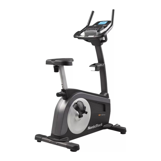
The GX 4.2 PRO exercise bike decal are shown on the front cover of this manual. provides an impressive selection of features designed... -
Page 5: Part Identification Chart
PART IDENTIFICATION CHART Use the drawings below to identify the small parts needed for assembly. The number in parentheses below each drawing is the key number of the part, from the PART LIST near the end of this manual. The number following the key number is the quantity needed for assembly. -
Page 6: Assembly
• To watch an assembly • To identify small parts, see page 5. video, go to http://productvideo.co/ • In addition to the included tool(s), assembly assembly/nordictrack or requires the following tools: use your mobile phone one Phillips screwdriver or smartphone to read the QR code at the right. - Page 7 3. Orient the Upright (4) and the Shield Cover (7) as shown. Slide the Shield Cover upward onto the Upright. Have a second person hold the Upright (4) and the Shield Cover (7) near the front of the Frame (1). Locate the wire tie inside the Upright (4).
- Page 8 5. Orient the Seat Post (6) as shown, and insert it into the Frame (1). Next, slide the Seat Post Sleeve (28) downward and press it into the Frame (1). Then, slide the Shield Cover (7) downward and press it onto the Right and Left Shields (10, 11). 10, 11 6.
- Page 9 7. Orient the Seat (23) and the Seat Carriage (24) as shown. Attach the Seat (23) to the Seat Carriage (24) with four M8 Locknuts (43), four M8 Split Washers (70), and four M8 Washers (64). Note: The Locknuts, Split Washers, and Washers may be preattached to the Seat.
- Page 10 10. Tip: Avoid pinching the wires. Attach the Console (13) to the Upright (4) with four M4 x 16mm Screws (34). Avoid pinching the wires 11. Have a second person hold the Handlebar (5) near the Upright (4). Connect the Pulse Wire (61) to the indicated wire on the Console (13).
- Page 11 12. Note: For clarity, the Console is not shown in this step. Attach the Front Console Cover (12) to the Handlebar (5) with two M4 x 16mm Screws (34). 13. Note: For clarity, the Console is not shown in this step. Hold the Rear Console Cover (15) near the Avoid pinching Upright (4).
- Page 12 15. Identify the Right Pedal (21). Using an adjustable wrench, firmly tighten the Right Pedal (21) clockwise into the Right Crank Arm (19). Tighten the Left Pedal (not shown) counter- clockwise into the Left Crank Arm (not shown). Strap Adjust the strap on the Right Pedal (21) by pull- ing downward on the end of the strap.
-
Page 13: The Chest Heart Rate Monitor
THE CHEST HEART RATE MONITOR HOW TO PUT ON THE HEART RATE MONITOR • Do not expose the heart rate monitor to direct sun- light for extended periods of time; do not expose it to The heart rate temperatures above 122° F (50° C) or below 14° F monitor consists of (-10°... -
Page 14: Exercise Bike Operation
EXERCISE BIKE OPERATION HOW TO PLUG IN THE POWER ADAPTER HOW TO ADJUST THE LATERAL POSITION OF THE SEAT IMPORTANT: If the exercise bike has been exposed to cold temperatures, allow it to warm to room To adjust the lateral temperature before plugging in the power adapter. - Page 15 CONSOLE DIAGRAM FEATURES OF THE CONSOLE The advanced console offers an array of features designed to make your workouts more effective and enjoyable. When you use the manual mode of the console, you can change the resistance of the pedals with the touch of a button.
- Page 16 HOW TO USE THE MANUAL MODE Distance (Dist.)—This display mode will show the distance that you have pedaled in miles or 1. Begin pedaling or press any button on the kilometers. console to turn on the console. Pulse—This display mode will show your heart rate When you turn on the console, the display will turn when you use the handgrip heart rate monitor or on.
- Page 17 Press the Home button to return to the default When your pulse is detected, a heart symbol will menu (see HOW TO CHANGE CONSOLE flash in the display each time your heart beats, SETTINGS on page 22 to set the default menu). one or two dashes will appear, and then your heart rate will be shown.
- Page 18 HOW TO USE AN ONBOARD WORKOUT As you exercise, you will be prompted to keep your pedaling speed near the target speed for the cur- 1. Begin pedaling or press any button on the rent segment. When an upward-pointing arrow console to turn on the console.
- Page 19 HOW TO USE A SET-A-GOAL WORKOUT Note: If you manually change the resistance during a calorie goal workout, the length of the workout 1. Begin pedaling or press any button on the will adjust automatically to ensure that you meet console to turn on the console.
- Page 20 HOW TO USE AN IFIT WORKOUT Press the Map button, the Train button, or the Lose Wt. button to download the next workout of that 1. Begin pedaling or press any button on the type in your schedule. console to turn on the console. Press the Compete button to compete in a race When you turn on the console, the display will turn that you have previously scheduled.
- Page 21 6. Follow your progress with the display. 8. Turn on the fan if desired. See step 4 on page 16. See step 6 on page 17. 9. When you are finished exercising, the console The My Trail tab will show a map of the trail you are walking or running or it will show a track and the will turn off automatically.
- Page 22 HOW TO CHANGE CONSOLE SETTINGS 6. Select an audio setting for the voice of the personal trainer if desired. The console features a user mode that allows you to view usage information, select a unit of measurement, Press the decrease button to view the audio setting and adjust the contrast level of the display.
-
Page 23: Fcc Information
FCC INFORMATION This equipment has been tested and found to comply with the limits for a Class B digital device, pursuant to part 15 of the FCC Rules. These limits are designed to provide reasonable protection against harmful interference in a residential installation. This equipment generates, uses, and can radiate radio frequency energy and, if not installed and used in accordance with the instructions, may cause harmful interference to radio communications. -
Page 24: Maintenance And Troubleshooting
MAINTENANCE AND TROUBLESHOOTING Inspect and properly tighten all parts of the exercise Then, remove all of the Screws (not shown) from the bike regularly. The exercise bike can be cleaned with Right and Left Shields (10, 11). a soft, damp cloth. To prevent damage to the console, keep liquids away from the console and keep the con- Carefully pull the tops of the Shields (10, 11) apart, sole out of direct sunlight. -
Page 25: Exercise Guidelines
EXERCISE GUIDELINES Burning Fat—To burn fat effectively, you must exer- WARNING: cise at a low intensity level for a sustained period of Before beginning this time. During the first few minutes of exercise, your or any exercise program, consult your physi- body uses carbohydrate calories for energy. -
Page 26: Part List
PART LIST Model No. NTEX05012.0 R0912A Key No. Qty. Description Key No. Qty. Description Frame Handgrip Front Stabilizer Pulley Rear Stabilizer Crank Upright Crank Bearing Handlebar Snap Ring Seat Post Eddy Mechanism Shield Cover M8 Locknut Accessory Tray M8 x 10mm Bolt Knob Shield Idler Right Shield... -
Page 27: Exploded Drawing
EXPLODED DRAWING Model No. NTEX05012.0 R0912A 68 62... -
Page 28: Ordering Replacement Parts
ORDERING REPLACEMENT PARTS To order replacement parts, please see the front cover of this manual. To help us assist you, be prepared to provide the following information when contacting us: • the model number and serial number of the product (see the front cover of this manual) • the name of the product (see the front cover of this manual) • t he key number and description of the replacement part(s) (see the PART LIST and the EXPLODED DRAWING near the end of this manual) LIMITED WARRANTY IMPORTANT: You must register this product within 30 days of the purchase date to avoid added fees for service needed under warranty.