HP t505 Troubleshooting Manual
Flexible thin client
Hide thumbs
Also See for t505:
- Hardware reference manual (44 pages) ,
- Product end-of-life disassembly instructions (12 pages)
Table of Contents
Advertisement
Quick Links
Advertisement
Table of Contents
Troubleshooting

Related Manuals for HP t505


Summary of Contents for HP t505
- Page 1 Troubleshooting Guide HP t505 Flexible Thin Client...
- Page 2 Microsoft and Windows are trademarks of Microsoft Corporation in the U.S. and other countries. The only warranties for HP products and services are set forth in the express warranty statements accompanying such products and services. Nothing herein should be construed as constituting an additional warranty.
- Page 3 About This Book WARNING! Text set off in this manner indicates that failure to follow directions could result in bodily harm or loss of life. CAUTION: Text set off in this manner indicates that failure to follow directions could result in damage to equipment or loss of information.
-
Page 4: Table Of Contents
Table of contents 1 Product Description ............................1 Product features ........................... 1 Serial Number Location ....................... 2 Front Panel Components ..................... 3 Rear Panel Components ..................... 4 Installing the Rubber Feet ....................4 Installing the Stand ......................5 Removing the Stand ......................6 2 Hardware Changes ............................ - Page 5 4 Diagnostics and Troubleshooting ....................... 26 LEDs ..............................26 Power-On Sequence .......................... 27 Power-On Diagnostic Tests ........................ 27 Beep Codes ............................28 POST Error Messages ........................28 Troubleshooting ..........................29 Basic Troubleshooting ....................... 29 Diskless (No-Flash) Unit Troubleshooting ................. 30 Troubleshooting Flowcharts ....................
- Page 6 Installing Remote Installation Services (RIS PXE Server) ..............53 Authorizing Remote Installation Services (RIS PXE Server) .............. 53 Configuring Remote Installation Services ..................54 Set User Permissions on the Active Directory Server ................ 54 RIS Menu ............................55 Creating Network Bootable Disk to Map Drives ................. 55 For More Information ..........................
-
Page 7: Product Description
● 5-minute hardware setup time ● central deployment and management using HP Management Solutions The following features are specific to the t505 thin client: ● Intel Atom D525 single core processor ● Intel PCH NM10 chipset ●... -
Page 8: Serial Number Location
Serial Number Location Every thin client includes a unique serial number located as shown in the following illustration. Have this number available when contacting HP customer service for assistance. Figure 1-1 Serial number location Chapter 1 Product Description... -
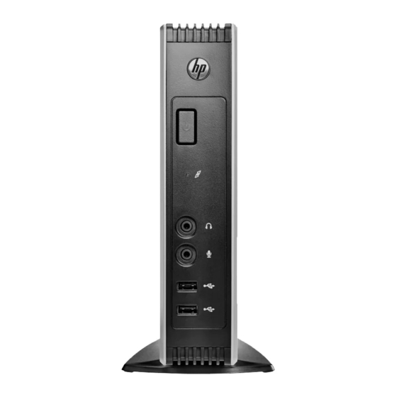
Page 9: Front Panel Components
Front Panel Components For more information, go to http://www.hp.com and search for your specific thin client model to find the model-specific QuickSpecs. Figure 1-2 Front panel components Power button Line-in (microphone) connector Flash activity LED Universal serial bus (USB) connectors (2) -
Page 10: Rear Panel Components
Rear Panel Components For more information, go to http://www.hp.com and search for your specific thin client model to find the model-specific QuickSpecs. Figure 1-3 Rear panel components Ethernet RJ-45 connector Cable lock slot Serial connectors (4) Power connector Parallel connector... -
Page 11: Installing The Stand
Align the feet with their holes and press them in securely. Figure 1-4 Installing the rubber feet Installing the Stand If you wish to use the thin client in a vertical orientation, you should install the stand for stability. To install the stand: Turn unit upside down. -
Page 12: Removing The Stand
Insert the tabs into the slots and slide the stand forward until it locks into place. Figure 1-5 Installing the stand Removing the Stand To remove the stand: Turn unit upside down. Press the tab (1), then slide the stand toward the rear of the thin client and lift it off the unit (2). Figure 1-6 Removing the stand Chapter 1 Product Description... -
Page 13: Hardware Changes
Hardware Changes General Hardware Installation Sequence To ensure the proper installation thin client hardware components: Back up any data, if necessary. If the thin client is powered on: Turn off the computer properly through the operating system, then turn off any external devices. -
Page 14: Removing And Replacing The Side Access Panel
Load any necessary drivers. NOTE: You can download select hardware drivers from HP. Go to http://www.hp.com search for your specific thin client model. Reconfigure the thin client, if necessary. Removing and Replacing the Side Access Panel Removing the Side Access Panel... -
Page 15: Replacing The Side Access Panel
Replacing the Side Access Panel To replace the access panel: Align the tabs on the access panel with the slots in the both sides of the chassis and place the access panel on the side of the unit, offset about 8.3 mm (1/3 inch) toward the top of the unit (1). Slide the panel toward the front of the unit until the panel is flush with the bottom panel of the chassis (2). -
Page 16: Installing Thin Client Options
Batteries, battery packs, and accumulators should not be disposed of together with the general household waste. In order to forward them to recycling or proper disposal, please use the public collection system or return them to HP, an authorized HP partner, or their agents. Chapter 2 Hardware Changes... -
Page 17: External Drives
For more information about available options, visit the HP website http://www.hp.com and search for your specific thin client model. -
Page 18: Configuring Powered Serial Ports
Configuring Powered Serial Ports Three configurable, powered serial ports, COM 2, COM 3, and COM 4, are standard on the thin client. COM 1 is a standard, non-powered serial port that cannot be configured. Some devices use a powered serial port. If the serial port is configured as a powered port, devices that support a powered serial interface do not require an external power source. - Page 19 Figure 2-4 Serial Port Jumper Locations on the System Board Item Jumper COM3 SP33 COM3 SP31 COM4 SP43 COM4 SP41 COM2 SP28 COM2 SP23 COM2 SP21 COM2 SP22 COM2 SP24 COM2 SP29 COM4 SP42 COM4 SP44 COM3 SP32 COM3 SP34 Before beginning the configuration process, review General Hardware Installation Sequence on page 7...
- Page 20 To configure the serial ports: Locate the serial port and jumper. Place jumpers on the appropriate pins. (See Table 2-3 Configuring Serial Port Power on page 15 to determine the appropriate pins.) CAUTION: An unsupported configuration can cause severe equipment damage. Carefully verify COM Port Jumper locations and supported configurations before you configure a serial port.
- Page 21 CAUTION: To prevent severe equipment damage, carefully verify the location of the COM Port Jumper before you configure it. See Figure 2-4 Serial Port Jumper Locations on the System Board on page 13 for locations. NOTE: The jumpers in the following table are in the same orientation illustrated in Figure 2-4 Serial Port Jumper Locations on the System Board on page Table 2-3...
- Page 22 Table 2-3 Configuring Serial Port Power (continued) Chapter 2 Hardware Changes...
- Page 23 Table 2-3 Configuring Serial Port Power (continued) Configuring Powered Serial Ports...
- Page 24 Table 2-3 Configuring Serial Port Power (continued) Chapter 2 Hardware Changes...
- Page 25 Table 2-3 Configuring Serial Port Power (continued) Configuring Powered Serial Ports...
- Page 26 Table 2-3 Configuring Serial Port Power (continued) Chapter 2 Hardware Changes...
-
Page 27: Bios Settings, (F10) Utility
BIOS Settings, (F10) Utility Using the BIOS Settings Changing BIOS Settings from the repset utility Some BIOS settings may be changed locally within the operating system without having to go through the F10 utility . This table identifies the items that can be controlled with this method. BIOS Setting Default Value Other Values... -
Page 28: Changing Bios Settings Using The F10 Utility
ECP Mode Use DMA DMA3 DMA1 USB Controller Enabled Disabled External USB Ports Enabled Disabled Halt On All, but Keyboard No Errors Security Option Setup Always USB Keyboard Support Enabled Disabled USB Mouse Support Disabled Enabled NOTE: Settings that can be controlled from the operating system with repset can also be controlled remotely by sending the client an Altiris job that uses the repset tool to apply the setting changes. -
Page 29: Setup Utility-System Information
Table 3-1 Setup (F10) Utility Main Menu (continued) Integrated Peripherals Setup Utility—Integrated Peripherals on page 24 Power Management Setup Setup Utility—Power Management Setup on page 25 Setup Utility—System Information NOTE: Support for specific Setup options may vary depending on the hardware configuration. Table 3-2 Setup Utility—System Information Option... -
Page 30: Setup Utility-Integrated Peripherals
Table 3-4 Setup Utility—Advanced BIOS Features (continued) 1st Boot Device Select Boot Device Priority. Default is USB. 2nd Boot Device Select Boot Device Priority. Default is ATA Flash. 3rd Boot Device Select Boot Device Priority. Default is Network. Boot Up Numlock Select power on state for Numlock. -
Page 31: Setup Utility-Power Management Setup
Setup Utility—Power Management Setup Table 3-6 Setup Utility—Power Management Setup Option Description PWRON After PWR- When power is lost and comes back, the option determines what power state the system should Fail go to. Options are Off, On, and Former-Sts. Default is Former-Sts. Wake on PME Enable/disable system wake-up capability for events received through the PCI bus. -
Page 32: Diagnostics And Troubleshooting
Diagnostics and Troubleshooting LEDs Table 4-1 Power and IDE Flash Activity LEDs Status Power LED Off When the unit is plugged into the wall socket and the Power LED is off, the unit is powered off. However, the network can trigger a Wake On LAN event in order to perform management functions. -
Page 33: Power-On Sequence
Power-On Sequence At power-on, the flash boot block code initializes the hardware to a known state, then performs basic power-on diagnostic tests to determine the integrity of the hardware. Initialization performs the following functions: Initializes CPU and memory controller. Initializes VGA software. Initializes and configures all PCI devices. -
Page 34: Beep Codes
BIOS code may have become corrupt. To restore a corrupt BIOS, refer to System BIOS on page 60 or call your local HP Call Center for a diagnosis. For phone numbers of an HP Call Center near you, visit the following Web site: http://www.hp.com/cgi-bin/hpsupport/index.pl CMOS battery failed The CMOS battery is no longer functional. -
Page 35: Troubleshooting
Troubleshooting Basic Troubleshooting If the thin client is experiencing operating problems or will not power on, review the following items. Table 4-4 Power-On Troubleshooting Issue Procedures The thin client unit is experiencing Ensure that the following connectors are securely plugged into the thin client operating problems. -
Page 36: Diskless (No-Flash) Unit Troubleshooting
Table 4-4 Power-On Troubleshooting (continued) A newly connected unknown USB An unknown USB peripheral may be connected and disconnected to a running peripheral does not respond or USB platform as long as you do not reboot the system. If problems occur, disconnect peripherals connected prior to the newly the unknown USB peripheral and reboot the platform. - Page 37 If you are running in a Linux environment go to step 3. If you are running in an MS RIS PXE environment press the key to activate the network service boot as soon as the DHCP IP information appears on the screen. If the unit does not boot to the network the server is not configured to PXE.
-
Page 38: Troubleshooting Flowcharts
Troubleshooting Flowcharts Initial Troubleshooting Start Intial Troubleshooting Go to Is there No Power power? Go to Is there No Video video? Go to Beeps, Error Messages LEDs, or error Go to Is the OS No OS Loading loading? Go to next page t5000 Troubleshooting Flow Chart Chapter 4 Diagnostics and Troubleshooting... -
Page 39: Initial Troubleshooting Part 2
Initial Troubleshooting Part 2 Continued from Initial Troubleshooting Go to Keyboard/ Non-functioning mouse pointing device or working? keyboard Go to No internal working? network connector Audio Go to No audio working? Windows desktop Go to displayed but No IP address can't connect? Boot in Go to... -
Page 40: No Power, Part 1
No Power, Part 1 Chapter 4 Diagnostics and Troubleshooting... -
Page 41: No Power, Part 2
No Power, Part 2 Troubleshooting... -
Page 42: No Power, Part 3
No Power, Part 3 Chapter 4 Diagnostics and Troubleshooting... -
Page 43: No Video, Part 1
No Video, Part 1 Troubleshooting... -
Page 44: No Video, Part 2
No Video, Part 2 Chapter 4 Diagnostics and Troubleshooting... -
Page 45: No Video, Part 3
No Video, Part 3 Troubleshooting... -
Page 46: No Video, Part 4
No Video, Part 4 Caution: Power is continuous to the system No Video Part 3 continued board and power supply even when the power No Video Part 4 switch is turned off. To prevent damage to the unit, disconnect the power cord from the power source or the unit before beginning Restart computer disassembly procedures. -
Page 47: Error Messages
Beep code - 1 Long, 3 Short. ROM failure. Create ROMPaq diskette and reload ROM. Download the ROMPaq from the HP Web site at: http://www.hp.com/products Notes: Short (S) and long (L) beeps will only be heard if the system has a speaker. LEDs will only function on PS/2 keyboards, not USB. -
Page 48: No Os Loading
NO OS Loading Chapter 4 Diagnostics and Troubleshooting... -
Page 49: Os Not Loading From Flash
OS Not Loading from Flash Troubleshooting... -
Page 50: Non-Functioning Pointing Device Or Keyboard
Non-Functioning Pointing Device or Keyboard Non-functioning Pointing Device or Keyboard Keyboard Pointing device or Done or mouse keyboard not operating working? properly. Reseat keyboard or Disconnect the non- mouse and disconnect functioning device other devices. and attach a known working keyboard/ mouse to the system. -
Page 51: No Internal Network Connection
Replace cable or or mouse have jack activated. working? Reimage using configured recovery process. in OS? Done Call your local HP Call Center for a diagnosis. To locate a local phone number, visit the HP Web site at: http://www.hp.com/cgi- bin/hpsupport/index.pl Troubleshooting... -
Page 52: No Audio
No Audio No Audio Is Volume Control or Media Player muted? If so, change the setting. Audio? Done Are speaker connectors in correct jacks? Try both audio jacks. Restore image using the Recovery process. Audio? Audio? Done In Control Panel's Sound and Audio, does the Audio tab Take the following actions: indicate whether the unit sees... -
Page 53: No Ip Address
No IP Address No IP Address Done Thin client have a valid IP address? Service the unit. Note: Refer to the Warranty for coverage information. Ping Done Loopback Thin client Reimage device have a valid using restore IP address? Ping Gateway Reboot unit and server. -
Page 54: Booting In Continuous Loop
Booting in Continuous Loop Chapter 4 Diagnostics and Troubleshooting... -
Page 55: Restoring The Flash Image
Unbundle the image to a directory for use in a custom deployment scenario or PXE image. Download and run the Package-for-the-Web deliverable (an .exe file) that contains the original factory image for the thin client. The HP Compaq Thin Client Imaging Tool (CRStart.exe) runs automatically. System Requirements... -
Page 56: Creating An Iso Image
Choose one of the deployment options: Each option is described in the following paragraphs. ● ISO Image ● USB Format ● Deployment During the restore process, the thin client flash drive will be reformatted and all data on it will be erased before the system image is copied to it. -
Page 57: Unpacking The Image And Tools For Deployment
Restart the thin client. When prompted Do you want to continue? [Y/N] click Y to begin the image restore process on the thin client. Unpacking the Image and Tools for Deployment Click Deployment. When prompted, select the destination directory for the imaging tools and image. The components that comprise DSKIMG.BIN are then unbundled. -
Page 58: Appendix A Adding An Image Restore Tool
Adding an Image Restore Tool Ensure that the boot order is set to use the Network as the first boot device. Ensure that IBR.exe (Image Restore) and Flash.dd are stored in the same directory on the server. (e.g., c:\program files\altiris\express\deployment server\images) From the Altiris Deployment Server Console, click File >... -
Page 59: Appendix B Configuring A Pxe Server
Configuring a PXE Server Prerequisites The services listed below must be running, and they may be running on different servers: ● Domain Name Service (DNS) ● Active Directory DHCP ● Remote Installation Services (RIS) on Microsoft Windows 2000 Server This documentation covers RIS setup, and assumes that servers 1, 2, and 3 (above) are already set up. -
Page 60: Configuring Remote Installation Services
Right-click DHCP (just above the domain name) and select Manage Authorized Servers. Click Authorize. Type the IP address of your RIS PXE server, and then click OK. Click OK. Log off from the DHCP Server. Configuring Remote Installation Services Use the default option to have RIS install on second hard drive (D:\ or E:\). Click Start >... -
Page 61: Ris Menu
Refer to the Microsoft Web site for instructions about creating a network bootable diskette. For More Information Thin client documentation (including white papers discussing software deployment methods): http://welcome.hp.com/country/us/en/support.html?pageDisplay=support. Type your model number into the for product box and navigate to the Manuals link. Altiris Deployment Solution Documentation: http://www.altiris.com/support/documentation/... -
Page 62: Appendix C Ftp Update
FTP Update HP FTP Image Update Client is a utility that allows image update from an FTP share to an HP thin client system running the WES operating system. For FTP Image Update to function properly, it requires the following available free space on the client: ●... -
Page 63: Description
Description The HP FTP Image Update Client can only be run by an administrator on an HP thin client system which has license to run XP Embedded operating system. Host Settings There are two ways to specify host settings: You can manually enter settings by clearing the Get Host Settings from DHCP server check box and filling in appropriate information to the Host ID, Path, User ID, and Password boxes. -
Page 64: Select Image To Update
A confirmation dialog similar to the following is displayed. Click No to abort the operation. If you click Yes, the HP FTP Image Update Client confirms that the flash drive has at least 200MB free to host the WinPE image. If the flash drive does not, the following error message is displayed. - Page 65 Select Image to Update...
-
Page 66: Appendix D System Bios
If the BIOS on the thin client is corrupt, the BIOS must be restored before the thin client will boot to the operating system. To update the system BIOS, download the Softpaq (for the product being updated) from the HP Web site. -
Page 67: Appendix E Electrostatic Discharge
Use conductive field service tools. ● Use a portable field service kit with a folding static-dissipating work mat. If you do not have any of the suggested equipment for proper grounding, contact an HP authorized dealer, reseller, or service provider. NOTE: For more information about static electricity, contact an HP authorized dealer, reseller, or service provider. -
Page 68: Appendix F Specifications
** The operating temperature range when the thin 1° C/300 m (1.8° F/1000 ft) to a maximum of 3 Km (10,000 client is attached to a flat panel using the HP Quick ft), with no direct, sustained sunlight. Upper limit may be Release is 50°... - Page 69 Table F-1 HP t505 Flexible Thin Client (continued) Power Supply 100–240 VAC 100–240 VAC Operating Voltage Range 50–60 Hz 50–60 Hz Rated Line Frequency Power Output (maximum) 65 W 65 W Rated Output Current (maximum) 3.42 A 3.42 A Output Voltage...
-
Page 70: Index
Index access panel electrostatic discharge 61 microphone connector location 3 removing 8 Ethernet connector location 4 mounting holes, VESA 4 replacing 9 adding an image restore tool 52 features 1 operating systems 1 altitude specifications 62 feet, installing 4 options authorizing Remote Installation Flash activity LED location 3 installing 7... - Page 71 relative humidity specifications temperature specifications 62 removing troubleshooting 29 battery 10 side access panel 8 updating a BIOS 60 stand 6 USB drive options 11 replacing USB ports battery 10 location 3, 4 side access panel 9 restore 52 restoring a corrupt BIOS 60 vertical orientation 5 restoring the flash image 49 VESA mounting holes 4...