Table of Contents
Advertisement
Advertisement
Table of Contents

Related Manuals for Denso J2534

Summary of Contents for Denso J2534
- Page 1 J2534 device DN-DST-010 Hardware Manual 1/36...
-
Page 2: Table Of Contents
Table of Contents 6. Description of the main unit 1. Preface 6-1. Names of the parts Trademarks 6-2. Indicator 2. Product overview 6-3. Strap hole About this product The countries where you can use 7. Connection this product 7-1. Connecting to the vehicle Disposal of the product 7-2. - Page 3 Table of Contents 8. Use cases 8-1. Before starting diagnosis 8-2. After diagnosis 9. Warranty and disclaimer 9-1. Warranty 9-2. Disclaimer Updated: Dec. 23, 2020 3/36...
-
Page 4: Preface
1. Preface Thank you for purchasing this product. Before using this product, read this document carefully so that you can use this product correctly and safely. This document explains handling of this product. Trademarks - SD Memory Card and SDHC Memory Card are the registered trademarks of Panasonic Corporation, SanDisk Corporation in the United State and Toshiba Corporation. -
Page 5: Product Overview
2. Product overview About this product This product is a compact and lightweight communication interface for diagnosis. With this product, diagnosis can be performed by connecting to a PC with the diagnostic software installed. This product alone cannot perform diagnosis. This is a compact product. -
Page 6: Disposal Requirements
2. Product overview Disposal requirements The product shall be disposed in accordance with all applicable legislation for disposal of Electrical and Electronic Equipment in each country and region. (e.g. WEEE Directive in EU) Please contact our authorized distributor or our sales agent when disposing it. Updated: Dec. -
Page 7: Product Specifications
2. Product overview Product specifications Specifications Item MATSU TAKE 32-bit microcomputer USB2.0 x 1 (Mini-DIN connector) Wireless LAN IEEE802.11abgn communication Bluetooth IEEE802.15.1 Ver.4.0/Class1 SD memory card Slot x 1 (supporting SD and SDHC memory cards) External interface *1 〇 〇 〇... -
Page 8: Safety Precautions
3. Safety precautions This section provides important information to use the product safely. Please read the section carefully and understand the following content (indications and symbols). Indication Description Indicates an item for which incorrect handling can result in a major WARNING accident involving death or serious injury. - Page 9 3. Safety precautions WARNING <WARNING for handling this product> ● Do not disassemble or alter this product. Doing so could result an overheating, fire, explosion, and/or electric shock. ● When using wireless communication with wireless models, do not use this product inside medical facilities or near medical devices.
- Page 10 3. Safety precautions CAUTION ● Inspect for foreign materials or damaged pins on each connector of this product before connecting to the diagnosis connector of the vehicle side. They may cause damage to the diagnosis connector on the vehicle side and the product’s connector terminal. ●...
- Page 11 3. Safety precautions CAUTION ● When using the wireless communication, do not use this product near an automatic control device such as an automatic door or a fire alarm. The radio waves could affect operation and result in an accident caused by malfunction. ●...
-
Page 12: Usage Precautions
4. Usage precautions This section contains precautions for using this product. CAUTION <Cautions on this product> ● Do not connect this product to anything with a voltage exceeding the ratings of this product. Doing so may cause a malfunction of the product. ●... - Page 13 4. Usage precautions CAUTION ● Do not drop this product or subject it to a strong impact. It may cause damages or malfunctioning of the product. ● Do not lift or drag this product by holding the USB cable connected to this product. If this product falls when the USB cable is disconnected, it could result in damages or malfunctioning of the product.
- Page 14 4. Usage precautions CAUTION <Caution on connecting to a PC> ● When connecting this product and a PC with the USB cable, always use a USB port on the PC capable to supply 500 mA or more current source. Insufficient current source supply could result in malfunction. ●...
-
Page 15: Product Configuration
5. Product configuration Main unit and accessories Check that you have all of the following components before using this product. Kit part number: 95171-01340 ( with wireless communication, Ethernet supported) 〃-01370 (with wireless communication supported) 〃-01390 ( without wireless communication supported, exclusive for USB communication) Part name Illustration Part No. -
Page 16: Description Of The Main Unit
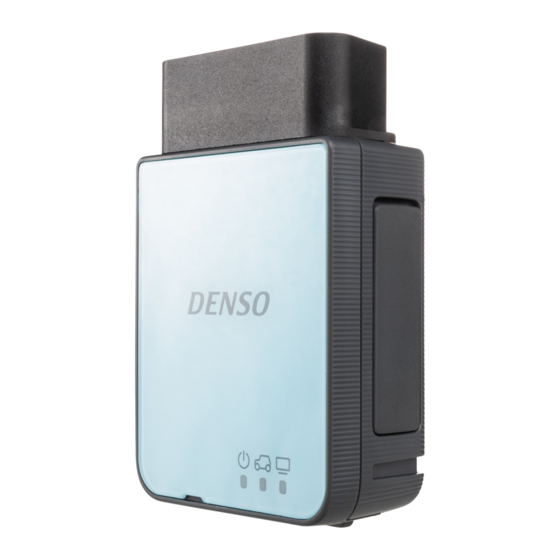
6-1. Names of the parts The names of the main unit parts are as follows: Connector jack (diagnosis connector on the vehicle side) Overall Plate [SD memory card access] indicator (only the model with an SD memory card slot) [Power] indicator Rubber cap [Vehicle] indicator Rubber cap... -
Page 17: Indicator
6-2. Indicator The indicators indicate the status of main unit. Refer to the setup manual for the LED lighting patterns. [Power] indicator [PC communication] indicator [SD memory card access] indicator (only the model with an SD memory card slot) [Vehicle] indicator T03025J Updated: Dec. -
Page 18: Strap Hole
6-3. Strap hole The strap hole can be used to attach a strap that serves as a reminder to help the user taking off the product after use. A strap is not supplied with this product. It must be purchased separately. An illustration showing the product with a strap attached. -
Page 19: Connection
7-1. Connecting to the vehicle Connect the main unit directly to the diagnosis connector on the vehicle side. After connecting, the main unit will power turn ON if power is supplied from the vehicle. Check the position of the diagnosis connector of the vehicle side in the repair manual of the vehicle. - Page 20 7-1. Connecting to the vehicle [CAUTION] - When connecting the main unit to the diagnosis connector on the vehicle side, always unlock the connector lock. If this product is connected to the diagnosis connector on the vehicle side when the connector lock is locked, it may damage the diagnosis connector on the vehicle side or this product.
-
Page 21: Connecting To The Pc
7-2. Connecting to the PC Wireless communication (Wireless model only) Refer to the setup manual for the connecting to the PC. [CAUTION] - When performing tasks that can cause vehicle malfunction if the wireless communication is disconnected, use the USB communication to connect with the PC by using the USB cable and the USB cable lock. - Page 22 7-2. Connecting to the PC - Use the USB cable for more data critical situation rather than wireless communication due to the greater possibility of loss of connection during data upload or download of the data transmission. - This information does not guarantee the connection between all of commercially available wireless communication modules and information terminals equipped with wireless communication (e.g., PC and cellular phone).
-
Page 23: Wireless Communication Characteristics
7-2. Connecting to the PC Wireless communication characteristics The communication range depends on any obstacles (i.e., human bodies, metal, walls) between this product and the wireless connection device, and the condition of the radio wave. If there is an obstacle between this product and the wireless connection device, the communication distance is shorter. - Page 24 7-2. Connecting to the PC Wireless communication characteristics To resolve poor communications, perform the following steps. - Place this product as close to a wireless LAN device as possible. - Keep a Bluetooth equipped device away from this product as much as possible. - If communications do not improve, turn off any Bluetooth equipped devices nearby.
-
Page 25: Usb Communication
7-2. Connecting to the PC USB communication connect USB cable and USB cable lock are used to the main unit and the PC. [NOTE] First, connect the main unit and USB cable (main unit-side connector) using the USB cable lock. Pass the main unit-side connector of the USB cable through the USB cable lock. - Page 26 7-2. Connecting to the PC Open the rubber cap on the main unit, and connect the main unit-side connector of the USB cable. [NOTE] Make sure that the direction of the connector is correct. Side with an arrow mark on the main unit-side connector is the upper side. USB cable lock Side with an arrow mark is upper side...
- Page 27 7-2. Connecting to the PC Attach the USB cable lock by aligning it with the guide section of the main unit. [NOTE] Store the rubber cap for main unit USB connector in the USB cable lock. Press until you hear a click sound indicating it is locked. Check that the USB cable lock is securely fixed to the main unit.
- Page 28 7-2. Connecting to the PC Connect the PC side connector of the USB cable to the USB port of the PC. After connecting the main unit, power supply becomes ON. Connect the PC side connector to USB port. USB cable USB cable lock PC side connector T03028J...
- Page 29 7-2. Connecting to the PC Removing the USB cable lock [NOTE] USB cable lock must be removed before removing the USB cable. Press the lock release on both sides and remove it from the main unit. USB cable lock Lock Lock release...
-
Page 30: Use Cases
8. Use cases [CAUTION] - This product alone cannot perform diagnosis. A PC with diagnostic software installed is required. - Leaving the main unit connected in the vehicle could result in flat battery of the vehicle. - Driving while the main unit is connected to the vehicle may cause difficulty for proper driving operation. -
Page 31: Before Starting Diagnosis
8-1. Before starting diagnosis Ensure that the connector lock is released. Connector lock (lock released) Reference: Page 19 Connecting to the vehicle (Chapter 7 Connection) T03030J Connected to vehicle side Connect the main unit to the diagnosis connector on the diagnosis connector. - Page 32 8-1. Before starting diagnosis Turn ON the starter switch (ignition switch) or start the engine of the vehicle. [NOTE] This product cannot communicate with the system on the vehicle when the starter switch (ignition switch) of the vehicle is OFF or set to ACC. Launch the diagnostic software and start diagnosis.
-
Page 33: After Diagnosis
8-2. After diagnosis Exit the diagnostic software. Turn the vehicle starter switch (ignition switch) OFF. Ensure that the connector lock is released. Connector lock (lock released) T03030J [CAUTION] If the main unit is disconnected from the diagnosis connector on the vehicle side while the connector lock is locked, it may damage the diagnosis connector on the vehicle side and/or the main unit connector. - Page 34 8-2. After diagnosis from Disconnect the main unit the diagnosis connector on the vehicle side. [CAUTION] Do not forget to disconnect the main unit. Leaving the main unit connected in the vehicle could result in flat battery of the vehicle. In addition, driving while the main unit is connected to the vehicle, may cause difficulty for proper driving operation.
-
Page 35: Warranty
9-1. Warranty The warranty period of this set is one year after the purchase day. However accessories are not covered, main unit only. Free repair warranty is applied only for the failure under proper operation conditions within the warranty period. Non-free repair is applied to the following cases even if the valid warranty period remains. -
Page 36: Disclaimer
9-2. Disclaimer - We shall have no liability for any information leaked during the wireless communication. By exchanging information using the radio wave, the wireless communication allows free wireless connections in a range to which the radio wave reaches. On the other hand, an insufficient security setting may allow unauthorized access by a third- party person with a bad intention.