
Related Manuals for Viper AS4335C


Summary of Contents for Viper AS4335C
- Page 1 AS4335C INSTRUCTION FOR USE Model No.: 50000584 VS15352 Rev. A JAN. 2020 Original instructions...
- Page 2 TABLE OF CONTENTS 1-20 ENGLISH INSTRUCTION FOR USE……………………………………… FRANÇAIS MANUEL UTILISATEUR……………………………………… 21-40 41-60 ESPAÑOL INSTRUCCIONES DE USO……………………………………. ……………………………………………………………………… 61-82 PARTS LIST...
-
Page 3: Table Of Contents
INSTRUCTION FOR USE ENGLISH TABLE OF CONTENTS INTRODUCTION ............................2 GUIDE PURPOSE AND CONTENTS .......................... 2 HOW TO KEEP THIS INSTRUCTION FOR USE ....................... 2 DECLARATION OF CONFORMITY ........................... 2 ACCESSORIES AND MAINTENANCE ........................2 CHANGE AND IMPROVEMENT ..........................2 SCOPE OF APPLICATION ............................2 MACHINE IDENTIFICATION DATA ......................... -
Page 4: Introduction
INSTRUCTION FOR USE ENGLISH INTRODUCTION NOTE The numbers in brackets refer to the components shown in Machine Description chapter. GUIDE PURPOSE AND CONTENTS The purpose of this instruction for use is to provide the operator with all basic information and technical characteristics, operation, machine inactivity, spare parts and safety conditions etc. -
Page 5: Transport And Unpacking
INSTRUCTION FOR USE ENGLISH TRANSPORT AND UNPACKING When the carrier delivers the machine, make sure the packaging and machine are both whole and undamaged. If there is any damage, inform the carrier before accepting the goods, and reserve the right to compensation for the damage. Follow the instructions on packaging strictly when unpacking the machine. -
Page 6: General Safety Instruction
INSTRUCTION FOR USE ENGLISH GENERAL SAFETY INSTRUCTION Specific warnings and cautions to inform about potential damages to people and machine are shown below. DANGER! This machine must be operated by trained and authorized personnel according to guidance of the manual. ... - Page 7 INSTRUCTION FOR USE ENGLISH To ensure machine proper and safe operation, the scheduled maintenance shown in the relevant chapter of this Manual, must be performed by the authorized personnel or an authorized Service Center. The machine must be properly disposed of, due to the presence of toxic-harmful materials, which are subject to standards that require disposal in special centers (see Scrapping chapter).
-
Page 8: Machine Description
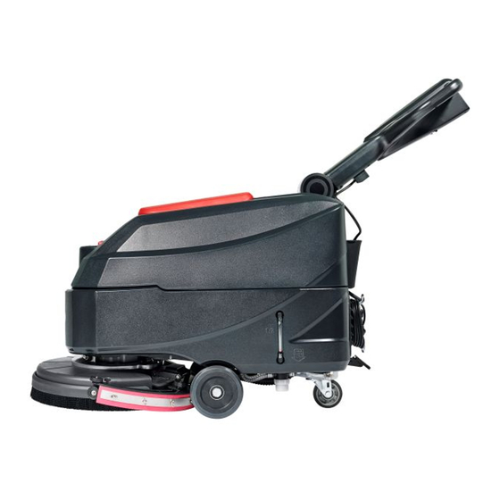
INSTRUCTION FOR USE ENGLISH MACHINE DESCRIPTION MACHINE STRUCTURE (as shown in Figure 1) Handlebar 22. Solution filter Safety switch lever 23. Front wheels Handlebar adjusting lever 24. Squeegee assembly Recovery water drain hose 25. Pad-holder Recovery tank lid 26. Control panel Fresh water cover 27. -
Page 9: Control Panel (As Shown In Figure 2)
INSTRUCTION FOR USE ENGLISH CONTROL PANEL (as shown in Figure 2) Power switch Solution switch Vacuum switch Figure 2 Figure 2 MACHINE SIZE 33 Inches (835 mm) 22.5 Inches (570 mm) 40.2 Inches (1020 mm) -
Page 10: Technical Parameters
INSTRUCTION FOR USE ENGLISH TECHNICAL PARAMETERS Model Parameter Type Units AS4335C-US Solution tank capacity L / Gal 35 L / 9.25 Gal. Recovery tank capacity L / Gal 35 L / 9.25 Gal. Machine Length mm/Inches 933 mm / 36.7 Inches... -
Page 11: Wiring Diagram (120Vac)
INSTRUCTION FOR USE ENGLISH WIRING DIAGRAM (110-120VAC) -
Page 12: Operating Guide
INSTRUCTION FOR USE ENGLISH OPERATING GUIDE WARNING! On some points of the machine there are some adhesive plates indicating: – DANGER! – WARNING! – CAUTION! – CONSULTATION While reading this Manual, the operator must pay particular attention to the symbols shown on the plates. Do not cover these plates for any reason and immediately replace them if damaged. -
Page 13: Squeegee Assemble Installation And Removal
INSTRUCTION FOR USE ENGLISH SQUEEGEE ASSEMBLE INSTALLATION AND REMOVAL CAUTION! It is advisable to wear protective gloves when installation and removal the squeegee assemble because there may be sharp debris. Push the machine to a level floor. Ensure that the machine is off. Lower the brush/pad-holder deck (12, Figure 1) by lifting the pedal (36), Brush on the floor. -
Page 14: Solution Or Washing Water Tank Filling
INSTRUCTION FOR USE ENGLISH SOLUTION OR WASHING WATER TANK FILLING Open the water inlet cover (A, Figure 5). Fill with water or solution suitable for work performance. The solution temperature must not exceed +104F (+40°C). Do not overfill the tank, refer to water level indicator (B, Figure 5) for the water volume. -
Page 15: Machine Operation (Scrubbing And Drying)
INSTRUCTION FOR USE ENGLISH Figure 7 Figure 7 NOTE To move the machine forward, press either the left or right safety switch lever (E, Figure 7) or both. If necessary, press the handlebar adjusting lever (3, Figure 1) to adjusting the handlebar height. If necessary, trun off the machine, and adjust the solution flow with the ball valve handle. -
Page 16: Tank Emptying
INSTRUCTION FOR USE ENGLISH NOTE For correct scrubbing/drying of floors at the sides of the walls, it is Suggested to go near the walls with the right side of the machine (A and B, Figure 8) as shown in the figure. Figure 8 Figure 8 CAUTION! -
Page 17: After Using The Machine
INSTRUCTION FOR USE ENGLISH Recovery water tank emptying Stop the machine. Lift the brush/pad-holder deck (I, Figure 7) and the squeegee (H) by pressing the pedal (G). Push the machine to the appointed disposal area. Empty the recovery water tank with the hose (F, Figure 7). Then, rinse the recovery tank (C, Figure 9) with clean water. -
Page 18: Scheduled Maintenance Table
INSTRUCTION FOR USE ENGLISH SCHEDULED MAINTENANCE TABLE CAUTION! The procedure marked with (1) must be performed when the machine is used after 9 hours for the first time. The procedure marked with (2) must be done by Service Center that is qualified by our company. Procedure Daily, after each use Weekly... -
Page 19: Squeegee Cleaning
INSTRUCTION FOR USE ENGLISH SQUEEGEE CLEANING NOTE The squeegee must be clean and its blades must be in good conditions in order to get a good drying. CAUTION! It is advisable to wear protective gloves when cleaning the squeegee because there may be sharp debris. Push the machine to a level floor. -
Page 20: Squeegee Blade Check And Replacement
INSTRUCTION FOR USE ENGLISH SQUEEGEE BLADE CHECK AND REPLACEMENT Clean the steel or the plastic squeegee, as shown in the previous paragraph. Check that the edges (E, Figure 13) of the front blade (A) and the edges (F) of the rear blade (C) lay down on the same level, along their length; if necessary adjust their height according to the following procedure: ... -
Page 21: Accessories/Options
INSTRUCTION FOR USE ENGLISH Figure 14 Figure 14 ACCESSORIES/OPTIONS In addition to the standard components, the machine can be equipped with the following accessories/options, according to the machine specific use: For further information concerning the above-mentioned optional accessories, contact an authorized Retailer. ACCESSORIES/OPTIONS See “Parts List”... -
Page 22: Troubleshooting
Plastic hose and plastic parts. Electrical and electronic components. (*) – Please contact our company service center destroying any electrical and electronic components. Machine material composition and recyclability Recyclable percent- AS4335C Type weight percentage% Aluminium 100% Electric motors-various Ferrous materials... - Page 23 INSTRUCTIONS D’UTILISATION FRANÇAIS TABLE DES MATIÈRES INTRODUCTION ............................22 BUT ET CONTENU DU GUIDE ..........................22 COMMENT CONSERVER CES INSTRUCTIONS D'UTILISATION ............... 22 DÉCLARATION DE CONFORMITÉ .......................... 22 ACCESSOIRES ET ENTRETIEN ..........................22 CHANGEMENT ET AMÉLIORATION ........................22 CHAMP D'APPLICATION ............................22 DONNÉES D'IDENTIFICATION DE LA MACHINE ....................
-
Page 24: Introduction
INSTRUCTIONS D’UTILISATION FRANÇAIS INTRODUCTION REMARQUE Les chiffres entre parenthèses renvoient aux éléments présentés dans le chapitre Description de la Machine. BUT ET CONTENU DU GUIDE Le but de ces instructions d'utilisation est de fournir à l’opérateur toutes les informations de base et les caractéristiques techniques, les conditions de fonctionnement, d'inactivité, les pièces détachées et les conditions de sécurité... -
Page 25: Transport Et Déballage
INSTRUCTIONS D’UTILISATION FRANÇAIS TRANSPORT ET DÉBALLAGE Lorsque le transporteur livre la machine, s'assurer que l'emballage et la machine sont à la fois intacts et en bon état. En cas de dommages, en informer le transporteur avant d'accepter les marchandises et réservez-vous le droit à compensation pour les dommages. Suivre attentivement les instructions sur l'emballage, lors du déballage de la machine. -
Page 26: Consignes Générales De Sécurité
INSTRUCTIONS D’UTILISATION FRANÇAIS CONSIGNES GÉNÉRALES DE SÉCURITÉ Les avertissements et les mises en garde spécifiques, pour informer des dommages potentiels aux personnes et à la machine, sont indiqués ci-dessous. DANGER ! Cette machine doit être exploitée par du personnel qualifié et autorisé selon les conseils du manuel. ... - Page 27 INSTRUCTIONS D’UTILISATION FRANÇAIS Pour assurer un fonctionnement adéquat et sécurisé de la machine, l'entretien prévu indiqué dans le chapitre respectif de ce manuel, doit être effectué par le personnel autorisé ou un centre d'entretien agréé. La machine doit être correctement jetée, étant donné la présence de matières toxiques soumises à des normes qui exigent l'élimination dans des centres spéciaux (voir le chapitre Mise au rebut).
-
Page 28: Description De La Machine
INSTRUCTIONS D’UTILISATION FRANÇAIS DESCRIPTION DE LA MACHINE STRUCTURE DE LA MACHINE (comme représenté sur la Figure 1) Poignée 22. Filtre de solution Levier d'interrupteur de sécurité 23. Roues avant Levier de réglage de guidon 24. Ensemble d'embouchure Tuyau de vidange de l'eau de récupération 25. -
Page 29: Panneau De Commande (Comme Représenté Sur La Figure 2)
INSTRUCTIONS D’UTILISATION FRANÇAIS PANNEAU DE COMMANDE (comme représenté sur la Figure 2) 39. Interrupteur électrique 40. Interrupteur de solution 41. Interrupteur d'aspiration Figure 2 Figure 2 DIMENSIONS DE LA MACHINE 33 Inches (835 mm) 22.5 Inches (570 mm) 40.2 Inches (1020 mm) -
Page 30: Caracteristiques Techniques
INSTRUCTIONS D’UTILISATION FRANÇAIS CARACTERISTIQUES TECHNIQUES Modèle Type de paramètre Unités AS4335C-US Capacité du réservoir de solution L / Gal 35 l / 9,25 Gal. Capacité du réservoir de récupération L / Gal 35 l / 9,25 Gal. Longueur de la machine... -
Page 31: Schéma De Câblage (120Vca)
INSTRUCTIONS D’UTILISATION FRANÇAIS SCHÉMA DE CÂBLAGE (110-120VAC) -
Page 32: Guide D'utilisation
INSTRUCTIONS D’UTILISATION FRANÇAIS GUIDE D'UTILISATION AVERTISSEMENT ! En certains endroits de la machine il y a des plaques adhésives indiquant : – DANGER ! – AVERTISSEMENT ! – ATTENTION ! – CONSULTATION En lisant ce manuel, l'opérateur doit prêter une attention particulière aux symboles figurant sur les plaques. Ne pas couvrir ces plaques pour une raison quelconque et les remplacer immédiatement en cas de détérioration. -
Page 33: Pose Et Dépose De L'ensemble Racloir
INSTRUCTIONS D’UTILISATION FRANÇAIS POSE ET DÉPOSE DE L'ENSEMBLE RACLOIR ATTENTION ! Il est conseillé de porter des gants de protection lors de l'installation et de la dépose du racloir car il peut y avoir des débris tranchants. Pousser la machine sur un sol plat. Vérifiez que la machine est arrêtée. -
Page 34: Remplissage Du Réservoir Avec Une Solution Ou De L'eau De Lavage
INSTRUCTIONS D’UTILISATION FRANÇAIS REMPLISSAGE DU RÉSERVOIR AVEC UNE SOLUTION OU DE L'EAU DE LA- VAGE Ouvrez le couvercle d'entrée d'eau (A, Figure 5). Remplir d'eau ou de solution adaptée au travail. La température de la solution ne doit pas dépas- ser +104 °F (+40 °C). -
Page 35: Fonctionnement De La Machine (Brossage Et Séchage)
INSTRUCTIONS D’UTILISATION FRANÇAIS Figure 7 Figure 7 REMARQUE Pour déplacer la machine vers l'avant, appuyez sur le levier du contacteur de sécurité gauche ou droit (C, schéma 7) ou les deux. Si nécessaire, appuyez sur le levier de réglage du guidon (3, Figure 1) pour régler sa hauteur. Si nécessaire, arrêtez la machine et réglez le débit de la solution à... -
Page 36: Vidange Du Réservoir
INSTRUCTIONS D’UTILISATION FRANÇAIS REMARQUE Pour un nettoyage/séchage correct des sols sur les côtés des murs, il est conseillé de le faire par le côté droit de la machine (A et B, Figure 8) comme illustré sur la figure. Figure 8 Figure 8 ATTENTION ! Pour éviter tout dommage à... -
Page 37: Après Utilisation De La Machine
INSTRUCTIONS D’UTILISATION FRANÇAIS Vider le réservoir d'eau récupération Arrêter la machine. Levez la tête de lavage (I, Figure 7) et la raclette (H) en appuyant sur la pédale (G). Poussez la machine jusqu'à la zone de rangement désignée. Videz le réservoir d'eau de récupération à l'aide du flexible (F, Figure 7). -
Page 38: Calendrier D'entretien Programme
INSTRUCTIONS D’UTILISATION FRANÇAIS CALENDRIER D'ENTRETIEN PROGRAMME ATTENTION ! La procédure, indiquée avec (1), doit être effectuée lorsque la machine est utilisée après 9 heures pour la première fois. La procédure indiquée par (2) doit être effectuée par le Centre de service qualifié par notre société. Quotidien, après Chaque Chaque... -
Page 39: Nettoyage De L'embouchure
INSTRUCTIONS D’UTILISATION FRANÇAIS NETTOYAGE DE L’EMBOUCHURE REMARQUE La raclette doit être propre et ses lames doivent être en bon état pour obtenir un bon séchage. ATTENTION ! Il est conseillé de porter des gants de protection lors du nettoyage de l'embouchure, car il peut y avoir des débris pointus. -
Page 40: Vérification Et Remplacement De La Lamelle De L'embouchure
INSTRUCTIONS D’UTILISATION FRANÇAIS VÉRIFICATION ET REMPLACEMENT DE LA LAMELLE DE L'EMBOUCHURE Nettoyez la raclette en acier ou en plastique, comme indiqué au paragraphe précédent. Vérifiez que les bords (E, Figure 13) de la lame avant (A) et les bords (F) de la lame arrière (C) sont bien au même niveau sur toute leur longueur ;... -
Page 41: Accessoires/Options
INSTRUCTIONS D’UTILISATION FRANÇAIS Figure 14 Figure 14 ACCESSOIRES/OPTIONS En plus des composants standards, la machine peut être équipée des accessoires/options suivants, selon l'utilisation spécifique de la machine : Pour de plus amples informations concernant les accessoires optionnels mentionnés ci-dessus, contacter un distributeur agréé. ACCESSOIRES/OPTIONS Voir la rubrique «... -
Page 42: Dépannage
INSTRUCTIONS D’UTILISATION FRANÇAIS DÉPANNAGE Problème Causes probables Solution Le câblage n'est pas branché correctement ou il est Vérifiez le câblage ou contactez le distribu- La machine ne fonctionne pas défectueux. teur. Balai en carbone usé. Contactez le distributeur. Le câblage n'est pas branché correctement ou il est Vérifiez le câblage ou contactez le distribu- Le moteur d'aspiration ne fonc- défectueux. - Page 43 INSTRUCCIONES DE USO ESPAÑOL ÍNDICE INTRODUCCIÓN ............................42 PROPÓSITO Y CONTENIDOS DE ESTA GUÍA ....................... 42 CÓMO GUARDAR EL MANUAL DE INSTRUCCIONES DE USO ................ 42 DECLARACIÓN DE CONFORMIDAD ........................42 ACCESORIOS Y MANTENIMIENTO ........................42 CAMBIOS Y MEJORAS .............................. 42 ÁMBITO DE APLICACIÓN ............................
-
Page 44: Introducción
INSTRUCCIONES DE USO ESPAÑOL INTRODUCCIÓN NOTA Los números entre paréntesis hacen referencia a los componentes que se muestran en la sección Descripción de la Máquina. PROPÓSITO Y CONTENIDOS DE ESTA GUÍA El propósito del presente Manual de Instrucciones de Uso es proporcionar al operador toda la información básica, los datos técnicos, el funcionamiento, el almacenamiento, las piezas de repuesto, las condiciones de seguridad etc. -
Page 45: Transporte Y Desembalaje
INSTRUCCIONES DE USO ESPAÑOL TRANSPORTE Y DESEMBALAJE Cuando el transportista entrega la máquina, asegúrese de que el embalaje y la máquina se encuentran enteros y sin daños. En caso de daños, avise al transportista dicha situación, antes de aceptar las mercancías para reservarse el derecho de indemnización. Al desembalar la máquina siga estrictamente las instrucciones en el embalaje. -
Page 46: Instrucciones Generales De Seguridad
INSTRUCCIONES DE USO ESPAÑOL INSTRUCCIONES GENERALES DE SEGURIDAD Advertencias y precauciones específicas para informar acerca de los posibles daños a las personas y a la máquina se muestran a continuación. ¡PELIGRO! Esta máquina debe ser operada por personal capacitado y autorizado de acuerdo con las instrucciones del manual. ... - Page 47 INSTRUCCIONES DE USO ESPAÑOL Para garantizar el funcionamiento correcto y seguro de la máquina, el mantenimiento programado que se muestra en el capítulo correspondiente de este manual, debe ser realizado por el personal autorizado o un Centro de asistencia autorizado.
-
Page 48: Descripción De La Máquina
INSTRUCCIONES DE USO ESPAÑOL DESCRIPCIÓN DE LA MÁQUINA CONSTRUCCIÓN DE LA MÁQUINA (como se indica en Figura 1) Manillar 22. Filtro de la solución detergente Palanca del interruptor de seguridad 23. Ruedas delanteras Palanca de ajuste del manillar 24. Grupo boquilla Tubo de descarga del agua de recuperación 25. -
Page 49: Panel De Control (Como Se Indica En La Figura 2)
INSTRUCCIONES DE USO ESPAÑOL PANEL DE CONTROL (como se indica en la Figura 2) 39. Interruptor de alimentación 40. Interruptor de la solución 41. Interruptor de aspiración Figure 2 Figura 2 DIMENSIONES DE LA MÁQUINA 33 Inches (835 mm) 22.5 Inches (570 mm) 40.2 Inches (1020 mm) -
Page 50: Parámetros Técnicos
INSTRUCCIONES DE USO ESPAÑOL PARÁMETROS TÉCNICOS Modelo Tipos de parámetros Unidades AS4335C-US Capacidad del depósito de la solución deter- L / Gal 35 L / 9,25 Gal. gente Capacidad del depósito de recuperación L / Gal 35 L / 9,25 Gal. -
Page 51: Esquema Eléctrico (120 Vca)
INSTRUCCIONES DE USO ESPAÑOL ESQUEMA ELÉCTRICO (110-120 VAC) -
Page 52: Guía De Funcionamiento
INSTRUCCIONES DE USO ESPAÑOL GUÍA DE FUNCIONAMIENTO ¡ADVERTENCIA! En algunos lugares de la máquina se encuentran algunas placas adhesivas que indican: - ¡PELIGRO! - ¡ADVERTENCIA! - ¡ATENCIÓN! - CONSULTA Durante la lectura de este manual, el operador debe prestar especial atención a los símbolos que aparecen en las placas. No cubra estas placas por cualquier motivo y reemplácelas inmediatamente si están dañadas. -
Page 53: Instalación Y Extracción De La Boquilla
INSTRUCCIONES DE USO ESPAÑOL INSTALACIÓN Y EXTRACCIÓN DE LA BOQUILLA ¡ATENCIÓN! Es aconsejable usar guantes de protección para instalar y quitar el grupo boquilla, dada la posible presencia de residuos cortantes. Empuje la máquina hacia una superficie nivelada. Asegúrese de que la máquina está apagada. Baje el cabezal del cepillo/porta-pad (12, Figura 1) levantando el pedal (36), cepillo en el suelo. -
Page 54: Llenar El Depósito De Solución Oagua De Lavado
INSTRUCCIONES DE USO ESPAÑOL LLENAR EL DEPÓSITO DE SOLUCIÓN O AGUA DE LAVADO Abra la tapa de entrada del agua (A, Figura 5). Llene con agua o con una solución apropiada para el trabajo que se tiene que realizar. La temperatura de la solución no debe superar los +104°F (40°C). -
Page 55: Conducción De La Máquina (Fregar Y Secar)
INSTRUCCIONES DE USO ESPAÑOL Figure 7 Figura 7 NOTA Para la marcha adelante, pulse la palanca del interruptor de seguridad (E, Figura 7) derecha o izquierda, o ambas. Si es necesario, presione la palanca de ajuste del manillar (3, Figura 1) para ajustar la altura del manillar. Si es necesario, apague la máquina y ajuste el flujo de solución con la manilla de la válvula de bola. -
Page 56: Vaciar Los Depósitos
INSTRUCCIONES DE USO ESPAÑOL NOTA Para el fregado/secado correcto de los suelos en los lados de las paredes, se sugiere aproximarse a las paredes con el lado derecho de la máquina (A y B, Figura 8) como se indica en la figura. Figure 8 Figura 8 ¡ATENCIÓN! -
Page 57: Después Del Uso De La Máquina
INSTRUCCIONES DE USO ESPAÑOL Vaciar el depósito de agua sucia Parar la máquina. Levante el cabezal del cepillo/porta-pad (I, Figura 7) y la boquilla (L) presionando el pedal (G). Empuje la máquina hacia el área de eliminación designada. Vacíe el depósito de recuperación con el tubo (F, Figura 7). Luego, enjuague el depósito de recogida (C, Figura 9) con agua limpia. -
Page 58: Tabla De Mantenimiento Programado
INSTRUCCIONES DE USO ESPAÑOL TABLA DE MANTENIMIENTO PROGRAMADO ¡ATENCIÓN! El procedimiento marcado con (1) debe realizarse 9 horas después del primer uso de la máquina. El procedimiento marcado con (2) debe ser realizado por el Centro de asistencia designado por nuestra empresa. Diario, después de cada Procedimiento Semanal... -
Page 59: Limpieza De La Boquilla
INSTRUCCIONES DE USO ESPAÑOL LIMPIEZA DE LA BOQUILLA NOTA La boquilla debe estar limpia igual que los labios deben estar en buenas condiciones para obtener un buen secado. ¡ATENCIÓN! Es aconsejable usar guantes de protección al limpiar la boquilla, ya que puede haber escombros cortantes. Empuje la máquina hacia una superficie nivelada. -
Page 60: Control Y Sustitución De Los Labios De La Boquilla
INSTRUCCIONES DE USO ESPAÑOL CONTROL Y SUSTITUCIÓN DE LOS LABIOS DE LA BOQUILLA Limpie la boquilla de acero o de plástico, tal y como se indica en el párrafo anterior. Compruebe si los bordes (E, Figura 13) del labio delantero (A) y los bordes (F) del labio trasero (C) están en el mismo nivel, a lo largo de su longitud;... -
Page 61: Accesorios/Opciones
INSTRUCCIONES DE USO ESPAÑOL Figure 14 Figura 14 ACCESORIOS/OPCIONES Además de los componentes instalados en la versión estándar, la máquina puede equiparse con los siguientes accesorios/opciones, según el uso específico: Para más información sobre los accesorios opcionales mencionados anteriormente, póngase en contacto con un Revendedor autorizado. ACCESORIOS/OPCIONES Consulte la sección «Catálogo de piezas de repuestos»... -
Page 62: Resolución De Problemas
Componentes eléctricos y electrónicos. (*) – Por favor contacte con el Centro de asistencias de nuestra Empresa para desechar cualquier componente electrónico y eléctrico. Composición de material de la máquina y reciclabilidad AS4335C Tipo % reciclable % de peso Aluminio 100% Motores eléctricos - misc. - Page 63 AS4335C RECOVERY TANK ASSEMBLY……………………………………………………….………………………………67 AS4335C SOLUTION TANK ASSEMBLY………………….…………………………………………………………………….69 AS4335C CHASSIS ASSEMBLY ..…..……..……………………………………………………………………………………..72 AS4335C &AS4325B SQUEEGEE ASSEMBLY….………………….………………………………………………………..75 AS4335C BRUSH ASSEMBLY.….…………………….…………………………………………………………………………..77 AS4335C WEAR AND TEAR PARTS …………………….…….……………………………………………………………….81 AS4335C 110-120V WIRING .….……………………..………………………………………………………….82 DIAGRAM WHEN ORDERING PARTS *Use the part numbers from the “Part. No.” columns in this parts list.
-
Page 64: General View
PARTS LIST AS4335C GENERAL VIEW... - Page 65 PARTS LIST GENERAL VIEW Item Description AS4335C HANDLE ASSEMBLY AS4335C RECOVERY TANK ASSEMBLY AS4335C SOLUTION TANK ASSEMBLY AS4335C CHASSIS ASSEMBLY AS4325B & AS4335C SQUEEGEE ASSEMBLY AS4335C BRUSH ASSEMBLY...
-
Page 66: As4335C Handle Assembly
PARTS LIST ASSEMBLY AS4335C HANDLE... - Page 67 PARTS LIST AS4335C HANDLE ASSEMBLY Item Part No. Description STICKER DROP GLUE FRONT COVER HANDLE VS15137 RIGHT LEVER BRUSH SWITCH VS15132 SPRING K2/K14 SCREW ST4X10 LEFT LEVER BRUSH SWITCH VS15131 K3/K6/K7 SCREW ST3X16 MICRO SWITCH VV81432 FIXING END OF PULLING ROD...
- Page 68 PARTS LIST AS4335C HANDLE ASSEMBLY Item Part No. Description FIXING PLATE OF FIXING BASE LEFT FIXING BASE HANDLE VS15143 FIXING SCREW ROD OF GEAR CABLE FIXING BRACKET POWER CORD 20M US VF90703-US PIGTAIL CORD KIT US VV67507 CABLE STRAIN RELIEF...
-
Page 69: As4335C Recovery Tank Assembly
PARTS LIST ASSEMBLY AS4335C RECOVERY TANK... - Page 70 PARTS LIST AS4335C RECOVERY TANK ASSEMBLY Item Part No. Description RECOVERY TANK LID INNER GASKET OF RECOVERY TANK LID SCREW ST4X12 VACUUM GRID ADAPTOR RUBBER GASKET OF ADAPTOR BOTTOM BASE OF RECOVERY TANK LID VS15225 GASKET OF RECOVERY TANK LID...
-
Page 71: As4335C Solution Tank Assembly
PARTS LIST AS4335C SOLUTION TANK ASSEMBLY... - Page 72 PARTS LIST AS4335C SOLUTION TANK ASSEMBLY Item Part No. Description VF80304-010 SOLUTION COVER K1/K2 WASHER ID4*OD12*1MM K1/K2 SCREW TA3.5X12 ZIPPER INLET PIPE FRAME VS15231 LOGO LABEL VS15162 SOLUTION TANK 35L DARK GREY JOINTS GASKET ELBOW, 90° HOSE FRESH WATER LEVEL...
- Page 73 PARTS LIST AS4335C SOLUTION TANK ASSEMBLY Item Part No. Description INTLET AIR FILTER GRIM INTLET AIR GASKET BOTTOM ACOUSTIC INSULATION PIPE MIDDLE GASKET UP ACOUSTIC INSULATION PIPE TOP GASKET INLET AIR FILTER FRIM EVA GASKET VACUUM MOTOR COVER VS15240 DRAIN HOSE GASKET...
-
Page 74: As4335C Chassis Assembly
PARTS LIST AS4335C CHASSIS ASSEMBLY... - Page 75 PARTS LIST AS4335C CHASSIS ASSEMBLY Item Part No. Description K1/K2/K4 BUSHING K1/K2/ WASHER K4/K5/K8 SCREW M8x25 VS15101 BRUSH LIFTING SUPPORT K2/K4 SCREW M8x30 K2/K3/K4 NUT M8 K3/K5 SCREW M8x50 STEPS BUSHING VS15102 FRONT PEDAL BRUSH LIFTING VS10613 PEDAL LEVER GASKET...
- Page 76 PARTS LIST AS4335C CHASSIS ASSEMBLY Item Part No. Description VF90608 FILTER NET VF90607 O-RING VF90603 FILTER COVER STRAIGHT CONNECTOR VF80361 WATER VOLUME REGULATING VALVE RIGHT ANGLE CONNECTOR PA WASHER BUSHING1 VS15422 SCREW KIT 1 VS15423 SCREW KIT 2 VS15424 FORNT PEDAL BRUSH LIFTING SCREW KIT...
-
Page 77: As4335C &As4325B Squeegee Assembly
PARTS LIST AS4325B & AS4335C SQUEEGEE ASSEMBLY... - Page 78 PARTS LIST AS4325B & AS4335C SQUEEGEE ASSEMBLY Item Part No. Description VS15267 WING NUT M5 VS15109 SQUEEGEE REAR STRAP VS15204 NR REAR BLADE NON MARKING VS15205 PU REAR BLADE NON MARKING VS15206 LINATEX REAR BLADE SCREW TM4*12 RETAINER VS15160 BEND CONNECTOR SCREW M6×40...
-
Page 79: As4335C Brush Assembly
PARTS LIST AS4335C BRUSH ASSEMBLY... - Page 80 PARTS LIST AS4335C BRUSH ASSEMBLY Item Part No. Description SCREW M4 SKIRT DECK K2/K17 SCREW M6*40 K2/K17 VS15332 STUD PAD HOLDER 17 INCH K2/K17 NUT M6 VF99003A RETAINER PAD VA13477 SCREW ST4x15 PAD 17 432MM SCREW M8x40 NUT M8 VF80241...
- Page 81 PARTS LIST AS4335C BRUSH ASSEMBLY Item Part No. Description SCREW Φ6xM5x104mm SQUEEGEE TRAY SCREW M6x16 VS15253 HUB BRUSH GEAR MOTOR WASHER ID8.4XOD28*T2MM K6/K12 WASHER DIAMETER 8mm SCREW M8x30 VF85128 CAP. BLACK SCREW M6X25 LOCKWASHER ROLLER BUMPER SPACER VS15156 BRUSH DECK...
- Page 82 PARTS LIST AS4335C BRUSH ASSEMBLY Item Part No. Description VS15448 LIFTING HANDLE FOR SQUEEGEE KIT VS15449 SQUEEGEE TRAY KIT VS15450 HUB BRUSH R.GEARMOTOR RIGHT KIT VS15454 ROLLER BUMPER KIT VS15451 SCREW KIT3 VS15452 SQUEEGEE CONNECTION FRAME KIT VS15453 SQUEEGEE BRACKET KIT...
-
Page 83: As4335C Wear And Tear Parts
PARTS LIST WEAR AND TEAR PARTS Item Part No. Description VS15132 RIGHT LEVER BRUSH SWITCH VS15131 LEFT LEVER BRUSH SWITCH VV81432 MICRO SWITCH VS15133 ADJUST LEVER HANDLE VS15192 GEAR VV60153 SWITCH VS15386 CONNECTION ROD KIT VS15225 GASKET OF RECOVERY TANK LID VACUUM GRID WITH AUTOMATIC SHUT-OFF VS15323 FLOAT... -
Page 84: As4335C 110-120V Wiring Diagram
PARTS LIST AS4335C 110-120V WIRING DIAGRAM Item Part No. Description SWITCH RL(2)P DPST VV60153 SWITCH RL(2)P DPST VV60153 SWITCH RL(2)P DPST VV60153 MICRO SWITCH VV81432 VV81407 CIRCUIT BREAKER 4A VV81407 CIRCUIT BREAKER 4A VS15000 BRUSH MOTOR 110-120V 250W VS15014 SOLENOID VALVE 110VAC... - Page 85 Nilfisk Inc. 9435 Winnetka Avenue North Minneapolis, MN 55445 www.usviper.com Nilfisk Canada Mississauga, ON, Canada 800.668.8400...