Table of Contents
Advertisement
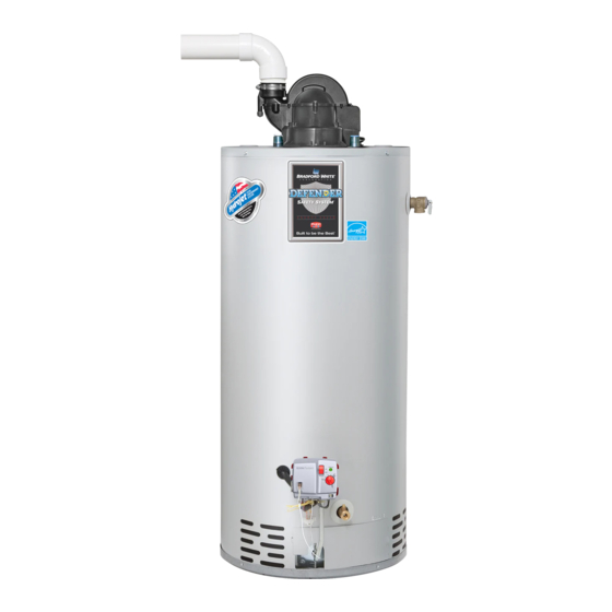
POWER VENT GAS WATER HEATER
A Spanish language version of these instructions is available by
contacting the company listed on the rating plate.
La version espanola de estas instrucciones se puede obtener al escribirle
a la fabrica cuyo nombre aparece en la placa de especificaciones.
INSTALLATION AND OPERATION
WARNING: If the information in these instructions is not
followed exactly, a fire or explosion may result causing
property damage, personal injury, or death.
DO NOT store or use gasoline or other flammable,
combustible, or corrosive vapors and liquids in the
vicinity of this or any other appliance.
WHAT TO DO IF YOU SMELL GAS
DO NOT try to light any appliance.
DO NOT touch any electrical switch; DO NOT use any
phone in your building.
Immediately call your gas supplier from a neighbor's
phone. Follow the gas supplier's instructions.
If you cannot reach your gas supplier, call the fire
department.
Installation and service must be performed by a qualified
installer, service agency or the gas supplier.
For your family's comfort, safety and convenience we recommend this
water heater be installed and serviced by a plumbing professional.
INSTRUCTION MANUAL
FOR YOUR SAFETY
238-53846-00A REV 12/19
Advertisement
Table of Contents

Related Manuals for Bradford White RG1PV50S6X19-264


Summary of Contents for Bradford White RG1PV50S6X19-264
- Page 1 POWER VENT GAS WATER HEATER A Spanish language version of these instructions is available by contacting the company listed on the rating plate. La version espanola de estas instrucciones se puede obtener al escribirle a la fabrica cuyo nombre aparece en la placa de especificaciones. INSTALLATION AND OPERATION INSTRUCTION MANUAL WARNING: If the information in these instructions is not...
- Page 2 CONGRATULATIONS! You have purchased one of the finest water heaters on the market today! This installation, operation and instruction manual will explain in detail the installation and maintenance of your new Power Vented Gas Water Heater. We strongly recommend that you contact a plumbing professional for the installation of this water heater.
-
Page 3: Table Of Contents
TABLE OF CONTENTS Page GENERAL INFORMATION ..............INSTALLATION................. Locating The Water Heater ............Minimum Clearances ..............Venting ..................Specifications for 40 Gal (151.4 L) / 50 Gal (189.2 L) / 60 Gal (227.0 L) ..................12 Vent Pipe Preparation and Joining ........... 16 Combustion Air Supply .............. -
Page 4: General Information
GENERAL INFORMATION This gas-fired water heater’s design is certified by CSA International under the American National Standard Z21.10.1 and CSA 4.1-M, most current editions at the time of manufacture. This is a category III water heater. This water heater must be installed in accordance with local codes or, in the absence of local codes, the National Fuel Gas Code, ANSI Z223.1-Latest Edition) and/or in Canada CAN/CGA B149 Installation Codes (Latest Editions). -
Page 5: Installation
General Information continued- CAUTION This water heater must not be used as a source of construction heat or during the construction phase of any building. Make sure that you check the rating plate and combination gas control on the water heater to be certain that the type of gas being supplied corresponds with the marking on the rating plate and combination gas control. - Page 6 Installation (Locating The Water Heater) continued- The location of this water heater is of the utmost importance. Before installing this water heater, read the installation section of these instructions. After reading these installation and operating instructions, select a location for the water heater where the floor is level and is easily accessible to gas and water supply lines.
- Page 7 Installation (Locating The Water Heater) continued- WARNING DO NOT ATTEMPT TO LIGHT ANY GAS APPLIANCE IF YOU ARE NOT CERTAIN OF THE FOLLOWING: Liquefied petroleum gases/propane gas and natural gas have an odorant added by the gas supplier that aids in the detection of the gas. ...
-
Page 8: Minimum Clearances
Minimum Clearances WARNING Failure to adhere to these installation and operating instructions may create a hazard to life and property and will nullify the warranty. This installation must allow access to the front of the water heater and adequate clearance must be provided for servicing and operating this water heater. - Page 9 Venting continued- Canadian Installations Installations Clearance above grade, veranda, porch, deck or 12 inches 12 inches balcony (30 cm) (30 cm) 4 feet (1.2 m) below or to the side of Clearance to window or door that may be opened 12 inches opening;...
- Page 10 Venting continued- The vent system must terminate so that proper clearances are maintained as cited in local codes or the latest edition of the National Fuel Gas Code, ANSI Z223.1.73.4e and 7.8a, b as follows: 1. Do not terminate near soffit vents or crawl space or other area where condensate or vapor could create a nuisance or hazard or cause property damage.
- Page 11 Venting continued- NOTICE For installations in Canada, field supplied vent piping must comply with CAN/CGA B149.1 (latest edition) and be certified to the Standard For Type BH, Class II, 65°C, Gas Venting Systems, ULC S636. Components of this listed system shall not be interchanged with other vent systems or unlisted pipe/fittings.
-
Page 12: (227.0 L)
Venting System Condensation Condensate formation does not occur in all installations of power vented water heaters but should be protected against on installations where condensation can form in the venting system. Formation of condensation in the venting system of power vented water heaters is dependent upon installation conditions including, but not limited to: ... - Page 13 Venting continued- Make sure the vent pipe terminal is at least 1 in (2.5 cm) away from the edge of the wall. TABLE 1 VENT CONNECTOR LENGTHS FOR 2” (5.1cm) DIAMETER VENT PIPE Terminating Maximum Minimum # of 90 Elbows Straight Length Straight Length (excluding vent...
- Page 14 Venting continued- CONNECTION TO 2” (5.1 CM) CONNECTION TO 3” (7.6 CM) VENT PIPE VENT PIPE Figure 2 IMPORTANT All of the venting connections must be leak checked with a soap and water solution upon initial start-up of the water heater. Any leaks must be repaired before continuing operation of the water heater.
- Page 15 Venting continued- THROUGH THE ROOF VENTING: (VERTICAL VENTING): Cut the necessary holes through the roof and ceiling and install the vent connector as shown in Figure 4. Make sure that the installation meets the local codes and/or The National Fuel Gas Code ANSI Z223.1 (Latest Edition) or CGA/CAN B149 Installation Codes (latest edition).
-
Page 16: Vent Pipe Preparation And Joining
Venting continued- NOTE: For installations requiring both horizontal and vertical runs, the following rule must be followed: Total length of straight pipe (both horizontally and vertically) must NOT exceed the allowable length listed in the Table 3 and 4 for total number of elbows used. TABLE 3 2”... - Page 17 Vent Pipe Preparation and Joining continued- a) CLEANERS, SOLVENTS, PRIMERS AND CEMENTS ARE FLAMMABLE. Do not store or use these materials near heat or open flame, or in the vicinity of other appliances. 2) Use proper cutting, deburring and applicator tools to ensure proper preparation and joining of pipe and fittings.
-
Page 18: Combustion Air Supply
Combustion Air Supply WARNING Liquefied petroleum gases/propane gases are heavier than air and will remain at floor level if there is a leak. Basements, crawl spaces, closets and areas below ground level will serve as pockets for accumulation of leaking gas. Before lighting, smell all around the appliance area for gas. Be sure to smell next to the floor. - Page 19 Combustion Air Supply continued- Each opening must have a minimum free area of 1 in /1000 BTU/hr (2200 /kW) of the total input rating of all gas utilization equipment in the confined space, but not less than 100 in ). One opening must be within 12 in (0.06 m (31 cm) of the top and one within 12 in (31 cm) of the bottom of the enclosure.
-
Page 20: Water Connections
Water Connections NOTE: BEFORE PROCEEDING WITH THE INSTALLATION, CLOSE THE MAIN WATER SUPPLY VALVE. After shutting off the main water supply, open a faucet to relieve the water line pressure to prevent any water from leaking out of the pipes while making the water connections to the water heater. - Page 21 Water Connections continued- WARNING For protection against excessive temperatures and pressure, install temperature and pressure protective equipment required by local codes, but not less than a combination temperature and pressure relief valve certified by a nationally recognized testing laboratory that maintains periodic inspection of production of listed equipment or materials as meeting the requirements of the Standard for Relief Valves and Automatic Gas Shutoff Devices for Hot Water Supply Systems, ANS...
- Page 22 Water Connections continued- WARNING Hydrogen gas can be produced in an operating water heater that has not had water drawn from the tank for a long period of time (generally two weeks or more). HYDROGEN GAS IS EXTREMELY FLAMMABLE. To prevent the possibility of injury under these conditions, we recommend the hot water faucet to be open for several minutes at the kitchen sink before you use any electrical appliance which is connected to the hot water system.
-
Page 23: Gas Connections
Gas Connections WARNING Prior to connecting the gas supply line to a gas fired water heater, ensure that the gas supply line does not have moisture/water or dirt/scale inside the gas line. Commonly this check is done at the lowest point in the gas distribution system prior to gas burning appliances. -
Page 24: Electrical Connections
Gas Connections continued- CAUTION The water heater and individual shutoff valve must be disconnected from the gas supply piping system during any pressure testing of the system at test pressures in excess of 1/2 psi (3.5 kPa). The water heater must be isolated from the gas supply piping system by closing its manual shutoff valve during any pressure testing of the gas supply system at test pressures equal to or less than 1/2 psi (3.5 kPa). -
Page 25: Wiring Diagram
Wiring Diagram Figure 6... -
Page 26: General Operation
GENERAL OPERATION WARNING Water heaters are heat producing appliances. To avoid damage or injury there must be no materials stored against the water heater or vent-air intake system, and proper care must be taken to avoid unnecessary contact (especially by children) with the water heater and vent-air intake system. -
Page 27: Lighting & Shutdown Instructions
Lighting & Shutdown Instructions... -
Page 28: Thermostat Adjustment
Thermostat Adjustment The thermostat dial is adjusted to its lowest setting when shipped from the factory. When adjusting the thermostat, it should be remembered that lower temperature settings are more energy efficient. To adjust the thermostat, turn the dial clockwise until the minimum acceptable temperature is set. It is suggested that the starting point setting not exceed the 120°F (49°C) or “HOT”... -
Page 29: Burner Flame Check
Burner Flame Check Steel Burner: These models are equipped with self-adjusting air mixture and do not have an adjustable air shutter (see Figure 8). At periodic intervals a visual check of the main burner and pilot flames should be made to determine if they are burning properly. - Page 30 Maintenance continued- The following maintenance should be performed by a qualified service technician at the minimum periodic intervals suggested below. In some installations, the maintenance interval may be more frequent depending on the amount of use and the operating conditions of the water heater. Regular inspection and maintenance of the water heater and vent-air intake system will help to insure safe and reliable operation.
- Page 31 Maintenance continued- Do not block or in any way restrict jacket air inlet slots located at the bottom front of the water heater. Do not operate water heater with jumpered, altered, loosely tightened or absent controls and/or components. Do not operate water heater with replacement controls and/or components which are not exact duplicates of original equipment.
- Page 32 Maintenance continued- WARNING When lifting lever of the combination temperature and pressure relief valve, hot water will be released under pressure. Be careful that any released water does not result in bodily injury or property damage. 6. At least once a year, check the combination temperature and pressure relief valve to ensure that the valve has not become encrusted with lime.
- Page 33 Maintenance continued- CAUTION FOR YOUR SAFETY, DO NOT ATTEMPT REPAIR OF COMBINATION GAS CONTROL, BURNERS OR GAS PIPING. REFER REPAIRS TO A QUALIFIED SERVICE TECHNICIAN. Contact your supplier or plumbing professional for replacement parts or contact the company at the address given on the rating plate of the water heater. Provide the part name, model and serial numbers of the water heater when ordering parts.
-
Page 34: Troubleshooting
Troubleshooting LED Status Control Status Probable Cause None (LED not on Electrical power Control power switch in “OFF” position. or flashing) not present. Supply voltage interrupted. Stand-by mode, One short flash Thermostat is Temperature demand is satisfied (no call for every four satisfied (no heat). - Page 35 Troubleshooting continued- LED Status Control Status Probable Cause Pressure switch or 1. Pressure switch tubing kinked or blocked. blower 2. Vent blockage or improper vent temperature configuration. Six flashes-two switch opened 3. Vent termination being affected by windy flashes, three during burner conditions.
- Page 36 Troubleshooting continued- Control Sequence of Operation Start up Sequence Upon powering up, the control checks for the presence of the vapor sensor, if the resistance is in the expected range the control will begin normal operation after 5 to 8 seconds. Normal Heating Sequence 1.
-
Page 37: Parts Diagram
PARTS DIAGRAM PART NAME AND DESCRIPTION 1. Blower Assembly 12. Anode–Nipple 2. Temp. Switch 13. T&P Relief Valve Opening 3. Pressure Switch 14. Pilot Assembly 4. Flue Baffle 15. Main Burner Orifice 5. Honeywell Gas Control Valve 16. Gas Feedline 6. -
Page 38: Space Heating
THE FOLLOWING INSTRUCTIONS ARE FOR INSTALLATION OF: GAS WATER HEATERS SUITABLE FOR WATER (POTABLE) HEATING AND SPACE HEATING 1. All piping components connected to this water heater for space heating applications must be suitable for use with potable water. In Massachusetts, space heating piping length must NOT exceed 50 ft. -
Page 39: Notes
NOTES... - Page 40 NOTES...