Advertisement
Quick Links
OVERVIEW AND INSTALLATION
Refer to the instructions with the aircraft to determine the optimum position for installing the receiver. In some aircraft it's recommended
to fi rst wrap the receiver in protective foam, and then use hook-and-loop material to mount it to the aircraft.
IMPORTANT! Pay close attention to how the receiver/antenna is oriented inside the model. It's best to keep the antenna
unobstructed from the outside of the model as much as possible.
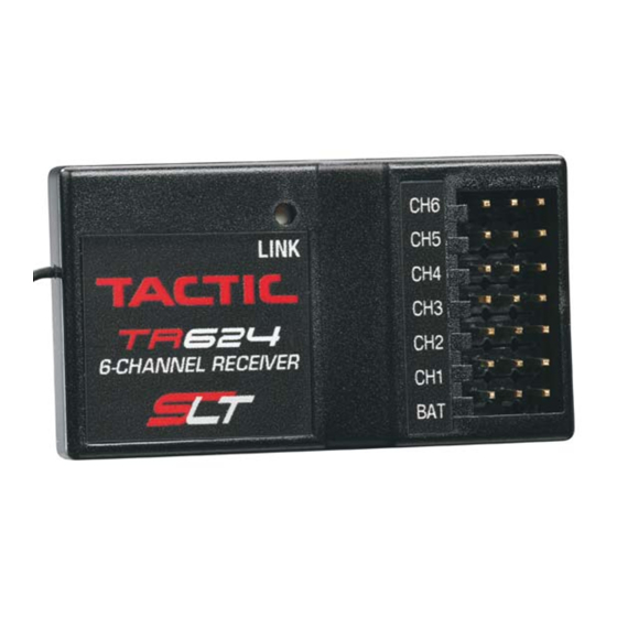
LINK THE RECEIVER TO THE TACTIC/SLT COMPATIBLE TRANSMITTER
Linking the TR624 receiver to the Tactic/SLT compatible transmitter ensures sole communication between the two, and prevents
other transmitters from being able to control the receiver.
1. Turn on the Tx.
2. Apply power to the Rx.
3. If the Rx LED fl ashes once and then stays on, the Rx is
already linked to the Tx and you can skip to the next section.
Otherwise, insert a small diameter screwdriver through the hole
marked "LINK" and press the pushbutton until the Rx LED glows
red and then turns off after about one second.
If the receiver is powered without the transmitter being turned on, or signal from the transmitter is not recognized by the receiver,
the receiver will go to failsafe mode as described in the following section.
FAILSAFE FUNCTION
The radio system's failsafe function is controlled by the TR624 receiver, which engages in the event that the signal from the Tx
somehow becomes interrupted. In such case, channels 1, 2, 4, 5, and 6 will hold their last recognized position.
Throttle, channel 3, however, can move to a position which is pre-set by the user during the linking process. The factory default
failsafe position for channel 3 is to move to 0% throttle. The throttle's failsafe position can be manually set to any other position if
desired, as follows:
1. IMPORTANT: Make sure the throttle channel's servo reverse
setting is in the correct position for the application.
2. Apply power to the Tx, then the Rx.
3a. If using an ESC: do NOT arm the ESC, or attempt to adjust
the throttle's failsafe position if the ESC is armed. NOTE: If you're
using an ESC which has a signal loss feature, its pre-set failsafe
position will be irrelevant as the receiver's failsafe function will
cease the throttle operation if the signal is lost.
3b. If using a combustion engine: do NOT attempt to adjust the
throttle's failsafe position while the engine is operating.
SYSTEM AND RANGE CHECK
Check the instruction manual included with the Tactic radio for the proper steps to perform a system check before fl ight.
WARNING! Always make sure that power is applied to the transmitter BEFORE applying power to the receiver and servos,
and the Tx throttle stick is at minimum (idle) position. Failure to do so could result in the model becoming uncontrollable
and cause a safety hazard. It's best to check the system with the propeller removed from the aircraft. Always perform
This receiver is capable of full-range operation
for small electric and sport scale aircraft types.
Its SLT protocol makes it compatible with all
Tactic brand 2.4GHz aircraft transmitters, and
other brand radios that include the SLT protocol.
4. Release the "LINK" button.
5. If the linking is successful, the Rx LED will fl ash once and
then remain ON.
6. Test for proper Tx/Rx functionality before use. If the radio
doesn't appear to have become properly bound, repeat steps
1–5 above.
4. Move the Tx throttle stick to the desired throttle failsafe position.
5. Press and hold the receiver's "LINK" button. The Rx's LED
should blink twice. Release the LINK button, and the LED should
stay on continuously. The Tx and Rx should now be linked, with
the throttle failsafe in the new position as set above.
6. Prior to fl ight, check the position of the failsafe. It's best to
check the system with the propeller removed from the aircraft
and the aircraft restrained.
TM
2.4GHz 6-CHANNEL RECEIVER
Advertisement

Related Manuals for Tactic TR624


Summary of Contents for Tactic TR624
- Page 1 FAILSAFE FUNCTION The radio system’s failsafe function is controlled by the TR624 receiver, which engages in the event that the signal from the Tx somehow becomes interrupted. In such case, channels 1, 2, 4, 5, and 6 will hold their last recognized position.
- Page 2 1-YEAR WARRANTY Tactic warrants this product to be free from defects in materials and workmanship for a period of one (1) year from the date of purchase. For service on your Tactic product if purchased in the U.S.A.