Agilent Technologies U2300A Series User Manual
Usb multifunction data acquisition devices
Hide thumbs
Also See for U2300A Series:
- Programming manual (169 pages) ,
- Quick reference manual (91 pages)

Related Manuals for Agilent Technologies U2300A Series


Summary of Contents for Agilent Technologies U2300A Series
- Page 1 Agilent U2300A Series USB Multifunction Data Acquisition Devices User’s Guide Agilent Technologies...
- Page 2 FAR 12.211 (Technical Data) and 12.212 (Computer Software) and, for the Department of Defense, DFARS 252.227-7015 (Technical Data - Commercial Items) and DFARS 227.7202-3 (Rights in Commercial Computer Software or Com- puter Software Documentation). U2300A Series DAQ User’s Guide...
- Page 3 The following general safety precautions must be observed during all phases of this instrument. Failure to comply with these precautions or with specific warnings elsewhere in this manual violates safety standards of design, manufacture, and intended use of the instrument. Agilent Technologies, Inc. assumes no liability for the customer’s failure to comply with these requirements.
- Page 4 • Always use dry cloth to clean the device. Do not use ethyl alcohol or any other volatile liquid to clean the device. • Do not permit any blockage of the ventilation holes of the device. U2300A Series DAQ User’s Guide...
- Page 5 “Monitoring and Control Instrument” product. The affixed product label is shown as below: Do not dispose in domestic household waste To return this unwanted instrument, contact your nearest Agilent office, or visit: http://www.agilent.com/environment/product for more information. U2300A Series DAQ User’s Guide...
- Page 6 Agilent Measurement Manager application software. Connector Pins Configuration describes the connector pins configuration of the U2300A Series USB DAQ and the signal connection between the U2300A and external devices. Features and Functions includes the information for better understanding on the features and functions of the U2300A series USB DAQ.
- Page 7 20-October-2006 Mack Soh Date Quality Manager For further information, please contact your local Agilent Technologies sales office, agent or distributor, or Agilent Technologies Deutschland GmbH, Herrenberger Straße 130, D 71034 Böblingen, Germany. Template: A5971-5302-2, Rev. B.01 U2300 series Rev 1.0...
- Page 8 Regulatory Information for Canada ICES/NMB-001:1998 This ISM device complies with Canadian ICES-001. Cet appareil ISM est confomre à la norme NMB-001 du Canada. Regulatory Information for Australia/New Zealand This ISM device complies with Australian/New Zealand AS/NZS 2064.1 VIII U2300A Series DAQ User’s Guide...
-
Page 9: Table Of Contents
D. Install the Agilent Measurement Manager E. Connect Your Device to the PC F. Launch Your Agilent Measurement Manager L-Mount Kit Installation General Maintenance Connector Pins Configuration Connector Pins Configuration Analog Input Signal Connection Types of signal sources Input configurations U2300A Series DAQ User’s Guide... - Page 10 Analog output Characteristics and Specifications Product Characteristics Product Specifications Basic multifunction DAQ device specifications High density multifunction DAQ device specifications Electrical Measurement Specifications Basic multifunction USB DAQ device specifications High density multifunction USB DAQ device specifications U2300A Series DAQ User’s Guide...
- Page 11 Contents Calibration Self-Calibration U2300A Series DAQ User’s Guide...
- Page 12 Contents U2300A Series DAQ User’s Guide...
- Page 13 Figure 3-2 Burst mode enabled and disabled during data acquisition Figure 3-3 Analog output operation mode Figure 3-4 General purpose digital I/O of Agilent U2300A series Figure 3-5 General purpose digital counter Figure 3-6 Totalizer mode Figure 3-7 Pre-trigger...
- Page 14 U2300A Series DAQ User’s Guide...
- Page 15 Trigger type for single-shot acquisition of continuous mode Table 3-13 Trigger type for continuous acquisition of continuous mode Table 4-1 Analog input product specifications for basic multifunction DAQ device Table 4-2 Analog output product specifications for basic multifunction DAQ device U2300A Series DAQ User’s Guide...
- Page 16 Analog input electrical measurement specifications for basic multifunction USB DAQ device Table 4-18 Analog output electrical measurement specifications for basic multifunction USB DAQ device Table 4-19 Analog input electrical measurement specifications for high density multifunction USB DAQ device U2300A Series DAQ User’s Guide...
- Page 17 Table 4-20 Analog output electrical measurement specifications for high density multifunction USB DAQ device Table 4-20 Analog output electrical measurement specifications for high density multifunction USB DAQ device U2300A Series DAQ User’s Guide XVII...
- Page 18 XVIII U2300A Series DAQ User’s Guide...
-
Page 19: Getting Started
F. Launch Your Agilent Measurement Manager L-Mount Kit Installation General Maintenance This chapter provides an overview of the U2300A series, the product outlook, product dimension, and product layout. This chapter also contains instructions on how to get started with the U2300A series that begins from system... -
Page 20: Introduction
The Agilent U2300A series USB multifunction data acquisition (DAQ) devices can operate as a standalone unit or modular unit (when used in a chassis). The U2300A series consists of basic multifunction models (U2351A, U2352A, U2353A, and U2354A) and high density multifunction models (U2355A, U2356A, and U2331A). -
Page 21: Product Overview
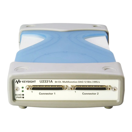
Getting Started Product Overview Product outlook Top view Plastic Casing Front view Connector 1 AI/AO Indicator Power Indicator Connector 2 Rear view USB Inlet Power Inlet U2300A Series DAQ User’s Guide... -
Page 22: Product Dimension
Getting Started Product dimension Without plastic casing With plastic casing Top view Top view 174.54 mm 182.40 mm Front view Front view 25.00 mm 44.00 mm 105.00 mm 120.00 mm U2300A Series DAQ User’s Guide... - Page 23 Getting Started Terminal Block Overview Front view 85.20 mm 103.00 mm Side view 42.96 mm 28.40 mm U2300A Series DAQ User’s Guide...
-
Page 24: Standard Purchase Items Checklist
✔ USB extension cable ✔ L–Mount kit (used with modular instrument chassis) ✔ Agilent U2300A Series Data Acquisition Devices and Agilent Measurement Manager Quick Start Guide ✔ Agilent USB Modular Instrument U2300A & U2700A Series Product Reference CD- ROM ✔... -
Page 25: Software Installation
Software Installation If you would like to use the U2300A series USB DAQ devices with the Agilent Measurement Manager application software, follow the step- by- step instructions as shown in the following flowchart. • N O T E Agilent VEE, LabVIEW, MATLAB or Microsoft Visual Studio), you can skip steps D and F in the following flowchart. -
Page 26: Check Your System Requirements
• Microsoft.NET Framework version 1.1 and 2.0 • Agilent T&M Toolkit Redistributable Package 2.1 patch Video Super VGA (800x600) 256 colors or higher 1 Available in Agilent Automation-Ready CD. 2 Bundled with Agilent Measurement Manager application software installer U2300A Series DAQ User’s Guide... -
Page 27: Install The Agilent Io Libraries Suite
InstallShield Wizard and choose the options according to your preferences. For more information to install the Agilent IO Libraries Suite, refer to Agilent Technologies USB/LAN/GPIB Interfaces Connectivity Guide available in the Agilent Automation- Ready CD with the file name called “connectivity_guide.pdf”. -
Page 28: Install The Hardware Driver
3 If the menu does not launch automatically, go to Start > Run (on the Windows Start menu) and type <drive>:\Driver\ Hardware\setup_hw.exe, where drive is your CD- ROM drive. Click OK to begin installation. 4 The following dialog will appear. Click Next > to begin the installation. U2300A Series DAQ User’s Guide... - Page 29 Getting Started 5 If you have previous hardware driver version, the dialog box will have the Modify, Repair and Remove options as shown below. Choose the option you like and click Next > to proceed. U2300A Series DAQ User’s Guide...
- Page 30 Click Next > to proceed. 7 Choose the option you like and the following dialog will appear showing all the components that will be installed. Click Install to begin installation. U2300A Series DAQ User’s Guide...
-
Page 31: Install The Agilent Measurement Manager
• You must have Administrator privileges to install Agilent IO Libraries Suite and to run Connection Expert. 1 Verify that you have the hardware driver installed. 2 Select Measurement Manager on the Agilent Modular Products Installation Menu to begin the installation. U2300A Series DAQ User’s Guide... - Page 32 5 If you do not have the Agilent T&M Toolkit 2.1 Runtime version, Microsoft .NET Framework version 1.1 and 2.0, and Agilent T&M Toolkit Redistributable Package 2.1 patch installed, the InstallShield Wizard software pre- requisite will appear as shown in the following figure. U2300A Series DAQ User’s Guide...
- Page 33 Agilent Measurement Manager installation. 10 Read the License Agreement carefully. If you accept the terms, select the radio button that labeled I accept the terms in the license agreement and click Next > to continue. U2300A Series DAQ User’s Guide...
- Page 34 TERMS. IF YOU DO NOT AGREE TO ALL OF THESE TERMS, YOU MAY RETURN ANY UNOPENED LICENSED MATERIALS FOR A FULL REFUND. IF THE LICENSED MATERIALS ARE BUNDLED OR PRE-LOADED WITH ANOTHER PRODUCT, YOU MAY RETURN THE ENTIRE UNUSED PRODUCT FOR A FULL REFUND. U2300A Series DAQ User’s Guide...
-
Page 35: Connect Your Device To The Pc
2 Insert the DC output plug from the AC/DC power adapter to the power jack on the rear panel of the USB device. 3 Connect any of the U2300A series instrument to any USB ports on your PC with the USB cable. - Page 36 Each time a USB device is plugged in, this dialog box will appear. To configure or disable this dialog, select an option in the Show this dialog panel and click OK. U2300A Series DAQ User’s Guide...
- Page 37 Getting Started 9 The USB device is now ready for usage. Before proceeding, you may verify your connected device using Agilent Con- N O T E nection Expert. U2300A Series DAQ User’s Guide...
-
Page 38: Launch Your Agilent Measurement Manager
2 The Select USB Device dialog box will appear. It will show all the devices that are connected to your PC. To start the application, select a DAQ device and click OK to establish the connection. U2300A Series DAQ User’s Guide... -
Page 39: L-Mount Kit Installation
(front end of the casing) in an outward direction. Then, lift the plastic body casing and remove it from your DAQ device. Using a Philips screw driver, screw the L- Mount kit to your DAQ device. U2300A Series DAQ User’s Guide... - Page 40 DAQ module perpendicularly and ensure that the 55- pin backplane connector is at the bottom side of the DAQ module. Your DAQ device is now ready to be plug into an instrument chassis. U2300A Series DAQ User’s Guide...
-
Page 41: General Maintenance
Then, lift the plastic body casing and remove it from your DAQ device. 3 Holding your DAQ device, shake out any dirt that may have accumulated on the panel of your DAQ device. 4 Wipe your DAQ device with a dry cloth. U2300A Series DAQ User’s Guide... - Page 42 Getting Started U2300A Series DAQ User’s Guide...
- Page 43 Connector Pins Configuration Connector Pins Configuration Analog Input Signal Connection Types of signal sources Input configurations This chapter describes the connector pins configuration of the U2300A series USB DAQ and the signal connection between the U2300A and external devices. Agilent Technologies...
-
Page 44: Connector Pins Configuration
Connector Pins Configuration Connector Pins Configuration The U2300A series DAQ is equipped with 68–pin very high density cable interconnect (VHDCI) type connectors. These connector pins are used for digital input/output, analog input/output, counters and other external reference/trigger signal. Pins Configuration of Connector 1 for U2331A, U2355A, U2356A... - Page 45 Connector Pins Configuration (AIH101..132) and (AIL101..132) are for differential mode connection pair. N O T E Pins Configuration of Connector 2 for U2355A, U2356A, U2331A U2300A Series DAQ User’s Guide...
- Page 46 Connector Pins Configuration Pins Configuration for U2352A, U2354A (AIH101..108) and (AIL101..108) are for differential mode connection pair. N O T E U2300A Series DAQ User’s Guide...
- Page 47 Connector Pins Configuration Pins Configuration for U2351A, U2353A (AIH101..108) and (AIL101..108) are for differential mode connection pair. N O T E U2300A Series DAQ User’s Guide...
-
Page 48: Table 2-1 68-Pin Vhdci Connector Pins Descriptions
Input D_GND Output of counter <301,302> COUNT<301,302>_UPDOWN Input D_GND Up/Down of counter <301,302> EXT_TIMEBASE Input D_GND External Timebase D_GND Digital ground DIO501<7,0> D_GND Programmable DIO of Channel 501 DIO502<7,0> D_GND Programmable DIO of Channel 502 U2300A Series DAQ User’s Guide... -
Page 49: Table 2-2 Ssi Connector Pins Descriptions
Functionality +12V +12 V power from backplane Ground BRSV Reserved pin TRIG0~TRIG7 Trigger bus 0 ~ 7 STAR_TRIG Star trigger CLK10M 10MHz reference clock USB_VBUS USB bus power, +5 V USB_D+, USB_D- USB differential pair U2300A Series DAQ User’s Guide... - Page 50 Connector Pins Configuration Table 2-2 SSI connector pins descriptions LBL <0..7> and Reserved pin LBR <0..7> GA0, GA1, GA2 Geographical address pin U2300A Series DAQ User’s Guide...
-
Page 51: Analog Input Signal Connection
Connector Pins Configuration Analog Input Signal Connection The U2300A series DAQ provides up to 64 single–ended (SE) or 32 differential analog input (DI) channels. The analog signal is converted to digital represented value by the A/D converter. In order to obtain a more accurate measurement... -
Page 52: Input Configurations
The following figure illustrates the RSE mode. Figure 2-1 Floating source and RSE input connections When more than two floating sources are connected, these sources are N O T E referenced to the same common ground. U2300A Series DAQ User’s Guide... -
Page 53: Figure 2-2 Ground-Referenced Sources And Nrse Input
Hence, any potential difference of the common mode ground between signal ground and the signal ground on DAQ board will be rejected by the instrumentation amplifier. Figure 2-2 Ground-referenced sources and NRSE input connections U2300A Series DAQ User’s Guide... -
Page 54: Figure 2-3 Ground-Referenced Source And Differential Input Mode
The differential input mode provides two inputs that respond to the difference of the signal voltage. The analog input of the U2300A series DAQ has its own reference ground or signal return path. The differential mode can be used for the common- mode noise rejection if the signal source is ground- referenced. -
Page 55: Figure 2-4 Floating Source And Differential Input
Amplifier. The noise couples in differential input mode are less compared to the single- ended mode. Figure 2-4 Floating source and differential input • Agilent U2300A series DAQ is designed with high input impedance. N O T E Please ensure that all the connection are connected properly before acquiring any data. - Page 56 Connector Pins Configuration U2300A Series DAQ User’s Guide...
- Page 57 Analog input Analog output This chapter describes the features and functions of the U2300A series USB DAQ devices. This includes the operations of the analog input operation mode, analog output operation mode, digital I/O, and general purpose digital counter. This chapter also explains the trigger sources.
-
Page 58: Features And Functions
• Programmable bipolar and unipolar analog input. • Self- calibration supported. • USBTMC 488.2 compliant. • Hi- Speed USB 2.0 interface. • Multiple trigger sources none (intermediate trigger), external analog/digital trigger, and SSI/star trigger (used with modular chassis). U2300A Series USB DAQ User’s Guide... -
Page 59: Analog Input Operation Mode
±1.25 V to ±10 V (16- bit ADC), except for U2331A with ±0.05 V to ±10 V (12- bit ADC). The following diagram illustrates the functional block diagram of the U2300A series DAQ device. According to the functional block diagram, when the U2300A... -
Page 60: Figure 3-1 Functional Block Diagram Of U2300A Series Daq
Features and Functions Figure 3-1 Functional block diagram of U2300A series DAQ device There are two different modes of analog input operation, which are the polling and continuous. Table 3-1 Analog input operation overview Operation Modes Types of Acquisition Analog Input... - Page 61 On the other hand, the continuous acquisition allows you to acquire data continuously until a STOP command is sent. The SCPI commands below are used to start the acquisition process: • Single- shot acquisition: DIGitize • Continuous acquisition: U2300A Series USB DAQ User’s Guide...
- Page 62 Sampling rate Specify the sampling rate of each AI channel. Since the U2300A series DAQ devices comes with multiplexing analog input, the maximum sampling rate depends on the ADC’s sampling rate and the entry number in the scan list.
-
Page 63: Scan List (For Continuous Mode Only)
Features and Functions Scan list (for continuous mode only) You are required to set up the scan list to include all desired analog input channels. By default, the U2300A series scans only CH 101 with the following settings. • Range: ±10 V •... -
Page 64: Burst Mode
The following figure illustrates an example of burst mode. Example: Sampling rate: 1 kSa/s Number of sampling channels: three Scan list sequence: 101, 102, 103 Figure 3-2 Burst mode enabled and disabled during data acquisition U2300A Series USB DAQ User’s Guide... -
Page 65: A/D Data Conversion
To perform a sample calculation of the conversion, take the U2356A as an example. The resolution of U2356A is 16 bits and the range is taken as 10 V. The Int16b value calculated using conversion algorithm is 12768. U2300A Series USB DAQ User’s Guide... - Page 66 Features and Functions Hence, the 16 bits binary read back calculation will be as follows. <11100000> <00110001> = 12768 The raw data provided by U2300A series DAQ devices is in the byte order N O T E of LSB first. Bipolar ×...
-
Page 67: Ai Data Format
FSR–1LSB 9.9976 V 4.9988 V 2.9994 V 7FFX Midscale +1LSB 5.00244 V 2.50122 V 1.25061 V 001X Midscale 2.5 V 1.25 V 000X Midscale –1LSB 4.9976 V 2.4988 V 1.2494 V FFFX –FSR 800X U2300A Series USB DAQ User’s Guide... -
Page 68: Table 3-5 Analog Input Range And Digital Code Output For
1.249981 V 7FFF Midscale +1LSB 5.000153 V 2.500076 V 1.250038 V 0.625019 V 0001 Midscale 2.5 V 1.25 V 0.625 V 0000 Midscale –1LSB 4.999847 V 2.499924 V 1.249962 V 0.624981 V FFFF –FSR 8000 U2300A Series USB DAQ User’s Guide... -
Page 69: Analog Output Operation Mode
Analog Output Operation Mode There are two D/A channels that are available in the U2300A series DAQ devices. The two analog outputs are capable of supplying output voltages in the range of 0 to 10 V and ±10 V (12- bit for U2355A, U2356A, U2331A and 16- bit for U2351A, U2353A). -
Page 70: Table 3-7 Analog Output Operation Overview
// Changes output from 2.5 VDC to 3.2 -> SOUR:VOLT –3.2, // Changes output from 3.2 VDC to –3.2 (@201) -> SOUR:VOLT? (@202) // To query the state of CH 202 <- 0 // By default, CH 202 is 0 VDC U2300A Series USB DAQ User’s Guide... - Page 71 You can use the following SCPI commands in arbitrary mode: DATA[:USER] APPLy:USER For further information, refer to the Agilent U2300A Series USB Multifunc- N O T E tion Data Acquisition Programming Guide . Example 3, To output a sine wave via CH 201 ->...
- Page 72 // Set both channel’s output to 3.5 kHz -> SYST:ERR? <- +0, “No Error” // To check for any error, this command can be ignored if this operations is not required -> OUTP ON // Turn on output U2300A Series USB DAQ User’s Guide...
-
Page 73: D/A Reference Voltage
2nd data 3rd data 3rd data 4th data 4th data (0000 0200) specifying the actual data length only, not actual data. Data length CH 201/202 CH 201/202 CH 201/202 CH 201/202 (200 bytes long) U2300A Series USB DAQ User’s Guide... -
Page 74: Table 3-8 Digital Code And Voltage Output Table For Bipolar Setting
Analog Output Voltage output (with internal reference of +10 V) 0x0FFF Vref * (4095/4096) 9.9975 V 0x0800 Vref * (2048/4096) 5.000 V 0x0001 Vref * (1/4096) 0.0024 V 0x0000 Vref * (0/4096) 0.000 V U2300A Series USB DAQ User’s Guide... -
Page 75: Table 3-10 Digital Code And Voltage Output Table For Bipolar Setting
Digital Code (Hex) Analog Output Voltage output (with internal reference of +10 V) 0xFFFF Vref * (65535/65536) 9.999847 V 0x8000 Vref * (32768/65536) 5.00000 V 0x0001 Vref * (1/65536) 0.000152 V 0x0000 Vref * (0/65536) U2300A Series USB DAQ User’s Guide... -
Page 76: Digital I/O
As the system starts up and reset, all the I/O pins are reset to the input configuration and in high impedance. Figure 3-4 General purpose digital I/O of Agilent U2300A series DAQ U2300A Series USB DAQ User’s Guide... - Page 77 Configure the digital channel to INPUT and read back the value Example 1: -> CONF:DIG:DIR INP,(@501) //Configure the CH 501 to digital output state -> MEAS:DIG? (@501) //To read back the digital value at channel 501 <- 23 U2300A Series USB DAQ User’s Guide...
- Page 78 <-! VI_ERROR_TMO: A timeout occurred -> SOUR:DIG:DATA? (@502) // CH 502 has been set to input state, hence, it cannot perform output activity <-! VI_ERROR_TMO: A timeout occurred U2300A Series USB DAQ User’s Guide...
-
Page 79: General Purpose Digital Counter
Features and Functions General Purpose Digital Counter The U2300A series DAQ device has two independent 31–bit up/down counters to measure the input channels, which are TTL compatible. It has a programmable counter clock up to 12 MHz or clock generation. Refer to... -
Page 80: Figure 3-6 Totalizer Mode
COUNT_GATE will enable the counting after the totalize function has been enabled and the COUNT_OUT pin will output a series of pulses as shown below. Figure 3-6 Totalizer mode The output pulse width is at 20.8 ns. N O T E U2300A Series USB DAQ User’s Guide... - Page 81 -> MEAS:COUN:TOT? (@301) <- 105 -> MEAS:COUN:DATA? (@301) <- 105 -> COUN:ABOR (@301) // Abort all counter operation -> COUN:TOT:CLE (@301) // Clear Count value -> MEAS:COUN:TOT? (@301) <- 0 -> MEAS:COUN:DATA? (@301) <- 0 U2300A Series USB DAQ User’s Guide...
- Page 82 • The input frequency measurable range is from 0.1 Hz to 6 MHz. N O T E • The pulse width measurement is in the range of 0.167 s to 178.956 s. U2300A Series USB DAQ User’s Guide...
- Page 83 -> MEAS:COUN:FREQ? (@301) <- 5.499542 -> COUN:FUNC? (@301) <- FREQ // Function automatic set to FREQ -> MEAS:COUN:PER? (@301) <- 0.1818333 -> COUN:FUNC? (@301) <- PER // Function automatic set to -> MEAS:COUN:PWID? (@301) <- 0.12725 U2300A Series USB DAQ User’s Guide...
- Page 84 // Must set the external Clock value (KHz) -> COUN:CLK:EXT 10000,(@301) -> COUN:CLK:EXT? (@301) <- 10000 Direction of the counter and the initial value of the counter are not N O T E important for this mode. U2300A Series USB DAQ User’s Guide...
-
Page 85: Trigger Sources
Features and Functions Trigger Sources The Agilent U2300A series USB DAQ devices provides flexible trigger options for various applications. There are four types of trigger sources: • none (immediate trigger) • digital trigger • analog trigger • star trigger Users can configure the trigger source for A/D and D/A operations remotely. -
Page 86: Trigger Types
Refer to the following figure for further illustration. Due to memory limitation on hardware, the maximum sample points is N O T E only up to 8 MSa. Figure 3-7 Pre-trigger U2300A Series USB DAQ User’s Guide... -
Page 87: Figure 3-8 Middle-Trigger
As illustrated in the following figure, the sample point are set to two. Total of two sample points are taken after the trigger starts. U2300A Series USB DAQ User’s Guide... -
Page 88: Figure 3-9 Post-Trigger
48 MHz is set as Timebase clock, the delay time is in the range of 20.8 ns to 89.47 s. If the Timebase clock is from external clock (48 MHz to 1 MHz), the delay time can be varied by user’s setting. U2300A Series USB DAQ User’s Guide... -
Page 89: Digital Trigger
It is used when a rising or falling edge is detected on the digital signal. Positive condition is used when it triggers from low to high, while high to low when the negative condition is used. Figure 3-11 Positive and negative edge of digital trigger. U2300A Series USB DAQ User’s Guide... -
Page 90: Analog Trigger
Features and Functions Analog trigger There are three analog trigger conditions in U2300A series DAQ and the trigger conditions are as follows: • Above high • Below low • Window It uses two threshold voltages, which are Low- Threshold and High- Threshold. -
Page 91: Figure 3-13 Below Low Trigger Condition
Low- Threshold voltage. In this trigger condition, the High- Threshold voltage is not used. The following figure illustrates the above high analog trigger condition. Figure 3-13 Below low trigger condition U2300A Series USB DAQ User’s Guide... -
Page 92: Figure 3-14 Window Trigger Condition
The window trigger condition is shown in the following diagram. The trigger signal is generated when the input analog signal falls within the voltage range of the High- Threshold and Low- Threshold. Figure 3-14 Window trigger condition U2300A Series USB DAQ User’s Guide... -
Page 93: Scpi Programming Examples
// To check acquisition completion for DIG <- NO // Wait for trigger // Five seconds delay after the trigger event -> WAV:STAT? <- DATA -> WAV:COMP? <- YES <- WAV:DATA? <- #800002000 // Raw data returned by DAQ <byte><byte>... U2300A Series USB DAQ User’s Guide... - Page 94 // Above high Threshold condition -> TRIG:ATRG:LTHR –3 // 3 V high Threshold -> TRIG:TYPE PRE // –3 V low Threshold -> DIG // Pre trigger // Trigger will happen when signal go above 3 V U2300A Series USB DAQ User’s Guide...
- Page 95 -> DIG // Trigger will take place when signal fall below 2 V at channel 133 Middle-trigger and pre-trigger are not allow in RUN mode, NONE trigger N O T E and SONE trigger. U2300A Series USB DAQ User’s Guide...
-
Page 96: Analog Output
// Window trigger condition (–3 V to 3 V) -> OUTP:TRIG:ATRG:HTHR 3 // 3 V high Threshold -> OUTP:TRIG:ATRG:LTHR –3 // –3 V low Threshold -> OUTP:TRIG:TYPE POST -> ROUT:ENAB ON,(@201) -> OUTP ON U2300A Series USB DAQ User’s Guide... - Page 97 -> RUN -> OUTP ON // Important! For SONE mode, execute the RUN/DIG command first before turning on N O T E the output. Channel 133 will only respond to trigger signal during acquisition. U2300A Series USB DAQ User’s Guide...
- Page 98 Features and Functions U2300A Series USB DAQ User’s Guide...
-
Page 99: Characteristics And Specifications
Agilent U2300A Series Multifunction USB DAQ User’s Guide Characteristics and Specifications Product Characteristics Product Specifications Basic multifunction DAQ device specifications High density multifunction DAQ device specifications Electrical Measurement Specifications Basic multifunction USB DAQ device specifications High density multifunction USB DAQ device specifications This chapter specifies the characteristics, environmental conditions, and specifications of the U2300A DAQ device. -
Page 100: Product Characteristics
105.00 mm x 174.54 mm x 25.00 mm (without plastic casing) Terminal block dimension: • 103.00 mm x 85.20 mm x 42.96 mm WEIGHT • 565 g (with plastic casing) • 400 g (without plastic casing) WARRANTY Three years U2300A Series USB DAQ User’s Guide... -
Page 101: Product Specifications
Overvoltage protection Power on: Continuous ±30 V, Power off: Continuous ±15 V Trigger sources External analog/digital trigger, SSI/star trigger Trigger modes Pre- trigger, delay-trigger, post-trigger, and middle-trigger FIFO buffer size Up to 8 MSa U2300A Series USB DAQ User’s Guide... -
Page 102: Table 4-2 Analog Output Product Specifications For Basic Multifunction Daq Device
= 2.0 V minimum, I = 10 µA maximum Input voltage range –0.5 V to +5.5 V Output voltage = 0.45 V maximum, I = 8 mA maximum = 2.4 V minimum, I = 400 µA maximum U2300A Series USB DAQ User’s Guide... -
Page 103: Table 4-4 General Purpose Digital Counter Product Specifications For Basic Multifunction Daq Device
Table 4-6 Digital trigger product specifications for basic multifunction DAQ device Digital Trigger Model Number U2351A | U2352A | U2353A | U2354A Compatibility TTL/CMOS Response Rising or falling edge Pulse width 20 ns minimum U2300A Series USB DAQ User’s Guide... -
Page 104: Table 4-7 Calibration Product Specifications For Basic Multifunction Daq Device
[1] System Synchronous Interface (SSI) and Star-trigger commands are used when modular devices are used in instrument chassis. [2] Maximum external reference voltage for analog output (AO_EXT_REF) is ±10 V. [3] 20 minutes warm-up time is recommended. U2300A Series USB DAQ User’s Guide... -
Page 105: High Density Multifunction Daq Device Specifications
±7.5 V maximum Overvoltage protection Power on: Continuous ±30 V, Power off: Continuous ±15 V Trigger sources External analog/digital trigger, SSI/star trigger Trigger modes Pre-trigger, delay-trigger, post-trigger and middle-trigger FIFO buffer size Up to 8 MSa U2300A Series USB DAQ User’s Guide... -
Page 106: Table 4-10 Analog Output Product Specifications For High Density Multifunction Daq Device
= 2.0 V min, I = 10 µA max Input voltage range –0.5 V to +5.5 V Output voltage = 0.45 V max, I = 8 mA max = 2.4 V min, I = 400 µA max U2300A Series USB DAQ User’s Guide... -
Page 107: Table 4-12 General Purpose Digital Counter Product Specifications For High Density Multifunction Daq Device
Continuous for ±35 V maximum Table 4-14 Digital trigger product specifications for high density multifunction DAQ device Digital Trigger Model Number U2355A | U2356A | U2331A Compatibility TTL/CMOS Response Rising or falling edge Pulse width 20 ns minimum U2300A Series USB DAQ User’s Guide... -
Page 108: Table 4-15 Calibration Product Specifications For High Density Multifunction Daq Device
[1] System Synchronous Interface (SSI) and Star-trigger commands are used when modular devices are used in instrument chassis. [2] Maximum external reference voltage for analog output (AO_EXT_REF) is ±10 V. [3] 20 minutes warm-up time is recommended. U2300A Series USB DAQ User’s Guide... -
Page 109: Electrical Measurement Specifications
±5 mV Slew rate 19 V/µs Rise time 0.9 µs Fall time 0.9 µs Settling time to 1% output error 4 µs Driving capability 5 mA Glitch energy 5 ns-V (Typical), 80 ns-V (Maximum) U2300A Series USB DAQ User’s Guide... - Page 110 2.4109 kHz Number of points: 8192 Fundamental input voltage: FSR –1 dB FS U2353A Sampling Rate: 500 kSa/s U2354A Fundamental Frequency: 4.974 kHz Number of points: 16384 Fundamental input voltage: FSR –1 dB FS U2300A Series USB DAQ User’s Guide...
-
Page 111: High Density Multifunction Usb Daq Device Specifications
0.9 µs 0.9 µs Settling time to 1% output error 4 µs 4 µs Driving capability 5 mA 5 mA Glitch energy 5 ns-V (Typical), 5 ns-V (Typical), 80 ns-V (Maximum) 80 ns-V (Maximum) U2300A Series USB DAQ User’s Guide... - Page 112 Fundamental Frequency: 4.974 kHz Number of points: 16384 Fundamental input voltage: FSR –1 dB FS U2331A Sampling Rate: 3 MSa/s Fundamental Frequency: 29.892 kHz Number of points: 65536 Fundamental input voltage: FSR –1 dB FS U2300A Series USB DAQ User’s Guide...
- Page 113 Agilent U2300A Series USB Multifunction DAQ User’s Guide Calibration Self-Calibration This chapter introduces the procedures to perform calibration process to the U2300A series DAQ devices to minimize A/D measurement errors and D/A output errors. Agilent Technologies...
- Page 114 Calibration Self-Calibration The Agilent U2300A series USB data acquisition devices are factory- calibrated before shipment. The on- board reference voltage are calibrated and measured to ensure measurement accuracy. The device includes a self- calibration function to ensure accuracy of the measurement made under different environment usage.
- Page 115 (tel) (65) 6375 8100 (fax) (65) 6755 0042 Or visit Agilent World Wide Web at: www.agilent.com/find/assist Product specifications and descriptions in this document are subject to change without notice. © Agilent Technologies, Inc., 2006–2009 Printed in Malaysia Fourth Edition, 1 September 2009 U2351-90002 Agilent Technologies...