U-Line 1000 Series User Manual
Hide thumbs
Also See for 1000 Series:
- User manual & service manual (59 pages) ,
- User manual (48 pages) ,
- Use and care manual (24 pages)

Related Manuals for U-Line 1000 Series


Summary of Contents for U-Line 1000 Series
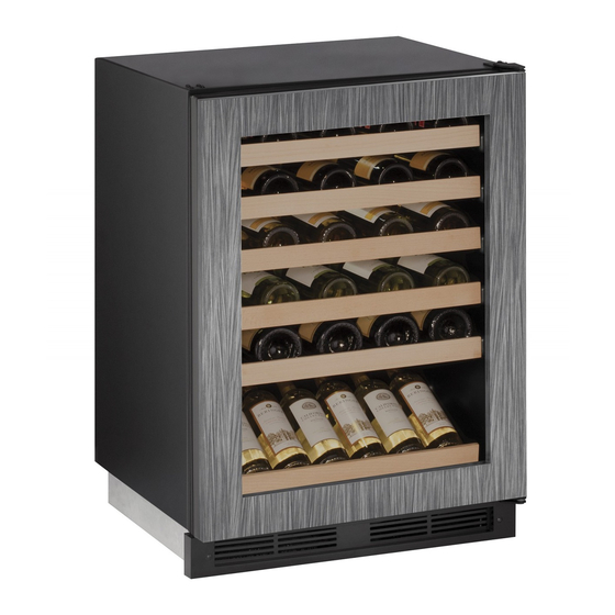
- Page 1 USER GUIDE SAFETY • INSTALLATION & INTEGRATION • OPERATING INSTRUCTIONS • MAINTENANCE • SERVICE RIGHT PRODUCT. RIGHT PLACE. RIGHT TEMPERATURE. SINCE 1962. 1000 Series 1224WC 24" Wine Captain Model ® • •...
-
Page 2: Environmental Requirements
USER GUIDE u-line.com SAFETY • INSTALLATION & INTEGRATION • OPERATING INSTRUCTIONS • MAINTENANCE • SERVICE Environmental Requirements This model is intended for indoor/interior applications only and is not to be used in installations that are open/ exposed to natural elements. - Page 3 USER GUIDE u-line.com SAFETY • INSTALLATION & INTEGRATION • OPERATING INSTRUCTIONS • MAINTENANCE • SERVICE Electrical WARNING SHOCK HAZARD — Electrical Grounding Required. Never attempt to repair or perform maintenance on the unit until the electricity has been disconnected. Never remove the round grounding prong from the plug and never use a two-prong grounding adapter.
-
Page 4: Cutout Dimensions
SAFETY • INSTALLATION & INTEGRATION • OPERATING INSTRUCTIONS • MAINTENANCE • SERVICE Cutout Dimensions PREPARE SITE Your U-Line product has been designed for either free- standing or built-in installation. When built-in, your unit does not require additional air space for top, sides, or rear. -
Page 5: Product Dimensions
USER GUIDE u-line.com SAFETY • INSTALLATION & INTEGRATION • OPERATING INSTRUCTIONS • MAINTENANCE • SERVICE Product Dimensions 23-1/4" (591 mm) (Includes 3/4" [20 mm] Integrated Panel) 34-1/8" to 35-1/8" (867 mm to 892 mm) 24" (610 mm) 3-9/16" (91 mm) -
Page 6: Side-By-Side Installation
USER GUIDE u-line.com SAFETY • INSTALLATION & INTEGRATION • OPERATING INSTRUCTIONS • MAINTENANCE • SERVICE Side-by-Side Installation 3. Place bracket over holes and attach to unit with two screws removed in step 2 using a T-25 Torx driver. Two units may be installed side-by-side. -
Page 7: Anti-Tip Bracket
USER GUIDE u-line.com SAFETY • INSTALLATION & INTEGRATION • OPERATING INSTRUCTIONS • MAINTENANCE • SERVICE Anti-Tip Bracket FLOOR MOUNTED ANTI-TIP INSTALLATION 1. Locate two anti-tip brackets included in the kit. 1. Slide unit out so screws on top of unit are easily accessible. - Page 8 USER GUIDE u-line.com SAFETY • INSTALLATION & INTEGRATION • OPERATING INSTRUCTIONS • MAINTENANCE • SERVICE 4. Remove the unit. Using a square, extend center line 5. Place the anti-tip brackets on the floor against the line “B” (see chart below). This line serves as the back drawn for the outer edge.
-
Page 9: General Installation
USER GUIDE u-line.com SAFETY • INSTALLATION & INTEGRATION • OPERATING INSTRUCTIONS • MAINTENANCE • SERVICE General Installation INSTALLATION 1. Plug in the power/electrical cord. LEVELING INFORMATION 1. Use a level to 2. Gently push the unit into position. Be careful not to confirm the unit is entangle the cord. -
Page 10: Integrated Panel Dimensions
USER GUIDE u-line.com SAFETY • INSTALLATION & INTEGRATION • OPERATING INSTRUCTIONS • MAINTENANCE • SERVICE Integrated Panel Dimensions 2. Optional: Stain or Finish panel to desired stain or color. Be sure to closely follow the instructions provided by INTEGRATED PANEL the manufacturer. -
Page 11: Integrated Panel Installation
Integrated Panel Installation 6. Secure integrated panel to door/drawer Clamp 1. Fully open door/drawer. using clamps. A robust tape may also be used. U-Line 2. Starting at corner, pull recommends the use gasket away from door/ of bar clamps to drawer. Door/Drawer secure the panel to the door/drawer. - Page 12 USER GUIDE u-line.com SAFETY • INSTALLATION & INTEGRATION • OPERATING INSTRUCTIONS • MAINTENANCE • SERVICE 11.Remove clamps from door/drawer. NOTICE If panel requires additional adjustment after removing clamps, slightly loosen each screw and adjust panel as necessary. Tighten screws upon completion.
-
Page 13: Grille - Plinth Installation
USER GUIDE u-line.com SAFETY • INSTALLATION & INTEGRATION • OPERATING INSTRUCTIONS • MAINTENANCE • SERVICE Grille - Plinth Installation REMOVING AND INSTALLING GRILLE WARNING Disconnect electric power to the unit before removing the grille. When using the unit, the grille (plinth strip/base fascia) must be installed. -
Page 14: Door Swing
USER GUIDE u-line.com SAFETY • INSTALLATION & INTEGRATION • OPERATING INSTRUCTIONS • MAINTENANCE • SERVICE Door Swing Wall Wall 1/4" Min. 2-1/8" Min. (6 mm) (54 mm) Door Swing Door Swing Units have a zero clearance for the door to open 90°, when installed adjacent to cabinets. - Page 15 3. On 24" models, a second pin is included for the bottom hinge. Repeat steps above for second hinge. Your U-Line unit was shipped to you with the optional 90° pin(s). (Models that are 15" wide include 1 pin. Models NOTE: Threaded pin will be inserted from the bottom.
-
Page 16: Door Alignment And Adjustment
USER GUIDE u-line.com SAFETY • INSTALLATION & INTEGRATION • OPERATING INSTRUCTIONS • MAINTENANCE • SERVICE Door Adjustments DOOR ALIGNMENT AND ADJUSTMENT Align and adjust the door if it is not level or is not sealing properly. If the door is not sealed, the unit may not cool properly, or excessive frost may form in the interior. - Page 17 USER GUIDE u-line.com SAFETY • INSTALLATION & INTEGRATION • OPERATING INSTRUCTIONS • MAINTENANCE • SERVICE 3. Remove bottom hinge from cabinet by removing three 4. Tighten three screws. screws. Support the door and hinge assembly and remove it from the cabinet.
- Page 18 USER GUIDE u-line.com SAFETY • INSTALLATION & INTEGRATION • OPERATING INSTRUCTIONS • MAINTENANCE • SERVICE SHIFTING WINE RACK SPACERS (OPTIONAL) 5. Place the spacer in between the liner and slide. NOTICE Only perform these steps if you require wine rack clearance with a 90° door opening. Doors which are allowed to open past 90°...
-
Page 19: Wood Trim Finishing
Not following this warning may cause the inner liner of the unit to have a permanent odor, which the warranty will not cover. ® U-Line recommends Minwax Brand Water Based Stains ® and Minwax Polycrylic Protective Finish. -
Page 20: Free Standing Kit
USER GUIDE u-line.com SAFETY • INSTALLATION & INTEGRATION • OPERATING INSTRUCTIONS • MAINTENANCE • SERVICE Free Standing Kit The free standing kit is an optional accessory. It is only used when unit is not installed in surrounding cabinetry. To install the kit: 1.