Table of Contents
Advertisement
Quick Links
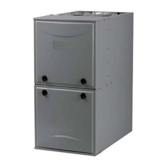
35" Tall, High Efficiency Condensing Gas Furnace
DANGER, WARNING, CAUTION, and NOTE
The
signal
words
CAUTION, and NOTE are used to identify levels of
hazard seriousness. The signal word DANGER is
only used on product labels to signify an immediate
hazard. The signal words WARNING, CAUTION,
and NOTE will be used on product labels and
throughout this manual and other manual that may
apply to the product.
DANGER − Immediate hazards which will result in
severe personal injury or death.
WARNING − Hazards or unsafe practices which
could result in severe personal injury or death.
CAUTION − Hazards or unsafe practices which
may result in minor personal injury or product or
property damage.
NOTE − Used to highlight suggestions which will
result in enhanced installation, reliability, or
operation.
TABLE OF CONTENTS
. . . . . . . . . . . . . . . . . . . . . . . . . . . . . . . . . . . . . . . .
. . . . . . . . . . . . . . . . . . . . . . . . . . . . . . .
. . . . . . . . . . . . . . . . . . . . . . . . . . . . . . . . . .
. . . . . . . . . . . . . . . . . . . . . . . . . . . . . . . . . . . . . .
. . . . . . . . . . . . . . . . . . . . . . . . . . . .
. . . . . . . . . . . . . . . . . . . . . . . . . . .
Printed in U.S.A.
SERVICE AND TECHNICAL
SUPPORT MANUAL
Single Stage, PSC Blower Motor
R9MSB (B Series)
Save this manual for future reference.
Safety Labeling and Signal Words
DANGER,
WARNING,
. . . .
. . . . . . . . . .
. . . . . . . . . . . . . . . . . . . .
. . . . . . . . . . . . . . . . . . .
. . . . . . . . . . . . . . . . . . . . .
. . . . . . .
. . . . . . . . .
. . . . . . . . . . . . . . . . . . . . . .
. . . . . . . .
. . . . . . . . . . . . . . . . . . . . . .
. . . . . . . .
. . . . . . . . .
. . . . . . . . .
. . . . . .
. . . . . . . . . . . . . . . . . . .
. . . . . . . . . . . . . . . . . . . . . .
. . . . . .
Signal Words in Manuals
The signal word WARNING is used throughout
this manual in the following manner:
WARNING
!
The signal word CAUTION is used throughout
this manual in the following manner:
CAUTION
!
Signal Words on Product Labeling
Signal words are used in combination with
colors and/or pictures or product labels.
Safety−alert symbol
When you see this symbol on the unit and in
instructions or manuals, be alert to the
potential for personal injury.
3
R9MSB0601716B
3
R9MSB0801716B
3
R9MSB1002120B
3
R9MSB1202420B
3
4
5
6
7
7
7
7
7
7
8
9
11
12
13
13
19
23
27
MODELS
Use of the AHRI Certified TM Mark indicates a
manufacturer's participation in the program.
For verification of certification for individual
products, go to www.ahridirectory.org .
440 04 6001 00
3/31/2014
Advertisement
Table of Contents

Related Manuals for International comfort products R9MSB0601716B


Summary of Contents for International comfort products R9MSB0601716B
-
Page 1: Table Of Contents
START−UP, ADJUSTMENT, AND SAFETY CHECK ..R9MSB0601716B GENERAL ........ - Page 2 SAFETY CONSIDERATIONS WARNING Improper ins t allation, adjus t ment, alteration, serv ic e, PERSONAL INJURY, AND/OR PROPERTY DAMAGE maintenance, or use can cause explosion, fire, electrical shock, HAZARD or other conditions which may cause death, personal injury, or Failure to carefully read and follow this warning could property damage.
-
Page 3: Start−Up, Adjustment, And Safety Check
START−UP, ADJUSTMENT, AND SAFETY Prime Condensate Trap with Water CHECK WARNING NOTICE CARBON MONOXIDE POISONING HAZARD Failure to follow these warnings could result in personal IMPORTANT INSTALLATION START−UP injury or death. PROCEDURES Failure to use a properly configured trap or NOT Failure to follow this procedure may result in a nuisance water-priming trap before operating furnace may allow smoke or odor complaint. -
Page 4: Check Inlet Gas Pressure
Tables have been provided in the furnace installation CAUTION instructions to match the required orifice to the manifold pressure to the heat content and specific gravity of the gas. To do this: FURNACE DAMAGE HAZARD 1. Obtain average yearly gas heat value (at installed Failure to follow this caution may result in reduced altitude) from local gas supplier. -
Page 5: Adjust Manifold Pressure
11. Turn gas supply manual shutoff valve to OFF i. Remove jumper R to W. position. j. Reinstall manifold pressure tap plug from gas valve. 12. Turn off furnace power supply. 2. Verify natural gas input rate by clocking meter. 13. -
Page 6: Adjust Temperature Rise
TWINNING AND/OR COMPONENT TEST BLOWER OFF-DELAY TERMINAL J2 JUMPER BLOWER OFF-DELAY HUMIDIFIER TERMINAL (24-VAC 0.5 AMP MAX.) 24-V THERMOSTAT TERMINALS TRANSFORMER 24-VAC CONNECTIONS TEST/TWIN 0.5 AMP@24VAC 3-AMP FUSE FUSE 3-AMP SEC-2 SEC-1 LED OPERATION & EAC-2 DIAGNOSTIC LIGHT PL1-LOW VOLTAGE MAIN HARNESS CONNECTOR 115-VAC(L2)NEUTRAL CONNECTIONS... -
Page 7: Adjust Blower Off Delay (Heat Mode)
3. Record amp. draw across terminals when furnace is WARNING in low heat and after blower starts. 4. Set heat anticipator on thermostat per thermostat instructions and install on sub-base or wall. ELECTRICAL OPERATION HAZARD 5. Install blower access door. Failure to follow this warning could result in personal Electronic thermostat: Set cycle rate for 3 cycles per hr. -
Page 8: Altitude Derate Multiplier For U.s.a
Table 2 – Altitude Derate Multiplier for U.S.A. THERMOSTAT SUBBASE ALTITUDE PERCENT DERATE TERMINALS WITH THERMOSTAT REMOVED MULTIPLIER (ANITICIPATOR, CLOCK, ETC., DERATE FACTOR* MUST BE OUT OF CIRCUIT.) 0–2000 0−610 1.00 HOOK-AROUND 2001–3000 610−914 4−6 0.95 AMMETER 3001–4000 914−1219 6−8 0.93 4001–5000 1219−1524... -
Page 9: Gas Rate (Cu Ft./Hr)
Table 3 – Gas Rate (CU ft./hr) SIZE OF TEST DIAL SIZE OF TEST DIAL SECONDS SECONDS FOR 1 REVOLUTION FOR 1 REVOLUTION 1 Cu Ft. 2 Cu Ft. 5 Cu Ft. 1 Cu Ft. 2 Cu Ft. 5 Cu Ft. 1800 1636 1500... - Page 10 338309-201 Rev. E A11602 Figure 5 − Service Label Information 440 04 6001 00 Specifications subject to change without notice.
-
Page 11: Orifice Size And Manifold Pressure
Table 4 – Orifice Size and Manifold Pressure (in. w.c.) for Gas Input Rate SINGLE-STAGE FURNACE (TABULATED DATA BASED ON 20,000 BTUH PER BURNER, DERATED 2%/1000 FT (305M) ABOVE SEA LEVEL) ALTITUDE RANGE HEAT VALUE 0.58 0.60 0.62 0.64 AT ALTITUDE Orifice Manifold Orifice... -
Page 12: Orifice Size And Manifold Pressure
Table 4 − Orifice Size and Manifold Pressure (in. w.c.) for Gas Input Rate (Cont.) SINGLE-STAGE FURNACE (TABULATED DATA BASED ON 20,000 BTUH PER BURNER, DERATED 2%/1000 FT (305M) ABOVE SEA LEVEL) ALTITUDE RANGE HEAT VALUE 0.58 0.60 0.62 0.64 AT ALTITUDE Orifice Manifold... -
Page 13: Service And Maintenance Procedures
SERVICE AND MAINTENANCE point of the switch is +/− 0.05 inches of water column from the nominal break point of the switch. The maximum make PROCEDURES point of the switch is 0.10 inches of water above the Untrained personnel can perform basic maintenance func- maximum break point of the switch tions such as cleaning and replacing air filters. - Page 14 5. The LED will flash the last stored fault code. Refer to 6. A component test sequence will follow. the Service Label (Figure 5) to interpret the LED. 7. Reinstall the Main/Control door. THE BLOWER IS LOCATED BELOW THE BURNER SECTION, AND CONDITIONED AIR IS DISCHARGED UPWARD.
- Page 15 Caution must be taken when manually closing this switch for Care and Maintenance service purposes. WARNING WARNING FIRE OR EXPLOSION HAZARD ELECTRICAL SHOCK HAZARD Failure to follow this warning could result in personal Failure to follow this warning could result in personal injury, death and/or property damage.
- Page 16 3. Check electrical connections for tightness and Blower Motor and Wheel Maintenance controls for proper operation each heating season. To ensure long life, economy, and high efficiency, clean Service as necessary. accumulated dirt and grease from blower wheel and motor 4.
- Page 17 8. Reassemble motor and blower wheel by reversing of light dirt or dust, they may be cleaned by using the items 7b through 7f. Ensure wheel is positioned for following procedure: proper rotation. NOTE: Use a back-up wrench on the gas valve to prevent 9.
- Page 18 NOTE: If manifold does not fit flush against the burner, do d. If replacement is required, remove the screw that secures the igniter on igniter bracket and remove the not force the manifold on the burner assembly. The burners igniter. are not fully seated forward in the burner assembly.
-
Page 19: Cleaning Heat Exchangers
6. Disconnect the condensate trap relief hose from Primary Heat Exchangers collector box port and condensate trap. If the heat exchangers get an accumulation of light dirt or NOTE: If condensate has a heat pad attached to the trap, dust on the inside, they may be cleaned by the following procedure: trace the wires for the pad back to the connection point and NOTE: If the heat exchangers get a heavy accumulation of... - Page 20 should be clear blue, almost transparent. (See 9. Remove the middle unused rubber plug from the port Figure 12.) on the collector box opposite the condensate trap. See Figure 10. 12. Check for gas leaks. 10. Repeat Steps 5 through 8. WARNING 11.
- Page 21 Burner Flame Burner Manifold A11461 Figure 12 − Burner Flame A11273 Figure 11 − Cleaning Heat Exchanger Cell GROMMET MOTOR SHAFT FLAT MOTOR ARM SCREW SET SCREW MOTOR WHEEL HUB SEE DETAIL SCREW LOCATION BLO HSG ASSY BRACKET BRACKET ENGAGEMENT DETAIL CUTOFF, BLOWER WHEEL, BLOWER...
- Page 22 IGNITER BURNER SUPT. ASSY BRACKET, IGNITER BURNER ASSY FLAME ROLLOUT SWITCH FLAME SENSOR (BELOW BURNER) A11403 Figure 14 − Burner Assembly 440 04 6001 00 Specifications subject to change without notice.
-
Page 23: Sequence Of Operation
SEQUENCE OF OPERATION EAC−1 is energized and remains energized as long as the blower motor BLWM is energized. NOTE: Furnace control must be grounded for proper f. Blower−Off Delay− When the thermostat is operation or control will lock out. Control is grounded satisfied, the R−to−W circuit is opened, de−... - Page 24 A12421 Figure 15 − Troubleshooting Guide 440 04 6001 00 Specifications subject to change without notice.
- Page 25 A11440 Troubleshooting Guide (Cont) Specifications subject to change without notice. 440 04 6001 00...
- Page 26 339236−2 Rev A Figure 16 − Wiring Diagram 440 04 6001 00 Specifications subject to change without notice.
-
Page 27: Parts Replacement Information Guide
SALES (MAJOR) REVISION DIGIT ENGINEERING (MINOR) REVISION DIGIT Have available the product/model number and the serial number located on the unit rating plate to ensure correct replacement parts. Copyright 2014 International Comfort Products Specifications subject to change without notice. 440 04 6001 00...