Table of Contents
Advertisement
Quick Links
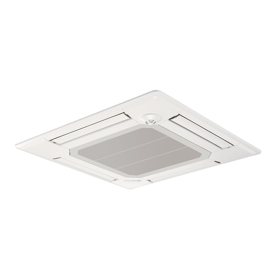
SPLIT-SYSTEM HEAT PUMP
SERVICE MANUAL
Indoor unit
[Model Name]
PLA-A12EA7
PLA-A18EA7
PLA-A24EA7
PLA-A30EA7
PLA-A36EA7
PLA-A42EA7
Grille model
[Model Name]
PLP-40EAEU
PLP-41EAEU
Model name
indication for
MAIN UNIT
INDOOR UNIT
ON/OFF
TEMP
IR WIRELESS REMOTE
CONTROLLER
(Option)
[Service Ref.]
PLA-A12EA7
PLA-A18EA7
PLA-A24EA7
PLA-A30EA7
PLA-A36EA7
PLA-A42EA7
Model name
indication for GRILLE
ON
RETURN SELECT
MENU
HOLD
OFF
WIRED REMOTE
CONTROLLER
(Option)
December 2019
No. OCH640
REVISED EDITION-D
Revision:
• Some descriptions have
been modified
in REVISED EDITION-D.
OCH640 REVISED EDITION-C
is void.
CONTENTS
1. REFERENCE MANUAL ........................ 2
2. SAFETY PRECAUTION ........................ 3
3. PARTS NAMES AND FUNCTIONS ...... 5
4. SPECIFICATIONS ............................... 13
5. NOISE CRITERION CURVES ............. 15
6. OUTLINES AND DIMENSIONS ............ 17
7. WIRING DIAGRAM ............................. 18
8. REFRIGERANT SYSTEM DIAGRAM ...... 19
9. TROUBLESHOOTING ........................ 20
10. FUNCTION SETTING ......................... 34
11. SPECIAL FUNCTION .......................... 35
12. DISASSEMBLY PROCEDURE ........... 39
PARTS CATALOG (OCB640)
Advertisement
Table of Contents

Related Manuals for Mitsubishi Electric Mr. Slim PLA-A12EA7


Summary of Contents for Mitsubishi Electric Mr. Slim PLA-A12EA7
-
Page 1: Table Of Contents
SPLIT-SYSTEM HEAT PUMP December 2019 No. OCH640 REVISED EDITION-D SERVICE MANUAL Indoor unit [Model Name] [Service Ref.] Revision: PLA-A12EA7 PLA-A12EA7 • Some descriptions have been modified PLA-A18EA7 PLA-A18EA7 in REVISED EDITION-D. PLA-A24EA7 OCH640 REVISED EDITION-C PLA-A24EA7 is void. PLA-A30EA7 PLA-A30EA7 PLA-A36EA7 PLA-A36EA7 PLA-A42EA7... -
Page 2: Reference Manual
REFERENCE MANUAL OUTDOOR UNIT SERVICE MANUAL Model Name Service Ref. Service Manual No. MXZ-2B20NA MXZ-2B20NA-2 OBH560 MXZ-3C24/30NA2, MXZ-4C36NA2 MXZ-3C24/30NA2-U1, MXZ-4C36NA2-U1 OBB560 MXZ-2C20NAHZ2, MXZ-2C24NAHZ2 MXZ-2C20NAHZ2-U1, MXZ-2C24NAHZ2-U1 OBH702 MXZ-2C30NAHZ2, MXZ-5C42NA2 MXZ-2C30NAHZ2-U1, MXZ-5C42NA2-U1 OBB702 MXZ-4C36NAHZ, MXZ-5C42NAHZ MXZ-4C36NAHZ, MXZ-5C42NAHZ OCH573 MXZ-8C48NAHZ, MXZ-8C48NA MXZ-8C48NAHZ, MXZ-8C48NA OCB573 MXZ-8C60NA MXZ-8C60NA... -
Page 3: Safety Precaution
SAFETY PRECAUTION 2-1. ALWAYS OBSERVE FOR SAFETY Before obtaining access to terminal, all supply circuits must be disconnected. 2-2. CAUTIONS RELATED TO NEW REFRIGERANT Cautions for units utilising refrigerant R410A Use the following tools specifically designed for Use new refrigerant pipes. use with R410A refrigerant. - Page 4 [1] Cautions for service (1) Perform service after recovering the refrigerant left in the unit completely. (2) Do not release refrigerant in the air. (3) After completing service, charge the cycle with specified amount of refrigerant. (4) When performing service, install a filter drier simultaneously. Be sure to use a filter drier for new refrigerant.
-
Page 5: Parts Names And Functions
PARTS NAMES AND FUNCTIONS 3-1. INDOOR UNIT Drain pipe Air outlet Liquid pipe Gas pipe i-See sensor (option) Filter Vane Air intake (Intake grille) OCH640D... - Page 6 3-2. Wired Remote Controller <PAR-40MAA> Controller interface The functions of the function buttons change depending on the screen. Refer to the button function guide that appears at the bottom of the LCD for the functions they serve on a given screen. When the system is centrally controlled, the button function guide that corresponds to the locked button will not appear.
- Page 7 Display The main display can be displayed in two different modes: “Full” and “Basic”. The initial setting is “Full”. To switch to the “Basic” mode, change the setting on the Main display setting. (Refer to operation manual included with remote controller.) <Full mode>...
- Page 8 Main menu Press the button. MENU Move the cursor to the desired item with the buttons, and press the button. SELECT Operation Vane · Louver · Vent. (Lossnay) High power Comfort Manual vane angle 3D i-See sensor Timer menu Timer ON/OFF timer Auto-OFF timer Weekly timer...
- Page 9 Continue from the previous page. Maintenance menu Error information Filter information Cleaning Auto descending panel Descending operation Descending adjustment Service menu Test run menu Test run Drain pump test run Maintenance information Model name input Serial No. input Dealer information input Initialize maintenance info.
- Page 10 Main menu list Main Setting and display items Setting details menu Operation Vane · Louver · Vent. Use to set the vane angle. (Lossnay) • Select a desired vane setting from 5 different settings. Use to turn ON/OFF the louver. •...
- Page 11 Setting and display Main menu Setting details items Initial Basic Main/Sub When connecting 2 remote controllers, one of them needs to be designated as setting setting a sub controller. Clock Use to set the current time. Daylight Set the daylight saving time. saving time Administrator The administrator password is required to make the settings for the following...
- Page 12 3-3. IR wireless remote controller (Option) display CHECK TEST RUN CHECK and TEST RUN display indicate that the unit is being checked or test-run. display MODEL SELECT Blinks when model is selected. display Lights up while the signal is transmitted to the indoor unit when the button is pressed.
-
Page 13: Specifications
SPECIFICATIONS Service Ref. PLA-A12EA7 Power supply (phase, cycle, voltage) Single phase, 60 Hz, 208/230 V Max. Fuse Size Min Circuit Ampacity PLP-40EAEU: Munsell 6.4Y 8.9/0.4 External finish (Panel) PLP-41EAEU: Munsell 1.0Y 9.2/0.2 Heat exchanger Plate fin coil Fan (drive) × No. Turbo fan (direct) ×... - Page 14 Service Ref. PLA-A30EA7 Power supply (phase, cycle, voltage) Single phase, 60 Hz, 208/230 V Max. Fuse Size Min Circuit Ampacity PLP-40EAEU: Munsell 6.4Y 8.9/0.4 External finish (Panel) PLP-41EAEU: Munsell 1.0Y 9.2/0.2 Heat exchanger Plate fin coil Fan (drive) × No. Turbo fan (direct) ×...
-
Page 15: Noise Criterion Curves
NOISE CRITERION CURVES PLA-A12EA7 PLA-A18EA7 NOTCH SPL(dB) LINE NOTCH SPL(dB) LINE High High Medium1 Medium1 Medium2 Medium2 NC-70 NC-70 NC-60 NC-60 NC-50 NC-50 NC-40 NC-40 NC-30 NC-30 APPROXIMATE APPROXIMATE THRESHOLD OF THRESHOLD OF HEARING FOR HEARING FOR NC-20 NC-20 CONTINUOUS CONTINUOUS NOISE NOISE... - Page 16 PLA-A36EA7 PLA-A42EA7 NOTCH SPL(dB) LINE NOTCH SPL(dB) LINE High High Medium1 Medium1 Medium2 Medium2 NC-70 NC-70 NC-60 NC-60 NC-50 NC-50 NC-40 NC-40 NC-30 NC-30 APPROXIMATE APPROXIMATE THRESHOLD OF THRESHOLD OF HEARING FOR HEARING FOR NC-20 NC-20 CONTINUOUS CONTINUOUS NOISE NOISE 1000 2000 4000...
-
Page 17: Outlines And Dimensions
OUTLINES AND DIMENSIONS PLA-A12EA7 PLA-A18EA7 PLA-A24EA7 PLA-A30EA7 PLA-A36EA7 PLA-A42EA7 Unit: inch (mm) OCH640D... -
Page 18: Wiring Diagram
WIRING DIAGRAM PLA-A12EA7 PLA-A18EA7 PLA-A24EA7 PLA-A30EA7 PLA-A36EA7 PLA-A42EA7 OCH640D... -
Page 19: Refrigerant System Diagram
REFRIGERANT SYSTEM DIAGRAM PLA-A12EA7 PLA-A18EA7 PLA-A24EA7 PLA-A30EA7 PLA-A36EA7 PLA-A42EA7 Strainer (#50) Heat exchanger Refrigerant GAS pipe connection (Flare) Condenser/evaporator temperature thermistor (TH5) Refrigerant flow in cooling Refrigerant flow in heating Refrigerant LIQUID pipe connection (Flare) Pipe temperature thermistor/liquid (TH2) Room temperature thermistor (TH1) Strainer (#50) Distributor... -
Page 20: Troubleshooting
TROUBLESHOOTING 9-1. TROUBLESHOOTING <Check code displayed by self-diagnosis and actions to be taken for service (summary)> Present and past check codes are logged, and they can be displayed on the wired remote controller and control board of out- door unit. Actions to be taken for service, which depends on whether or not the trouble is reoccurring in the field, are summa- rized in the table below. - Page 21 9-2. MALFUNCTION-DIAGNOSIS METHOD BY REMOTE CONTROLLER <In case of trouble during operation> When a malfunction occurs to air conditioner, both indoor unit and outdoor unit will stop and operation lamp blinks to inform unusual stop. < Malfunction-diagnosis method at maintenance service> ■IR wireless remote controller [Procedure] 1.
- Page 22 • Refer to the following tables for details on the check codes. [Output pattern A] Beeper sounds Beep Beep Beep Beep Beep Beep Beep OPERATION · · · Repeated INDICATOR lamp blink pattern Approx. 2.5 s 0.5 s 0.5 s 0.5 s Approx.
- Page 23 • On IR wireless remote controller The continuous buzzer sounds from receiving section of indoor unit. Blink of operation lamp • On wired remote controller 1 Check code displayed in the LCD. (Refer to the previous page, 1 check code.) •...
- Page 24 Note: Errors to be detected in outdoor unit, such as codes starting with F, U or E (excluding E0 to E7), 9-3. SELF-DIAGNOSIS ACTION TABLE are not covered in this document. Please refer to the outdoor unit service manual for the details. Check code Abnormal point and detection method Cause...
- Page 25 Check code Abnormal point and detection method Cause Countermeasure Freezing/overheating protection is work- (Cooling or drying mode) (Cooling or drying mode) 1 Clogged filter (reduced airflow) 1 Check clogs of the filter. 1 Freezing protection (Cooling mode) 2 Short cycle of air path 2 Remove shields.
- Page 26 Check code Abnormal point and detection method Cause Countermeasure Condenser/evaporator temperature ther- 1 Defective thermistor 1–3 Check resistance value of thermistor. For characteristics, refer to (P1). mistor (TH5) characteristics 2 Check contact failure of connector (CN44) 1 The unit is in 3-minute resume protec- 2 Contact failure of connector on the indoor controller board.
- Page 27 Check code Abnormal point and detection method Cause Countermeasure Remote controller transmission 1 2 remote controllers are set as 1 Set a remote controller to main, and the error(E3)/signal receiving error(E5) “main.” other to sub. 1 Abnormal if remote controller could not (In case of 2 remote con- find blank of transmission path for 6 sec- trollers)
- Page 28 9-4. TROUBLESHOOTING BY INFERIOR PHENOMENA Note: Refer to the manual of outdoor unit for the detail of remote controller. Phenomena Cause Countermeasure (1)Upward/downward vane 1 The vane is not downward during defrost- 1 Normal operation (The vane is set to hori- performance failure ing and heat preparation and when the zontal regardless of remote control.)
- Page 29 9-5. EMERGENCY OPERATION 9-5-1. When IR wireless remote controller troubles or its battery is exhausted When the remote controller cannot be used When the batteries of the remote controller run out or the remote control- ler malfunctions, the emergency operation can be done using the emer- gency buttons on the grille.
- Page 30 9-6. HOW TO CHECK THE PARTS PLA-A12EA7 PLA-A18EA7 PLA-A24EA7 PLA-A30EA7 PLA-A36EA7 PLA-A42EA7 Parts name Check points Room temperature Disconnect the connector then measure the resistance with a tester. thermistor (TH1) (At the ambient temperature of 50 to 86˚F [10 to 30˚C]) Pipe temperature thermistor/liquid(TH2) Refer to “9-6-1.
- Page 31 9-6-1. Thermistor <Thermistor characteristic graph> <Thermistor for lower temperature> Room temperature thermistor(TH1) Thermistor for Pipe temperature thermistor/liquid(TH2) lower temperature Condenser/evaporator temperature thermistor(TH5) Thermistor R =15 k" ± 3% Fixed number of B=3480 ± 2% t(:)Rt=15exp { 3480( 273+t T(˚F)Rt=15exp { 3480( T-32 273+ 32˚F...
- Page 32 9-7. TEST POINT DIAGRAM Indoor controller board PLA-A12EA7 PLA-A18EA7 PLA-A24EA7 PLA-A30EA7 PLA-A36EA7 PLA-A42EA7 CN5Y Vane motor (MV) Connect to wired remote controller i-See sensor motor (MT) 12 V pulse output 10.4–14.6 V DC 12 V pulse output Model selection CN90 Connect to the wireless J41, J42 remote controller board (CNB)
- Page 33 9-8. FUNCTIONS OF DIP SWITCH AND JUMPER WIRE Each function is controlled by the DIP switch and the jumper wire on indoor controller board. PLA-A12EA7 PLA-A18EA7 PLA-A24EA7 PLA-A30EA7 PLA-A36EA7 PLA-A42EA7 ■ The black square ( ) indicates a switch position. Jumper wire ( : Short : Open)
-
Page 34: Function Setting
FUNCTION SETTING 10-1. UNIT FUNCTION SETTING BY THE REMOTE CONTROLLER Each function can be set as necessary using the remote controller. The setting of function for each unit can only be done by the remote controller. (1) Functions available when setting the unit number to 00 Refer to the service manual that comes with each outdoor unit. -
Page 35: Special Function
SPECIAL FUNCTION 11-1. ROTATION FUNCTION (AND BACK-UP FUNCTION, 2ND STAGE CUT-IN FUNCTION) 11-1-1. Operation (1) Rotation function (and Back-up function) Outline of functions • Main and sub unit operate alternately according to the interval of rotation setting. Note: Main and sub unit should be set by refrigerant address. (Outdoor DIP switch setting) Refrigerant address "00"... - Page 36 • System constraint · This function is available only in cooling mode. Ex.) Set temp. by R/C = 68°F [20:] [2nd stage cut-in function]··· Request code number "322–324" Set point = 79°F [26:] When request code number is “323”. Room temp. ] Set point Room temp.
- Page 37 (2) How to send a request code Press the [ ] button. Main Main menu Select "Service" with the and press the [SELECT] button. Service RETURN SELECT MENU HOLD Enter the current maintenance password (4 numerical digits). • Move cursor to the digit you want to change with the button.
- Page 38 11-2. BACK-UP HEATING FUNCTION 11-2-1. Operation The back-up heater turns ON when both of the following conditions have been satisfied: A) When the room temperature has not risen after the heater ON delay time has passed. Note: The heater ON delay time starts when the condition of “set temperature − room temperature > 1°F [0.5:]” has been satisfied. B) Set temperature −...
-
Page 39: Disassembly Procedure
DISASSEMBLY PROCEDURE PLA-A12EA7 PLA-A18EA7 PLA-A24EA7 PLA-A30EA7 PLA-A36EA7 PLA-A42EA7 Be careful when removing heavy parts. OPERATING PROCEDURE PHOTOS/FIGURES 1. Removing the filter Figure 1 Knob Air intake grille (1) Slide the knob of air intake grille toward the arrow to open the air intake grille. (See Figure 1.) Grille (2) Pull down the lever of the air intake grille to remove the filter. - Page 40 OPERATING PROCEDURE PHOTOS/FIGURES 4. Removing the room temperature thermistor (TH1) Photo 3 Thermistor (TH1) (1) Remove the electrical box cover. (See Photo 1 and 2.) Electrical box (2) Disconnect the connector CN20 (Red) from the indoor Indoor controller controller board. CN20 board (3) Remove the room temperature thermistor with its holder.
- Page 41 Be careful when removing heavy parts. OPERATING PROCEDURE PHOTOS/FIGURES Photo 5 Bell mouth fixing screws 6. Removing the electrical box (1) Remove the electrical box cover (See Photo 1 and 2.) and the connectors (Refer to procedure 5.). (2) Remove the electrical box fixing screws (M5 × 10: 2 screws).
- Page 42 OPERATING PROCEDURE PHOTOS/FIGURES Nuts and washers 8. Removing the fan motor (MF) Photo 9 Rubber mounts (1) Remove the turbo fan. (See Photo 6 and refer to procedure 7.) (2) Remove the lead cover (tapping screw 4×10: 2 screws). (See Photo 9.) (3) Loosen the 2 clamps.
- Page 43 OPERATING PROCEDURE PHOTOS/FIGURES 10. Removing the drain pan Photo 12 (1) Remove the electrical box. (See photo 3 and refer to 6.) (2) Remove the bell mouth (tapping screw 4×10 : 2 screws). (See Photo 5.) Drain pan (3) Remove the drain pan (screw M5×10: 4 screws). Drain pan Drain pan fixing screws...
- Page 44 OPERATING PROCEDURE PHOTOS/FIGURES 12. Removing the drain pump (DP) Photo 14 (1) Remove the drain pan. (Refer to procedure 10.) (2) Cut the hose band and remove the hose. (3) Loosen the clamp of the drain pump. (4) Remove the drain pump (tapping screw 4×10: 2 screws/2 Drain pump hooks).
- Page 45 OPERATING PROCEDURE PHOTOS/FIGURES 14. Removing the heat exchanger Photo 16 (1) Remove the drain pan. (Refer to procedure 10.) Coil support fixing screw (2) Remove the piping cover (tapping screw 4×10: 3 Heat exchanger fixing screws screws). (3) Remove the coil plate (tapping screw 4×10: 2 screws). Coil support (4) Remove the heat exchanger fixing screws (tapping screw 4×10: 2 screws).
- Page 46 HEAD OFFICE: TOKYO BUILDING, 2-7-3, MARUNOUCHI, CHIYODA-KU, TOKYO 100-8310, JAPAN CCopyright 2016 MITSUBISHI ELECTRIC CORPORATION Issued: Dec. 2019 No.OCH640 REVISED EDITION-D Issued: Sep. 2018 No.OCH640 REVISED EDITION-C Issued: May 2018 No.OCH640 REVISED EDITION-B Issued: Mar. 2018 No.OCH640 REVISED EDITION-A Published: Oct. 2016 No.OCH640 Made in Japan Specifications are subject to change without notice.