Table of Contents
Advertisement
Quick Links
Advertisement
Table of Contents
Troubleshooting

Summary of Contents for NCM NCM-1550-EM30
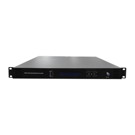
- Page 1 NCM-1550-EM30 (1550nm Externally Modulated Optical Transmitter) Operating Manual...
-
Page 2: Table Of Contents
NCM-1550-EM30 (1550nm externally modulated optical transmitter) operating manual Table of Contents Table of Contents ...................... - 1 - Safety Instruction ...................... - 2 - 1. Overview....................... - 3 - 1.1 About This Manual ..................- 3 - 1.2 Product Description ..................- 3 - 1.3 Product Applications .................. -
Page 3: Safety Instruction
NCM-1550-EM30 (1550nm externally modulated optical transmitter) operating manual 5.5 WEB Network Management ..............- 23 - 6. Maintenance and Troubleshooting..............- 25 - 6.1 Cleaning Fiber Optic Connectors............... - 25 - 6.1.1 Cleaning Patch Cord or Pigtail Fiber Optical Connectors ....- 25 - 6.2 Troubleshooting .................. -
Page 4: Overview
• Chapter 2 describes the complete technical specifications of NCM-1550-EM30. • Chapter 3 describes the front/rear panel interfaces and menu system. • Chapter 4 tells you how to install NCM-1550-EM30 series externally modulated optical transmitter. • Chapter 5 tells you the communication setting of NCM-1550-EM30. -
Page 5: Product Applications
Causing optical power fluctuation, generates large noise, and seriously deteriorates the system carrier to noise ratio (CNR). To improve the SBS threshold, NCM-1550-EM30 series optical transmitter adopts SBS control technology which is independent researched and developed by ourselves. The threshold value can be set up to 19dBm. -
Page 6: Technique Parameters
NCM-1550-EM30 (1550nm externally modulated optical transmitter) operating manual 2. Technique Parameters 2.1 Optical Parameters Item Unit Value ~ Optical Wavelength 1545 1560 (or specified by the user) Side-mode Suppression ratio >30 Relative Intensity Noise dB/Hz <-160 Wavelength Adjustment +/-50GHz Range... -
Page 7: Test Condition
NCM-1550-EM30 (1550nm externally modulated optical transmitter) operating manual 2.3 Test Condition First Second Second First stage paragraph stage paragraph EDFA (dBm) fiber length EDFA fiber length Tx/Rx 0dBm 13.5 Link 1 35km 0dBm 13.5 Link 2 16dBm 65km 0dBm Link 3... -
Page 8: Panel Interface And Menu System Description
NCM-1550-EM30 (1550nm externally modulated optical transmitter) operating manual 3. Panel Interface and Menu System Description 3.1 Front Panel RF modulation degree Power indicator AGC indicator indicator Laser indicator ESC key UP key DOWN key Enter key RF input port (or on the... -
Page 9: Rear Panel
NCM-1550-EM30 (1550nm externally modulated optical transmitter) operating manual 3.2 Rear Panel Ground stud Power module RF input port (or on the front RS232 interface LAN interface panel, optional) Optical output interface A (or Optical output interface B (or on the front panel, optional) on the front panel, optional) 3.3 Power Module... -
Page 10: Power Module
NCM-1550-EM30 (1550nm externally modulated optical transmitter) operating manual 3.3.2 48V Power Module Mounting screws + Positive terminal block - Negative terminal block 3.4 Menu Operation 3.4.1 Main Menu Displayed parameters Comments Boot display Menu one: Display parameters 1.Disp Parameters 2.Set Parameters... -
Page 11: Display Menu
NCM-1550-EM30 (1550nm externally modulated optical transmitter) operating manual 3.4.2 Display Menu Displayed Displayed Comments Comments parameters parameters Laser Output Output optical power +24V Read: +24V monitor voltage Laser current +12V monitor voltage Laser Bias +12V Read: RF CSO CSO monitor voltage... -
Page 12: Set Menu
NCM-1550-EM30 (1550nm externally modulated optical transmitter) operating manual 3.4.3 Set Menu Displayed parameters Comments Remarks Analong&digital full analog signal or analog Select RF input signal source Select RF input signal and digital mixed signal Digital full digital signal Set RF control mode... -
Page 13: Alarm Menu
NCM-1550-EM30 (1550nm externally modulated optical transmitter) operating manual 3.4.4 Alarm Menu The displayed alarm content Comment RF IN Status HIGH(LOW) The RF input signal is high (low) Laser Bias The laser bias current is high (low) HIGH(LOW) Laser TEC HIGH... -
Page 14: Frequency Adjust Itu In Dwdm
NCM-1550-EM30 (1550nm externally modulated optical transmitter) operating manual 3.4.7 Frequency Adjust ITU in DWDM To help DWDM applications, NCM-1550-EM30 can adjust optical wavelength. The adjustable range is ±100GHz, 50GHz stepping. The button on the front panel or the Ethernet interface will complete the adjustment. -
Page 15: Installing The Ncm-1550-Em30 Optical Transmitter
4.2 Precautions Heed the following precautions when working with the NCM-1550-EM30. Read the installation instructions before connecting the system to the power source. -
Page 16: Mounting Ncm-1550-Em30
Mounting the EM30 in the standard 19 inch equipment rack: 1. Place the equipment in the rack. 2. Use four screws fixed the mounting lug on the NCM-1550-EM30 front panel to the rack. 3. Reliably ground the equipment. The ground terminal is on the rear panel. -
Page 17: Connecting The Ethernet Cable
The Link LED is above the Ethernet port on the rear panel. 4.3.5 Connecting Power The NCM-1550-EM30 is available in an AC power model or DC power model. After mounting the NCM-1550-EM30 in a rack, follow the power connection procedure below for the model that you are installing. -
Page 18: Communication Setup
NCM-1550-EM30 (1550nm externally modulated optical transmitter) operating manual 5. Communication Setup 5.1 RS232 Communication Interface Description Adopt DB9 standard connector, the pin definitions as follow: 1: No Connect 2: TX 3: RX 4: No Connect 5: GND 6: No Connect... - Page 19 NCM-1550-EM30 (1550nm externally modulated optical transmitter) operating manual Then you input your connection name, such as “SNMP38400”,and choose the serial port to connect with your equipment. As follows: Press the “OK” button shows the configuration page of serial port. As follows: Change the serial port configuration to 38400-baud rate, 8 data bits, no parity bit, 1 stop bit, no data flow control, press the “OK”...
-
Page 20: Operating Parameters Configuration
NCM-1550-EM30 (1550nm externally modulated optical transmitter) operating manual 5.3 Operating Parameters Configuration Under the condition of power off, use the serial port lines to connect the RS232 port with the computer port. Open the Windows Hyper Terminal which you have set up. - Page 21 NCM-1550-EM30 (1550nm externally modulated optical transmitter) operating manual System supports the following commands: help List internal commands of the system; ethcfg Configure the Ethernet operating parameters; settrap Configure the aim host IP address of the SNMP Trap; community Configure the SNMP group name;...
- Page 22 NCM-1550-EM30 (1550nm externally modulated optical transmitter) operating manual and gateway. You can refer to the help information for its using. settrap This command shows or modifies the aim host IP address list of the SNMP Trap, IP address of 0.0.0.0 and 255.255.255.255 don’t exist. SNMP Trap does not send to these two addresses.
-
Page 23: Remote Monitoring: Snmp
NCM-1550-EM30 (1550nm externally modulated optical transmitter) operating manual 5.4 Remote Monitoring: SNMP LAN communication interface Adopt RJ45 standard connector, the pin definitions as follow: 1: TX+ 2: TX- 3: RX+ 4: No Connect 5: No Connect 6: RX- 7: No Connect 8: No Connect A: Green indicator flashing means that the LAN port is sending data. -
Page 24: Web Network Management
NCM-1550-EM30 (1550nm externally modulated optical transmitter) operating manual 5.5 WEB Network Management Open the IE browser, type the IP address and enter the interface as follows: Type the user name admin and the password 123456 (factory default), enter the following interface:... - Page 25 NCM-1550-EM30 (1550nm externally modulated optical transmitter) operating manual Click Set Paraments to enter Set Paraments interface as follows: The Item and Items columns list the parameters that can be changed, the Current column lists the present parameter values, the New column can select or type the new parameter values, and the Update column can update the parameters.
-
Page 26: Maintenance And Troubleshooting
We recommend that you clean all mating fiber connectors before connecting them to an optical transmitter. In addition, if you suspect that the optical connector of NCM-1550-EM30 may have been exposed to contamination (by a dirty fiber cable connector, for example), you should properly clean the NCM-1550-EM30 optical connector before connecting the optical fiber. -
Page 27: Troubleshooting
NCM-1550-EM30 (1550nm externally modulated optical transmitter) operating manual 6.2 Troubleshooting Should a problem occur, see if the symptoms are listed in Table 6-1. Table 6-1: Troubleshooting Solutions Indicator Fault Alarm menu content Solution status phenomenon The left (right) Plug in the left (right) power... -
Page 28: After-Sales Service Description
NCM-1550-EM30 (1550nm externally modulated optical transmitter) operating manual Reboot the equipment. If that OutPutPower Status HIGH The laser is off does not correct the problem, (LOW) contact Customer Service. Check the fiber connector. The optical output Follow the connector cleaning power is lower procedure (see Section 6.1).