Table of Contents
Advertisement
Quick Links
Upflow / Horizontal Left and Right Air Discharge
This is a safety alert symbol and should never be ignored. When you see this symbol on labels or in
manuals, be alert to the potential for personal injury or death.
Unit Dimensions ..........................................................2
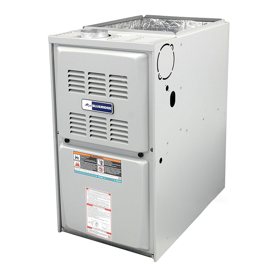
BG801UHE Gas Furnace ............................................3
Shipping and Packing List ...........................................3
Safety Information .......................................................3
General ........................................................................4
Combustion, Dilution & Ventilation Air .........................5
Filters .........................................................................10
Duct System ..............................................................10
Improper installation, adjustment, alteration, service
or maintenance can cause property damage, personal
injury or loss of life. Installation and service must be
performed by a licensed professional installer (or
equivalent), service agency or the gas supplier.
Manufactured By
Blue Summit LLC
8201 C National Turnpike
Louisville, KY 40214
507330-01B
INSTALLATION INSTRUCTIONS
BG801UHE
Warm Air Gas Furnace
This manual must be left with the homeowner for future reference.
Table of Contents
WARNING
Save these instructions for future reference
Venting.......................................................................11
Gas Piping .................................................................18
Electrical ....................................................................20
Unit Start-Up ..............................................................24
Blower Performance ..................................................29
Service.......................................................................31
Repair Parts List ........................................................32
As with any mechanical equipment, personal injury can
result from contact with sharp sheet metal edges. Be
careful when you handle this equipment.
*P507330-01B*
Issue 1809
CAUTION
(P) 507330-01B
Page 1 of 33
Advertisement
Table of Contents

Related Manuals for Alpine Blueridge BG801UHE

Summary of Contents for Alpine Blueridge BG801UHE
-
Page 1: Table Of Contents
INSTALLATION INSTRUCTIONS BG801UHE Warm Air Gas Furnace Upflow / Horizontal Left and Right Air Discharge This manual must be left with the homeowner for future reference. This is a safety alert symbol and should never be ignored. When you see this symbol on labels or in manuals, be alert to the potential for personal injury or death. -
Page 2: Unit Dimensions
Unit Dimensions NOTE -C*20 size units installed in upflow applications that 25 (635) require air volumes of 1800 cfm (850 L/s or greater must have one of the following: Single side return air with transition, to accommodate 20 x 25 x 1 in. (508 x 635 x 25 mm) air filter. Single side return air with optional RAB Return Air Base Bottom return air. -
Page 3: Bg801Uhe Gas Furnace
Clearances BG801UHE Gas Furnace Adequate clearance must be made around the air openings into the vestibule area. In order to ensure proper unit The BG801UHE gas furnace is shipped ready for operation, combustion and ventilation air supply must be installation in the upflow or horizontal right position (for provided according to the current National Fuel Gas Code. -
Page 4: General
Furnace must be installed as a two pipe system Heating Unit Installed Parallel to Air Handler Unit and one hundred percent (100%) outdoor air must be provided for combustion air requirements during construction. A room thermostat must control the furnace. The use of fixed jumpers that will provide continuous heating is prohibited. -
Page 5: Combustion, Dilution & Ventilation Air
In addition to the requirements outlined previously, the All gas fired appliances require air for the combustion following general recommendations must be considered process. If sufficient combustion air is not available, the when installing one of these furnaces: furnace or other appliances will operate inefficiently and unsafely. - Page 6 for combustion if the structure does not provide enough air (64516 mm2). One opening shall be within 12 inches (305 by infiltration. If the furnace is located in a building of tight mm) of the top of the enclosure and one opening within 12 construction with weather stripping and caulking around inches (305 mm) of the bottom.
- Page 7 Setting Equipment WARNING Do not install the furnace on its front or its back. Do not connect the return air ducts to the back of the furnace. Doing so will adversely affect the operation of the safety control devices, which could result in personal injury or death.
- Page 8 Upflow Applications Single side return air with optional return airbase. See Figure 12. Allow for clearances to combustible materials as indicated on the unit nameplate. Minimum clearances for closet or Bottom return air. alcove installations are shown in Figure 7. Return air from both sides.
- Page 9 This furnace may be installed in either an attic or a crawl space. Either suspend the furnace from roof rafters or floor joists, as shown in Figure 10, or install the furnace on a platform, as shown in Figure 13. Type of Vent Type C Type B...
-
Page 10: Filters
NOTE: Heavy gauge perforated sheet metal straps may be used to suspend the unit from roof rafters or ceiling WARNING joists. When straps are used to suspend the unit in this way, support must be provided for both the ends. The The inner blower panel must be securely in place when straps must not interfere with the plenum or exhaust the blower and burners are operating. -
Page 11: Venting
When return air is drawn from a room, a negative pressure is created in the room. If a gas appliance is operating in IMPORTANT a room with negative pressure, the flue products can be pulled back down the vent pipe and into the room. This The unit will not vent properly with the flue transition reverse flow of the flue gas may result in incomplete pointed down in the 6 o’clock position. - Page 12 • Cut combustion air inducer tubing from 9” to 5” to avoid • Cut combustion air inducer tubing from 9” to 7” to avoid interference with inducer motor. interference with inducer motor. • Disconnect pressure switch hose from barbed fitting on the pressure switch assembly.
- Page 13 WARNING Asphyxiation hazard. The exhaust vent for this furnace must be securely connected to the furnace flue transition at all times. Figure 21. Horizontal Right Position Side Vent Discharge These series units are classified as fan assisted Category I furnaces when vertically vented according to the latest Figure 22.
- Page 14 A fan assisted furnace may be commonly vented into an existing lined masonry chimney if the following conditions are met: • The chimney is currently serving at least one drafthood equipped appliance. • The vent connectors and chimney are sized according to the provided venting tables.
- Page 15 1. Vent diameter recommendations and maximum capacity). The horizontal length of the offset shall not allowable piping runs are found in the provided venting exceed 1-1/2 feet (.46 m) for each inch (25 mm) of tables. common vent diameter. In no case should the vent or vent connector diameter 10.
- Page 16 Capacity of Type B Double Wall Vents with Type B Double Wall Connectors Serving a Single Category I Appliance Vent and Connector Diameter - D (inches) Height Lateral 3 inch 4 inch 5 inch 6 inch Appliance Input Rating in Thousands of Btu per Hour (feet) (feet) NOTE: Single appliance venting configurations with zero lateral lengths are assumed to have no elbows in the vent system.
- Page 17 Vent Connector Capacity Type B Double Wall Vents with Type B Double Wall Connectors Serving Two or More Category I Appliances Vent and Connector Diameter - D (inches) Vent Connector 3 inch 4 inch 5 inch 6 inch Height Rise Appliance Input Rating in Thousands of Btu per Hour (feet) (feet)
-
Page 18: Gas Piping
Removal of the Furnace from Common Vent Follow the lighting instructions. Turn on the appliance that is being inspected. Adjust the thermostat so that In the event that an existing furnace is removed from the appliance operates continuously. a venting system commonly run with separate gas appliances, the venting system is likely to be too large to After the burners have operated for 5 minutes, test for properly vent the remaining attached appliances. - Page 19 Gas Pipe Capacity - FT³/HR (kL/HR) Internal Length of Pipe - feet (m) Nominal Iron Diameter Pipe Size - - inches inches (mm) (3.048) (6.096) (9.144) (12.192) (15.240) (18.288) (21.336) (24.384) (27.432) (30.480) (mm) .622 (12.7) (17.799) (4.96) (3.40) (2.75) (2.32) (2.07) (1.87)
-
Page 20: Electrical
The gas piping must not run in or through air ducts, clothes chutes, gas vents or chimneys, dumb waiters, or elevator shafts. The piping should be sloped 1/4 inch (6.4 mm) per 15 feet (4.57 m) upward toward the meter from the furnace. - Page 21 connected to this terminal with the neutral leg of the circuit being connected to one of the provided neutral terminals. If a humidifier rated at greater than one amp is connected to this terminal, it is necessary to use an external relay. One 24V “H”...
- Page 22 Figure 31. Wiring Diagram Page 22 of 33 Issue 1809 507330-01B...
- Page 23 -02 Integrated Control LED Codes Red LED Flash Code Diagnostic Codes / Status of Furnace LED Off No power to control or control hardware fault detected Heartbeat Control powered - displayed during all modes of operation if no errors are detected 1 Flash Reverse line voltage polarity 2 Flashes...
-
Page 24: Unit Start-Up
Terminal Designations 120 HUM Humidifier (120 VAC) LINE Input (120 VAC) XFMR Transformer (120 VAC) CIRC Indoor Blower (120 VAC) Electronic Air Cleaner (120 VAC) COOL Blower - Cooling Speed (24 VAC) HEAT Blower - Heating Speed (24 VAC) Blower - Fan Speed (24 VAC) PARK Dead terminals to park all speed taps NEUTRALS... - Page 25 BEFORE LIGHTING smell all around the appliance area Replace the upper access panel. for gas. Be sure to smell next to the floor because some 10. Turn on all electrical power to the unit. gas is heavier than air and will settle on the floor. 11.
- Page 26 Supply Pressure Measurement Gas is ignited, flame sensor proves the flame, and the combustion process continues. A threaded plug on the inlet side of the gas valve provides access to the supply pressure tap. Remove the threaded If flame is not detected after first ignition trial, the plug, install a field provided barbed fitting and connect a ignition control will repeat steps 3 and 4 four more manometer to measure supply pressure.
- Page 27 Proper Combustion Fan Control Furnace should operate a minimum 15 minutes with correct The fan on time of 45 seconds is not adjustable. The heat manifold pressure and gas flow rate before checking fan off delay (amount of time that the blower operates after combustion.
- Page 28 Constant Torque Motor Other Unit Adjustments These units are equipped with a constant torque ECM Primary and Secondary Limits motor. It has a DC motor coupled to an electronic control The primary limit is located on the heating compartment module,both contained in the same motor housing. The vestibule panel.
-
Page 29: Blower Performance
Blower Performance BG801UH070BE12 Performance (Less Filter) External Air Volume / Watts at Various Blower Speeds Static High Medium - High Medium Medium - Low Pressure watts watts watts watts watts in. w.c. 0.00 1415 1330 1215 1175 1075 0.10 1415 1295 1145 1130... - Page 30 Page 30 of 33 Issue 1809 507330-01B...
-
Page 31: Service
Filters Service Filters are installed external to the unit. Filters should be inspected monthly. Clean or replace the filters when necessary to ensure that the furnace operates properly. Replacement filters must be rated for high velocity airflow. WARNING Table 1 lists recommended filter sizes. ELECTRICAL SHOCK, FIRE, OR EXPLOSION HAZARD. -
Page 32: Repair Parts List
Figure 36. Burner Assembly Removal Repair Parts List The following repair parts are available through independent Blue Summit dealers. When ordering parts, include the complete furnace model number listed on the CSA International nameplate. All service must be performed by a licensed professional installer (or equivalent), service agency, or gas supplier. - Page 33 Requirements for Commonwealth of Massachusetts Modifications to NFPA-54, Chapter 10 INSPECTION. The state or local gas inspector of the side wall, horizontally vented, gas-fueled equipment Revise NFPA-54 section 10.8.3 to add the following shall not approve the installation unless, upon requirements: inspection, the inspector observes carbon monoxide For all side wall, horizontally vented, gas-fueled equipment...