Table of Contents
Advertisement
Advertisement
Table of Contents

Related Manuals for Navistar MaxxForce DT 9


Summary of Contents for Navistar MaxxForce DT 9
- Page 1 MaxxForce® DT, 9, and 10 Diesel Engines 2010 EPA Emission Compliant Model Year Truck and Derivative Vehicle Applications Engine Operation and Maintenance Manual © 2011 Navistar, Inc. All rights reserved. Form No. 1172040R1 Printed in the United States of America...
- Page 2 Form No. 1172040R1 Printed in the United States of America...
-
Page 3: Table Of Contents
TABLE OF CONTENTS FOREWORD..................1 SAFETY INFORMATION...............3 WARRANTY..................7 Federal Emission System Warranty ................7 Warranty Period. - Page 4 TABLE OF CONTENTS Engine Description..................17 Engine Features.
- Page 5 TABLE OF CONTENTS Warning Lights ....................37 Wait to Start Lamp .
- Page 6 TABLE OF CONTENTS Cold Weather Operation................. . .54 Cold Ambient Protection (CAP).
- Page 7 TABLE OF CONTENTS Engine Brake Lash..................87 Induction System.
- Page 8 Form No. 1172040R1 Printed in the United States of America...
-
Page 9: Foreword
This manual contains information needed to correctly operate illustration may not be exact. and maintain your engine as recommended by Navistar, Inc. Numerous illustrations, symbols and feature descriptions This manual includes necessary information and specifications are used to aid in understanding the meaning of the text. - Page 10 FOREWORD Form No. 1172040R1 Page 2 Printed in the United States of America...
-
Page 11: Safety Information
SAFETY INFORMATION Safety Information Safety Instructions Work Area This manual provides general and specific maintenance procedures essential for reliable engine operation and your • Keep work area clean, dry, and organized. safety. Since many variations in procedures, tools, and service •... - Page 12 SAFETY INFORMATION • Clear the area before starting the engine. 3. Type C — Electrical equipment Engine Batteries • The engine should be operated or serviced only by qualified • Always disconnect the main negative battery cable first. individuals. • Always connect the main negative battery cable last.
- Page 13 SAFETY INFORMATION • Check for frayed power cords before using power tools. Fluids Under Pressure • Use extreme caution when working on systems under pressure. • Follow approved procedures only. Fuel • Do not over fill the fuel tank. Over fill creates a fire hazard. •...
- Page 14 SAFETY INFORMATION Form No. 1172040R1 Page 6 Printed in the United States of America...
-
Page 15: Warranty
Warranty repairs should be completed in a reasonable time, not • Or if covered by any basic or extended warranty (if greater to exceed 30 days. Navistar may deny warranty coverage if than above) your vehicle or a part has failed due to abuse, neglect, improper maintenance or unapproved modifications. -
Page 16: Emergency Repairs
Aftermarket parts or service kits WARRANTY RIGHTS AND RESPONSIBILITIES • Non-defective parts replaced by an unauthorized service provider. Navistar assures that the emission warranty is being properly administered. If you have not received satisfactory service Form No. 1172040R1 Page 8... - Page 17 The address and phone number of each regional office is listed in your Vehicle Operator Manual. If additional assistance is required, contact the Manager of Customer Relations. Manager, Customer Relations Navistar, Inc. 4201 Winfield Road Warrenville, Illinois 60555 (Telephone 1-800-448-7825) Form No.
-
Page 18: California Emission System Warranty
Warranty repairs should be completed in a reasonable time, not Your medium-heavy duty diesel engine conforms to applicable to exceed 30 days. Navistar may deny you warranty coverage if California Air Resources Board regulations. This vehicle is your vehicle or a part has failed due to abuse, neglect, improper registered and certified for sale in California. -
Page 19: What Is Covered By Warranty
• Pulleys, belts and idlers replacement part. • Vacuum, temperature and time sensitive valves and Navistar will reimburse you for emergency repairs (including switches diagnostics) for the following: WHAT IS NOT COVERED BY WARRANTY • Replacement parts that do not exceed manufacturer’s suggested retail price. -
Page 20: Warranty Rights And Responsibilities
Vehicles with an altered or disconnected odometer or hourmeter when mileage or hours cannot be determined. WARRANTY RIGHTS AND RESPONSIBILITIES Navistar assures that the emission warranty is being properly administered. If you have not received satisfactory service or have questions regarding your warranty rights and responsibilities, contact the regional office for assistance. -
Page 21: Section 1 - Engine Systems
SECTION 1 – ENGINE SYSTEMS Engine Serial Number Engine Serial Number Examples MaxxForce® DT: 466HM2U3300001 MaxxForce® 9 and 10: 570HM2U3300001 Engine Serial Number Codes 466 – Engine displacement 570 – Engine displacement H – Diesel, turbocharged, Charge Air Cooler (CAC) and electronically controlled M2 –... -
Page 22: Engine Emission Label
SECTION 1 – ENGINE SYSTEMS Engine Emission Label The U.S. Environmental Protection Agency (EPA) exhaust emission label is attached on top of the valve cover. The EPA label typically includes the following: • Model year • Engine family, model, and displacement •... -
Page 23: Engine Specifications
SECTION 1 – ENGINE SYSTEMS Engine Specifications MaxxForce® DT, 9, and 10 Diesel Engines Engine Configuration 4 stroke, inline six cylinder diesel Advertised brake horsepower @ rpm See engine emission label Peak torque @ rpm See engine emission label Displacement •... - Page 24 SECTION 1 – ENGINE SYSTEMS Engine Specifications (cont.) MaxxForce® DT, 9, and 10 Diesel Engines Lube system capacity (including filter) 28 L (30 qts US) Lube system capacity (overhaul only, with filter) 32 L (34 qts US) Engine lubrication oil pressure at operating temperature with SAE 10W-30 oil •...
-
Page 25: Engine Description
SECTION 1 – ENGINE SYSTEMS Engine Specifications (cont.) Engine Description START lamp. When the lamp turns off, the engine can be started. MaxxForce® DT, 9, and 10 are inline six cylinder diesel engines Crankcase Assembly which have been designed for increased durability, reliability, and ease of maintenance. - Page 26 SECTION 1 – ENGINE SYSTEMS Engine Description (cont.) Crankshaft Electronic Control System The crankshaft has seven main bearings with fore and aft thrust An Engine Control Module (ECM) monitors and controls sensors, controlled at the rear bearing. One fractured cap connecting rod actuators, and valves to ensure maximum engine performance is attached at each crankshaft journal.
-
Page 27: Engine Features
SECTION 1 – ENGINE SYSTEMS Engine Features The low idle governor prevents engine rpm from dropping below a stable speed to prevent stalling when various loads are Aftertreatment System demanded on the engine. engine vehicle exhaust piping includes The high idle governor prevents engine rpm from going above a Aftertreatment System to capture soot and other particulates safe speed that would cause engine damage. - Page 28 SECTION 1 – ENGINE SYSTEMS Engine Features (cont.) Electronic Speedometer and Tachometer Fast Idle Advance The engine control system calibrates vehicle speed. Any new Fast idle advance increases engine idle speed for faster speed calibration information must be programmed with an EST. warm-up to operating temperature.
-
Page 29: Engine Optional Features
SECTION 1 – ENGINE SYSTEMS Engine Optional Features Engine Warning Protection System (EWPS) EWPS is designed to protect the engine from damage Air Compressor by monitoring critical engine data such as engine speed, An air compressor is available for applications that require air temperature, oil pressure and coolant levels. - Page 30 SECTION 1 – ENGINE SYSTEMS Engine Optional Features (cont.) In Cab Power Take-off (PTO) Control When control over engine speed is required from outside the vehicle’s cab, remote mounted switches must be used to turn on The in cab engine speed control feature, commonly referred to PTO engine speed control and select the desired engine speed.
- Page 31 SECTION 1 – ENGINE SYSTEMS Engine Optional Features (cont.) Service Interval The service interval feature is designed to provide a visual reminder to the operator that the engine oil change interval has expired and routine maintenance procedures should be performed. The term “interval”...
-
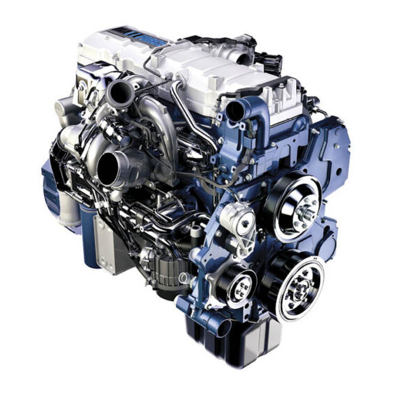
Page 32: Engine Component Locations
SECTION 1 – ENGINE SYSTEMS Engine Component Locations COMPONENT LOCATION - TOP Figure 3 Top Water outlet tube assembly Valve cover 13. Fuel filter assembly Interstage cooler inlet duct (245 HP and Exhaust emission label (location) 14. Electronic fuel pump (fuel strainer above) Air and Exhaust Gas Recirculation (EGR) location) -
Page 33: Component Location - Front
SECTION 1 – ENGINE SYSTEMS Engine Component Locations (cont.) COMPONENT LOCATION - FRONT Figure 4 Front High-pressure turbo outlet EGR valve 10. Water inlet elbow Water outlet tube assembly Oil level gauge 11. Water pump pulley Deaeration hose elbow Front cover 12. -
Page 34: Component Location - Intake Side
SECTION 1 – ENGINE SYSTEMS Engine Component Locations (cont.) COMPONENT LOCATION - INTAKE SIDE Figure 5 Intake side Electric fuel pump (fuel strainer location) Air and EGR mixer duct Oil Pan Fuel filter assembly Intake manifold 10. Power steering pump Oil level gauge Engine Control Module (ECM) 11. -
Page 35: Component Location - Exhaust Side
SECTION 1 – ENGINE SYSTEMS Engine Component Locations (cont.) COMPONENT LOCATION - EXHAUST SIDE Figure 6 Exhaust side Exhaust brake valve assembly Alternator bracket 14. Oil filter Low-pressure turbocharger Crankcase breather outlet tube 15. Low-pressure turbo oil drain tube High-pressure turbocharger 10. -
Page 36: Component Location - Rear
SECTION 1 – ENGINE SYSTEMS Engine Component Locations (cont.) COMPONENT LOCATION - REAR Figure 7 Rear Air and Exhaust Gas Recirculation (EGR) Turbo air inlet duct Flywheel mixer EGR crossover tube assembly Injector feed tube assembly Exhaust brake valve Rear engine mounting bracket (2) 10. -
Page 37: Section 2 - Requirements For Fuel, Engine Oil, And Coolant
SECTION 2 – REQUIREMENTS FOR FUEL, ENGINE OIL, AND COOLANT Fuel Ultra Low Sulfur Diesel (ULSD) fuel is required for MaxxForce® DT, 9, and 10 Diesel Engines used with advanced aftertreatment ULTRA LOW SULFUR DIESEL (ULSD) systems. The fuel should meet all the specifications of ASTM D975 standard (current year revision), including the EPA specification for sulfur content (0.0015 % mass or 15 ppm maximum). -
Page 38: Acceptable Fuel Blends
(D975-08a designates the 2008 revision of the standard.) perform satisfactorily in diesel engines. Contact your dealer Navistar, Inc. approves of blends up to B5, provided that the for recommendations for correct storage and maintenance two components satisfy current specifications. Quality biodiesel procedures. -
Page 39: Unsafe Practices
This creates a fire hazard and possible explosion. CAUTION: To prevent engine damage, do not mix propane with diesel fuel. Navistar will not honor warranty claims against engines that have used propane. Form No. 1172040R1... -
Page 40: Engine Oil
SECTION 2 – REQUIREMENTS FOR FUEL, ENGINE OIL, AND COOLANT Engine Oil NOTE: Mineral and synthetic oils are acceptable for use provided they meet the API category recommendations and ENGINE OIL QUALITY AND SERVICE CATEGORIES ambient temperature guidelines. API CJ-4 oils provide protection against the following: The American Petroleum Institute (API) defines engine oil quality by service categories that define oil performance measured in •... -
Page 41: Sae Oil Viscosity Grades And Temperature Ranges
SECTION 2 – REQUIREMENTS FOR FUEL, ENGINE OIL, AND COOLANT Engine Oil (cont.) SAE OIL VISCOSITY GRADES AND TEMPERATURE The Society of Automotive Engineers (SAE) defines oil viscosity RANGES (thickness) by grade. Colder temperatures require lower grade oils for correct flow during starting. Higher temperatures require higher grade oils for satisfactory lubrication. -
Page 42: Coolant
SECTION 2 – REQUIREMENTS FOR FUEL, ENGINE OIL, AND COOLANT Coolant Freeze Point Protection Levels Concentrate (ethylene glycol) and Water Mixtures COOLANT MIXTURES Concentrate and Water Freeze Point Protection Mixtures Engine coolant mixtures include water, glycol (ethylene or propylene), and inhibitors. Conventional and fully formulated 40% Concentrate and 60% -24.4 °C (-12 °F) coolants require regular testing of inhibitor levels to maintain... -
Page 43: Contamination Of Coolant
SECTION 2 – REQUIREMENTS FOR FUEL, ENGINE OIL, AND COOLANT Coolant (cont.) CONTAMINATION OF COOLANT The coolant color should indicate the condition of the coolant. • Coolant color should be a reddish orange (clear – not cloudy). • Coolant must not have floating debris or visible oil. Contamination of ELC with other coolant products will not be obvious. - Page 44 SECTION 2 – REQUIREMENTS FOR FUEL, ENGINE OIL, AND COOLANT Form No. 1172040R1 Page 36 Printed in the United States of America...
-
Page 45: Section 3 - Instruments, Indicators, And Switches
SECTION 3 – INSTRUMENTS, INDICATORS, AND SWITCHES Instrument Panel Gauge Cluster Wait to Start Lamp During engine starts and engine operation, gauges and indicator lamps should be checked periodically. Gauges may vary with vehicle applications. Warning and indicator lamps show conditions not indicated by the gauges. This manual does not describe indicator lamps for the drivetrain, chassis components, or cab interior. -
Page 46: Idle Shut Down Indicator
SECTION 3 – INSTRUMENTS, INDICATORS, AND SWITCHES Idle Shut Down Indicator Maintenance Lamp Figure 13 Maintenance lamp Figure 12 Idle shutdown indicator The Maintenance lamp will illuminate in conjunction with other warning lights or general text and warning messages. It may be The IDLE SHUTDOWN indicator will illuminate when the vehicle accompanied by an audible alarm to indicate an alert condition shutdown timer will turn the engine off in 30 seconds. -
Page 47: Warn Engine Lamp
SECTION 3 – INSTRUMENTS, INDICATORS, AND SWITCHES Warn Engine Lamp Stop Engine Lamp Figure 14 Warn engine lamp Figure 15 Stop engine lamp The warn engine lamp will illuminate by itself, or in conjunction with other warning lights or general text and warning messages, CAUTION: To prevent engine damage, shutdown engine to indicate an alert condition to the operator. -
Page 48: High Exhaust System Temperature (Hest) Lamp
SECTION 3 – INSTRUMENTS, INDICATORS, AND SWITCHES High Exhaust System Temperature (HEST) Lamp Diesel Particulate Filter (DPF) Indicator Figure 16 HEST lamp Figure 17 DPF indicator The DPF indicator operates at three different levels. WARNING: Exhaust components are operating under Level One normal conditions and exhaust gases are at extremely high temperatures. -
Page 49: Malfunction Indicator Lamp
SECTION 3 – INSTRUMENTS, INDICATORS, AND SWITCHES Diesel Particulate Filter (DPF) Indicator (cont.) Malfunction Indicator Lamp Level Two The DPF indicator will be flashing indicating the exhaust filter is full. The vehicle should be safely pulled off the roadway and parked. Start the Parked Regeneration process to prevent loss of engine power. -
Page 50: Typical Water Temperature Gauge
SECTION 3 – INSTRUMENTS, INDICATORS, AND SWITCHES Typical Water Temperature Gauge CAUTION: To prevent engine damage – do not operate engine above 112 °C (234 °F); this may cause internal damage. The indicator lamp will be activated at engine coolant temperatures above 109 °C (228 °F). -
Page 51: Oil Pressure Gauge
SECTION 3 – INSTRUMENTS, INDICATORS, AND SWITCHES Oil Pressure Gauge Lubrication Oil Pressure Lube Oil Pressure At normal operating temperature Low idle 214 kPa (31 psi) min. High idle 276 kPa (40 psi) CAUTION: To prevent engine damage, shut down engine immediately if the gauge fluctuates or drops below 276 kPa (40 psi) under load. -
Page 52: Oil Temperature Gauge
SECTION 3 – INSTRUMENTS, INDICATORS, AND SWITCHES Oil Temperature Gauge Figure 21 Oil temperature gauge The engine oil temperature gauge indicates the operating oil temperature of the engine. Form No. 1172040R1 Page 44 Printed in the United States of America... -
Page 53: Switches
SECTION 3 – INSTRUMENTS, INDICATORS, AND SWITCHES Switches ENGINE EXHAUST BRAKE ON/OFF TOGGLE SWITCH ENGINE BRAKE ON/OFF SWITCH Figure 23 Exhaust brake toggle switch Figure 22 Engine brake ON / OFF switch The exhaust brake toggle switch turns engine exhaust brake ON or OFF. -
Page 54: Air Cleaner Restriction Indicator
SECTION 3 – INSTRUMENTS, INDICATORS, AND SWITCHES Air Cleaner Restriction Indicator induction system or instrument panel depending on your specific application. Air restriction is resistance of airflow through the air cleaner. Air Restriction Indicator Calibration Accurate air restriction is measured at maximum airflow. •... -
Page 55: Section 4 - Engine Operation
SECTION 4 – ENGINE OPERATION Preoperation Checklist Figure 25 Oil level gauge (typical) GOVERNMENT REGULATION: Engine fluids (oil, fuel, and coolant) may be a hazard to human health and the environment. Handle all fluids and 2. Check for correct oil level. other contaminated materials (e.g. -
Page 56: Priming The Fuel System
SECTION 4 – ENGINE OPERATION Priming the Fuel System WARNING: To prevent personal injury or death, do not smoke and keep fuel away from open flames and sparks. CAUTION: To prevent engine damage, do not add fuel to the fuel filter header. this can contaminate the fuel. 1. - Page 57 SECTION 4 – ENGINE OPERATION Starting the Engine (cont.) the engine has push button starting, press and hold starter 8. Within 20 seconds after engine start, engine oil pressure button. should exceed 214 kPa (31 psi). 5. When the engine starts, release the ignition switch or starter 9.
-
Page 58: Emergency Starting
SECTION 4 – ENGINE OPERATION Emergency Starting WARNING: To prevent personal injury or death, always connect jumper cable for positive battery terminals WARNING: To prevent personal injury or death, do not first. use ether starting fluid to start engine. 4. Connect one end of the first jumper cable to the positive (+) terminal of the dead battery or to the positive (+) terminal of the jump start stud. -
Page 59: Operation
SECTION 4 – ENGINE OPERATION Operation High idle speed is a nonadjustable factory setting. The high idle setting depends on the application of the engine and has the SUGGESTED WARM UP TIME following ranges: MaxxForce® DT: 2600 rpm through 2770 rpm NOTE: Before applying a load or increasing speed above 1000 rpm, warm up engine for a minimum of 5 minutes at or below MaxxForce®... -
Page 60: Aftertreatment System
SECTION 4 – ENGINE OPERATION Operation (cont.) AFTERTREATMENT SYSTEM • See the “Safety Information” (page 3) section for safety precautions. engine vehicle exhaust piping includes A Preliminary Diesel Oxidation Catalyst (PDOC) and a DOC Aftertreatment System to capture soot and other particulates operates together to oxidize the injected fuel to increase the before they exit the exhaust pipe. -
Page 61: Engine Idle Shutdown Timer (California-Standard)
SECTION 4 – ENGINE OPERATION Operation (cont.) ENGINE IDLE SHUTDOWN TIMER (FEDERAL-OPTIONAL) (cont.) • Vehicle movement or a Vehicle Speed Sensor (VSS) fault is ENGINE IDLE SHUTDOWN TIMER detected. (CALIFORNIA-STANDARD) • Manual DPF Regeneration is enabled (Parked Regen). • Accelerator pedal movement or an Accelerator Pedal Sensor (APS) fault is detected. -
Page 62: Cold Weather Operation
SECTION 4 – ENGINE OPERATION Operation (cont.) ENGINE IDLE SHUTDOWN TIMER (CALIFORNIA-STANDARD) (cont.) Thirty seconds before engine shutdown, the IDLE SHUTDOWN • If the IST is enabled, the Cold Ambient Protection (CAP) will indicator illuminates. This continues until the engine shuts down not function. -
Page 63: Cold Ambient Protection (Cap)
SECTION 4 – ENGINE OPERATION Operation (cont.) COLD WEATHER OPERATION (cont.) • Correct coolant and cooling system level COLD AMBIENT PROTECTION (CAP) • Recommended oil grade CAP safeguards the engine from damage caused by prolonged idle at no load during cold weather. This feature should only be 2. -
Page 64: Hot Weather Operation
SECTION 4 – ENGINE OPERATION Operation (cont.) HOT WEATHER OPERATION ENGINE SHUTDOWN 1. Before operating the engine above 21 °C (70 °F), check or Before shutting down an engine that has reached operating service the following: temperature, idle the engine for 2 to 3 minutes, allowing the hottest engine components to dissipate some of their internal •... -
Page 65: Radiator Shuttle Enable (Rse)
SECTION 4 – ENGINE OPERATION Operation (cont.) ENGINE WARNING PROTECTION SYSTEM (EWPS) (cont.) The following optional features to this base system provide • ECT - Engine overheat warning added warning or protection. • EOP - Low engine oil pressure warning 2 - Way Warning (optional) •... -
Page 66: Road Speed Limiting (Rsl)
SECTION 4 – ENGINE OPERATION Operation (cont.) ROAD SPEED LIMITING (RSL) 4. When approaching a hill, press accelerator smoothly to start the upgrade at full power. Downshift to maintain maximum RSL is an optional feature that limits the top vehicle speed the vehicle speed. -
Page 67: Section 5 - Maintenance Schedule And Service Procedures
SECTION 5 – MAINTENANCE SCHEDULE AND SERVICE PROCEDURES NOTE: No maintenance is required on the Doser Injector, it is not a serviceable component. Failed parts should be replaced, not serviced. The Doser is warranted under base mechanical and or emission warranty. Maintenance Schedule MaxxForce®... - Page 68 SECTION 5 – MAINTENANCE SCHEDULE AND SERVICE PROCEDURES Maintenance Schedule (cont.) MaxxForce® DT, 9, and 10 Diesel Engines (cont.) Service operation interval - which ever comes first: kilometers/miles, months, years, hours, or liters/gallons of fuel Service Interval Service Operation See service procedures in this section for more information. 24,140 km (15,000 miles) Inspect belt, air intake piping, and clamps.
- Page 69 SECTION 5 – MAINTENANCE SCHEDULE AND SERVICE PROCEDURES Maintenance Schedule (cont.) MaxxForce® DT, 9, and 10 Diesel Engines (cont.) Service operation interval - which ever comes first: kilometers/miles, months, years, hours, or liters/gallons of fuel Service Interval Service Operation See service procedures in this section for more information. 290,000 - 322,000 km Measure crankcase pressure.
-
Page 70: Service Procedures
SECTION 5 – MAINTENANCE SCHEDULE AND SERVICE PROCEDURES Service Procedures Figure 27 Oil level gauge (typical) GOVERNMENT REGULATION: Engine fluids (oil, fuel, and coolant) may be a hazard to human health and the environment. Handle all fluids and CAUTION: To prevent engine damage do the following: other contaminated materials (e.g. -
Page 71: Coolant Level
SECTION 5 – MAINTENANCE SCHEDULE AND SERVICE PROCEDURES Service Procedures (cont.) COOLANT LEVEL NOTE: Never add ELC to the expansion tank. Only add ELC to the coolant tank. WARNING: To prevent personal injury or death, do the GOVERNMENT REGULATION: Engine fluids following when removing the radiator cap or coolant tank (oil, fuel, and coolant) may be a hazard to human cap:... - Page 72 SECTION 5 – MAINTENANCE SCHEDULE AND SERVICE PROCEDURES Service Procedures (cont.) COOLANT LEVEL (cont.) 5. Add ELC 50/50 Premix to the correct coolant level (between WARNING: To prevent personal injury or death, do the COLD MIN and COLD MAX marks). following when removing the radiator cap or coolant tank 6.
-
Page 73: Water Separator
SECTION 5 – MAINTENANCE SCHEDULE AND SERVICE PROCEDURES Service Procedures (cont.) WATER SEPARATOR Service Interval: Before Engine Operation GOVERNMENT REGULATION: Engine fluids (oil, fuel, and coolant) may be a hazard to human health and the environment. Handle all fluids and other contaminated materials (e.g. -
Page 74: Charge Air Cooler (Cac)
SECTION 5 – MAINTENANCE SCHEDULE AND SERVICE PROCEDURES Service Procedures (cont.) WATER SEPARATOR (cont.) 2. Put a suitable container under water drain valve or drain CHARGE AIR COOLER (CAC) hose. Service Interval: Before Engine Operation 3. Turn ignition switch to ON. This will start the electric fuel pump. -
Page 75: External Leakage
SECTION 5 – MAINTENANCE SCHEDULE AND SERVICE PROCEDURES Service Procedures (cont.) EXTERNAL LEAKAGE Service Interval: Before Engine Operation WARNING: To prevent personal injury or death, shut down engine, set parking brake, and block wheels before inspecting for external leakage. 1. Check for the following: •... -
Page 76: Air Cleaner Restriction
SECTION 5 – MAINTENANCE SCHEDULE AND SERVICE PROCEDURES Service Procedures (cont.) AIR CLEANER RESTRICTION same reading when the vehicle is driven under normal driving conditions. Service Interval: Before Engine Operation If the yellow position indicator has locked in the red zone, a new air filter should be installed to prevent low engine power or engine damage. -
Page 77: Engine Oil And Filter
SECTION 5 – MAINTENANCE SCHEDULE AND SERVICE PROCEDURES Service Procedures (cont.) ENGINE OIL AND FILTER CAUTION: To prevent engine damage, do not extend recommended oil change intervals. WARNING: To prevent personal injury or death, wear MaxxForce® DT Diesel Engine With Less Than or Equal to safety glasses and avoid moving components such as fans, 230 Horsepower (Without Centrifuge Filter) pulleys, and belts when taking an engine oil sample. - Page 78 SECTION 5 – MAINTENANCE SCHEDULE AND SERVICE PROCEDURES Service Procedures (cont.) ENGINE OIL AND FILTER (cont.) MaxxForce® DT Diesel Engine With Less Than or Equal to MaxxForce® DT, 9, and 10 Diesel Engine With Greater Than 230 Horsepower (With Centrifuge Filter) 230 Horsepower (With Centrifuge Filter) Average Vehicle Speed Average Vehicle Speed...
- Page 79 SECTION 5 – MAINTENANCE SCHEDULE AND SERVICE PROCEDURES Service Procedures (cont.) ENGINE OIL AND FILTER (cont.) 1. Park vehicle on level ground. Set parking brake and shift transmission to park or neutral. 2. Run engine until operating temperature is reached, then shut down engine.
- Page 80 SECTION 5 – MAINTENANCE SCHEDULE AND SERVICE PROCEDURES Service Procedures (cont.) ENGINE OIL AND FILTER (cont.) 3. Place a drain pan under the oil pan drain plug, remove oil pan drain plug, and drain oil. 4. Discard oil pan drain plug O-ring. Inspect the oil pan drain plug.
-
Page 81: Centrifuge Filter (If Equipped)
SECTION 5 – MAINTENANCE SCHEDULE AND SERVICE PROCEDURES Service Procedures (cont.) ENGINE OIL AND FILTER (cont.) 10. Lubricate new oil filter gasket with clean engine oil. 14. Check oil level gauge. Oil level must be within the crosshatched operating range. CAUTION: To prevent engine damage, install the correct oil filter 15. - Page 82 SECTION 5 – MAINTENANCE SCHEDULE AND SERVICE PROCEDURES Service Procedures (cont.) CENTRIFUGE FILTER (IF EQUIPPED) (cont.) The centrifuge filter (if equipped) is located in one of the following WARNING: To prevent personal injury or death, wear positions: protective clothing when draining hot oil. •...
- Page 83 SECTION 5 – MAINTENANCE SCHEDULE AND SERVICE PROCEDURES Service Procedures (cont.) CENTRIFUGE FILTER (IF EQUIPPED) (cont.) Figure 34 Centrifuge rotor Figure 33 Centrifuge filter assembly O-ring Cover assembly Rotor Band clamp handle Body assembly Body assembly Band clamp Form No. 1172040R1 Page 75 Printed in the United States of America...
-
Page 84: Resetting Change Engine Oil Service Interval Message
SECTION 5 – MAINTENANCE SCHEDULE AND SERVICE PROCEDURES Service Procedures (cont.) CENTRIFUGE FILTER (IF EQUIPPED) (cont.) 5. Remove and discard O-ring. • If leaks are observed, shutdown engine and correct leaks. Start engine again and observe for leaks. If no 6. -
Page 85: Belt, Air Intake Piping And Clamps
SECTION 5 – MAINTENANCE SCHEDULE AND SERVICE PROCEDURES Service Procedures (cont.) BELT, AIR INTAKE PIPING AND CLAMPS Inspect condition of all drive belts. For any of the following conditions install a new belt: Service Interval: 24,000 km (15,000 miles), 6 months, or 550 •... - Page 86 SECTION 5 – MAINTENANCE SCHEDULE AND SERVICE PROCEDURES Service Procedures (cont.) BELT, AIR INTAKE PIPING AND CLAMPS (cont.) Belt Installation 1. Attach a 1/2 inch drive breaker bar to square hole in auto tensioner. 2. Pull the breaker bar clockwise and install the belt over the auto tensioner pulley and other pulleys.
-
Page 87: Coolant Freeze Point
SECTION 5 – MAINTENANCE SCHEDULE AND SERVICE PROCEDURES Service Procedures (cont.) COOLANT FREEZE POINT For vehicles operating in extremely cold climates, a coolant mixture of 60% Concentrate and 40% water or 67% Concentrate Service Interval: 24,000 km (15,000 miles), 6 months, or 550 and 33% water provide additional freeze protection as shown in hours the table above. - Page 88 SECTION 5 – MAINTENANCE SCHEDULE AND SERVICE PROCEDURES Service Procedures (cont.) FUEL FILTER (cont.) GOVERNMENT REGULATION: Engine fluids (oil, fuel, and coolant) may be a hazard to human health and the environment. Handle all fluids and other contaminated materials (e.g. filters, rags) in accordance with applicable regulations.
- Page 89 SECTION 5 – MAINTENANCE SCHEDULE AND SERVICE PROCEDURES Service Procedures (cont.) FUEL FILTER (cont.) 1. Set parking brake and shift transmission to park or neutral. 4. Using a 23 mm wrench, loosen the fuel filter cover counterclockwise three and one-half turns to expose the vent hole below O-ring.
- Page 90 SECTION 5 – MAINTENANCE SCHEDULE AND SERVICE PROCEDURES Service Procedures (cont.) FUEL FILTER (cont.) 10. Continue turning the fuel filter cover until loose. Remove the fuel filter cover and element from the fuel filter housing. 11. Remove the fuel filter cover from the fuel filter element by holding the element vertically and pushing up on the cover.
-
Page 91: Fuel Strainer
SECTION 5 – MAINTENANCE SCHEDULE AND SERVICE PROCEDURES Service Procedures (cont.) FUEL FILTER (cont.) CAUTION: To prevent engine damage, tighten fuel cover on fuel FUEL STRAINER filter assembly. Service Interval: 43,300 km (30,000 miles), 12 months, 1,100 18. Using a 23 mm wrench tighten fuel filter cover to 30 N·m (22 hours or 15898 liters (4200 gallons) of fuel lbf·ft). - Page 92 SECTION 5 – MAINTENANCE SCHEDULE AND SERVICE PROCEDURES Service Procedures (cont.) FUEL STRAINER (cont.) 1. Set parking brake and shift transmission to park or neutral. 2. Disconnect the wiring harness to the electric fuel pump by pushing down on the tab of the wiring harness connector and pulling away from the electric fuel pump.
- Page 93 SECTION 5 – MAINTENANCE SCHEDULE AND SERVICE PROCEDURES Service Procedures (cont.) FUEL STRAINER (cont.) 3. Remove three pump cover bolts. Do not discard bolts, these will be reused when installing the fuel pump. 4. Using a flat blade screw driver gently pry up the fuel pump from the fuel filter housing.
-
Page 94: Electrical System
SECTION 5 – MAINTENANCE SCHEDULE AND SERVICE PROCEDURES Service Procedures (cont.) FUEL STRAINER (cont.) 10. Depress clutch pedal if equipped. ELECTRICAL SYSTEM 11. Turn ignition switch to ON for approximately 60 seconds Service Interval: Annually allowing fuel pump to prime the fuel system. 1. -
Page 95: Vibration Damper
SECTION 5 – MAINTENANCE SCHEDULE AND SERVICE PROCEDURES Service Procedures (cont.) VIBRATION DAMPER ENGINE BRAKE LASH Service Interval: 193,000 km (120,000 miles) or 5,000 hours Service Interval: 193,000 km (120,000 miles) or 5,000 hours Have the vibration damper inspected by an authorized service •... -
Page 96: Extended Life Coolant (Elc) Extender
SECTION 5 – MAINTENANCE SCHEDULE AND SERVICE PROCEDURES Service Procedures (cont.) EXTENDED LIFE COOLANT (ELC) EXTENDER ELC Extender Cooling System Drain ELC Coolant Add ELC Extender Service Interval: 240,000 km (150,000 miles), 30 months or Capacity 6,000 hours 22-30 liters (6-8 0.2 liter (0.5 quart 0.2 liter (0.5 quart gallons) -
Page 97: Crankcase Pressure
SECTION 5 – MAINTENANCE SCHEDULE AND SERVICE PROCEDURES Service Procedures (cont.) CRANKCASE PRESSURE CLEANING DIESEL PARTICULATE FILTER Service Interval: 290,000 - 322,000 km (180,000 - 200,000 For Engine Using CJ-4 Engine Oil miles) or 6,700 - 7,500 hours Service Interval: 322,000 km (200,000 miles) 30 months or •... -
Page 98: Service Cooling System
SECTION 5 – MAINTENANCE SCHEDULE AND SERVICE PROCEDURES Service Procedures (cont.) SERVICE COOLING SYSTEM 1. Park vehicle on level ground. Set parking brake and shift transmission to park or neutral. Service Interval for Extended Life Coolant: 500,000 km (300,000 2. Place a drain pan under the radiator. miles) or 12,000 hours 3. - Page 99 SECTION 5 – MAINTENANCE SCHEDULE AND SERVICE PROCEDURES Service Procedures (cont.) SERVICE COOLING SYSTEM (cont.) 6. If the Exhaust Gas Recirculation (EGR) cooler must be 8. After coolant has drained, install the coolant drain plug and removed from the engine the coolant should be drained tighten to 28 N·m (18 lbf·ft).
- Page 100 SECTION 5 – MAINTENANCE SCHEDULE AND SERVICE PROCEDURES Service Procedures (cont.) SERVICE COOLING SYSTEM (cont.) NOTE: ELC 50/50 Premix is the standard factory fill for the 15. After engine reaches normal operating temperature and cooling system. ELC 50/50 Premix is used to replenish coolant the thermostat has opened, allow engine to run for 5 to 10 loss and ensure that glycol/water concentrations stay in balance.
-
Page 101: Section 6 - Long Term Storage
SECTION 6 – LONG TERM STORAGE General Information • Check the battery charge and recharge if needed. Disconnect the battery cables between batteries and To maintain warranty coverage, engines intended to be taken between the batteries and vehicle. If freezing temperatures out of service or stored 30 days or longer require the following are expected, remove batteries and store in an area with procedures. - Page 102 SECTION 6 – LONG TERM STORAGE Form No. 1172040R1 Page 94 Printed in the United States of America...
-
Page 103: Section 7 - Service Records
SECTION 7 – SERVICE RECORDS Maintenance Service Record WARNING: To prevent personal injury or death, read all safety instructions in the “Safety Information” section of this manual. WARNING: To prevent personal injury or death, shift transmission to park or neutral, set parking brake, and block wheels before doing diagnostic or service procedures. - Page 104 SECTION 7 – SERVICE RECORDS Maintenance Service Record (cont.) Maintenance Service Record Date Service Month Service Hours km (Miles) Item Serviced Form No. 1172040R1 Page 96 Printed in the United States of America...
- Page 105 SECTION 7 – SERVICE RECORDS Maintenance Service Record (cont.) Maintenance Service Record Date Service Month Service Hours km (Miles) Item Serviced Form No. 1172040R1 Page 97 Printed in the United States of America...
-
Page 106: Daily Care And Report
SECTION 7 – SERVICE RECORDS Daily Care and Report Do the following before engine operation to prevent engine failure. • Add coolant if necessary. Make sure filler cap seal is in good WARNING: To prevent personal injury or death, read condition and the cap is installed tightly. - Page 107 SECTION 7 – SERVICE RECORDS Daily Care and Report (cont.) Daily Care and Report Model Serial No. Date Miles Fuel Lube Parts Labor Service Performed Cost Parts Cost Time Cost Form No. 1172040R1 Page 99 Printed in the United States of America...
- Page 108 SECTION 7 – SERVICE RECORDS Daily Care and Report (cont.) Daily Care and Report Model Serial No. Date Miles Fuel Lube Parts Labor Service Performed Cost Parts Cost Time Cost Form No. 1172040R1 Page 100 Printed in the United States of America...
- Page 109 CALIFORNIA Proposition 65 Warning Diesel engine exhaust and some of its constituents are known to the State of California to cause cancer, birth defects and other reproductive harm.