
Related Manuals for Enterasys Matrix DFE-Gold 4G4202-60


Summary of Contents for Enterasys Matrix DFE-Gold 4G4202-60
- Page 1 Enterasys Matrix ™ DFE-Gold Series Hardware Installation Guide Module 4G4202-60 Module 4G4282-41 P/N 9033910-02...
- Page 3 Electrical Hazard: Only qualified personnel should perform installation procedures. Riesgo Electrico: Solamente personal calificado debe realizar procedimientos de instalacion. Elektrischer Gefahrenhinweis: Installationen sollten nur durch ausgebildetes und qualifiziertes Personal vorgenommen werden. Enterasys Networks reserves the right to make changes in specifications and other information contained in this document and its web site without prior notice. The reader should in all cases consult Enterasys Networks to determine whether any such changes have been made. The hardware, firmware, or software described in this document is subject to change without notice. IN NO EVENT SHALL ENTERASYS NETWORKS BE LIABLE FOR ANY INCIDENTAL, INDIRECT, SPECIAL, OR CONSEQUENTIAL DAMAGES WHATSOEVER (INCLUDING BUT NOT LIMITED TO LOST PROFITS) ARISING OUT OF OR RELATED TO THIS DOCUMENT, WEB SITE, OR THE INFORMATION CONTAINED IN THEM, EVEN IF ENTERASYS NETWORKS HAS BEEN ADVISED OF, KNEW OF, OR SHOULD HAVE KNOWN OF, THE POSSIBILITY OF SUCH DAMAGES.
-
Page 4: Regulatory Compliance Information
Class A ITE Notice WARNING: This is a Class A product. In a domestic environment this product may cause radio interference in which case the user may be required to take adequate measures. Clase A. Aviso de ITE ADVERTENCIA: Este es un producto de Clase A. En un ambiente doméstico este producto puede causar interferencia de radio en cuyo caso puede ser requerido tomar medidas adecuadas. Klasse A ITE Anmerkung WARNHINWEIS: Dieses Produkt zählt zur Klasse A ( Industriebereich ). In Wohnbereichen kann es hierdurch zu Funkstörungen kommen, daher sollten angemessene Vorkehrungen zum Schutz getroffen werden. Product Safety This product complies with the following: UL 60950, CSA C22.2 No. 60950, 73/23/EEC, EN 60950, IEC 60950, EN 60825, 21 CFR 1040.10. Seguridad del Producto El producto de Enterasys cumple con lo siguiente: UL 60950, CSA C22.2 No. 60950, 73/23/EEC, EN 60950, IEC 60950, EN 60825, 21 CFR 1040.10. Produktsicherheit Dieses Produkt entspricht den folgenden Richtlinien: UL 60950, CSA C22.2 No. 60950, 73/23/EEC, EN 60950, IEC 60950, EN 60825, 21 CFR 1040.10. ... -
Page 5: Hazardous Substances
This product complies with the following: 47 CFR Parts 2 and 15, CSA C108.8, 89/336/EEC, EN 55022, EN 61000‐3‐2, EN 61000‐3‐3, EN 55024, AS/NZS CISPR 22, VCCI V‐3. Este producto de Enterasys cumple con lo siguiente: 47 CFR Partes 2 y 15, CSA C108.8, 89/336/EEC, EN 55022, EN 55024, EN 61000‐3‐2, EN 61000‐3‐3, AS/NZS CISPR 22, VCCI V‐3. Elektro- magnetische Kompatibilität ( EMC ) Dieses Produkt entspricht den folgenden Richtlinien: 47 CFR Parts 2 and 15, CSA C108.8, 89/336/EEC, EN 55022, EN 61000‐3‐2, EN 61000‐3‐3, EN 55024, AS/NZS CISPR 22, VCCI V‐3. This product complies with the requirements of European Directive, 2002/95/EC, Restriction of Hazardous Substances (RoHS) in Electrical and Electronic Equipment. European Waste Electrical and Electronic Equipment (WEEE) Notice In accordance with Directive 2002/96/EC of the European Parliament on waste electrical and electronic equipment (WEEE): The symbol above indicates that separate collection of electrical and electronic equipment is required and that this product was placed on the European market after August 13, 2005, the date of enforcement for Directive 2002/96/EC. When this product has reached the end of its serviceable life, it cannot be disposed of as unsorted municipal waste. It must be collected and treated separately. It has been determined by the European Parliament that there are potential negative effects on the environment and human health as a result of the presence of hazardous substances in electrical and electronic equipment. It is the users’ responsibility to utilize the available collection system to ensure WEEE is properly treated. For information about the available collection system, please go to http://www.enterasys.com/services/support/ or contact Enterasys Customer Support at 353 61 705586 (Ireland). Electromagnetic Compatibility (EMC) Compatibilidad Electromágnetica (EMC) - Page 6 SJ/T 11363-2006 standard. This table shows where these substances may be found in the supply chain of Enterasys’ electronic information products, as of the date of sale of the enclosed product. Note that some of the component types listed above may or may not be a part of the enclosed product.
-
Page 7: Safety Information
VCCI Notice This is a class A product based on the standard of the Voluntary Control Council for Interference by Information Technology Equipment (VCCI). If this equipment is used in a domestic environment, radio disturbance may arise. When such trouble occurs, the user may be required to take corrective actions. BSMI EMC Statement — Taiwan This is a class A product. In a domestic environment this product may cause radio interference in which case the user may be required to take adequate measures. Safety Information Class 1 Laser Transceivers The single mode network expansion modules use Class 1 laser transceivers. Read the following safety information before installing or operating these modules. The Class 1 laser transceivers use an optical feedback loop to maintain Class 1 operation limits. This control loop ... -
Page 8: Declaration Of Conformity
Application of Council Directive(s): 89/336/EEC European Representative Address: Enterasys Networks, Ltd. Conformance to Directive(s)/Product Standards: EC Directive 89/336/EEC Equipment Type/Environment: Networking Equipment, for use in a Commercial Enterasys Networks, Inc. declares that the equipment packaged with this notice conforms to the above directives. Declaration of Conformity 73/23/EEC Manufacturer’s Name: Enterasys Networks, Inc. Manufacturer’s Address: 50 Minuteman Road Andover, MA 01810 Nexus House, Newbury Business Park London Road, Newbury Berkshire RG14 2PZ, England EN 55022 EN 61000‐3‐2 EN 61000‐3‐3 EN 55024 EC Directive 73/23/EEC EN 60950 EN 60825 or Light Industrial Environment. - Page 9 YOU ARE AUTHORIZED TO ACT, “YOU” AND “YOUR” SHALL BE DEEMED TO REFER TO SUCH ENTITY) AND THAT YOU AGREE THAT YOU ARE BOUND BY THE TERMS OF THIS AGREEMENT, WHICH INCLUDES, AMONG OTHER PROVISIONS, THE LICENSE, THE DISCLAIMER OF WARRANTY AND THE LIMITATION OF LIABILITY. IF YOU DO NOT AGREE TO THE TERMS OF THIS AGREEMENT OR ARE NOT AUTHORIZED TO ENTER INTO THIS AGREEMENT, ENTERASYS IS UNWILLING TO LICENSE THE PROGRAM TO YOU AND YOU AGREE TO RETURN THE UNOPENED PRODUCT TO ENTERASYS OR YOUR DEALER, IF ANY, WITHIN TEN (10) DAYS FOLLOWING THE DATE OF RECEIPT FOR A FULL REFUND. IF YOU HAVE ANY QUESTIONS ABOUT THIS AGREEMENT, CONTACT ENTERASYS NETWORKS, LEGAL DEPARTMENT AT (978) 684‐1000. You and Enterasys agree as follows: LICENSE. You have the non‐exclusive and non‐transferable right to use only the one (1) copy of the Program provided in this package subject to the terms and conditions of this Agreement. RESTRICTIONS. Except as otherwise authorized in writing by Enterasys, You may not, nor may You permit any third party to: (i) Reverse engineer, decompile, disassemble or modify the Program, in whole or in part, including for reasons of error correction or interoperability, except to the extent expressly permitted by applicable law and to the extent the parties shall not be permitted by that applicable law, such rights are expressly excluded. Information necessary to achieve interoperability or correct errors is available from Enterasys upon request and upon payment of Enterasys’ applicable fee. (ii) Incorporate the Program, in whole or in part, in any other product or create derivative works based on the Program, in whole or in part. (iii) Publish, disclose, copy, reproduce or transmit the Program, in whole or in part. (iv) Assign, sell, license, sublicense, rent, lease, encumber by way of security interest, pledge or otherwise transfer the Program, in whole or in part. (v) Remove any copyright, trademark, proprietary rights, disclaimer or warning notice included on or embedded in any part of the Program. Enterasys Networks, Inc. Firmware License Agreement CAREFULLY READ THIS LICENSE AGREEMENT.
- Page 10 APPLICABLE LAW. This Agreement shall be interpreted and governed under the laws and in the state and federal courts of the Commonwealth of Massachusetts without regard to its conflicts of laws provisions. You accept the personal jurisdiction and venue of the Commonwealth of Massachusetts courts. None of the 1980 United Nations Convention on Contracts for the International Sale of Goods, the United Nations Convention on the Limitation Period in the International Sale of Goods, and the Uniform Computer Information Transactions Act shall apply to this Agreement. EXPORT RESTRICTIONS. You understand that Enterasys and its Affiliates are subject to regulation by agencies of the U.S. Government, including the U.S. Department of Commerce, which prohibit export or diversion of certain technical products to certain countries, unless a license to export the Program is obtained from the U.S. Government or an exception from obtaining such license may be relied upon by the exporting party. If the Program is exported from the United States pursuant to the License Exception CIV under the U.S. Export Administration Regulations, You agree that You are a civil end user of the Program and agree that You will use the Program for civil end uses only and not for military purposes. If the Program is exported from the United States pursuant to the License Exception TSR under the U.S. Export Administration Regulations, in addition to the restriction on transfer set forth in Sections 1 or 2 of this Agreement, You agree not to (i) reexport or release the Program, the source code for the Program or technology to a national of a country in Country Groups D:1 or E:2 (Albania, Armenia, Azerbaijan, Belarus, Bulgaria, Cambodia, Cuba, Estonia, Georgia, Iraq, Kazakhstan, Kyrgyzstan, Laos, Latvia, Libya, Lithuania, Moldova, North Korea, the People’s Republic of China, Romania, Russia, Rwanda, Tajikistan, Turkmenistan, Ukraine, Uzbekistan, Vietnam, or such other countries as may be designated by the United States Government), (ii) export to Country Groups D:1 or E:2 (as defined herein) the direct product of the Program or the technology, if such foreign produced direct product is subject to national security controls as identified on the U.S. Commerce Control List, or (iii) if the direct product of the technology is a complete plant or any major component of a plant, export to Country Groups D:1 or E:2 the direct product of the plant or a major component thereof, if such foreign produced direct product is subject to national security controls as identified on the U.S. Commerce Control List or is subject to State Department controls under the U.S. Munitions List. UNITED STATES GOVERNMENT RESTRICTED RIGHTS. The enclosed Program (i) was developed solely at private expense; (ii) contains “restricted computer software” submitted with restricted rights in accordance with section 52.227‐19 (a) through (d) of the Commercial Computer Software‐Restricted Rights Clause and its successors, and (iii) in all respects is proprietary data belonging to Enterasys and/or its suppliers. For Department of Defense units, the Program is considered commercial computer software in accordance with DFARS section 227.7202‐3 and its successors, and use, duplication, or disclosure by the Government is subject to restrictions set forth herein. DISCLAIMER OF WARRANTY. EXCEPT FOR THOSE WARRANTIES EXPRESSLY PROVIDED TO YOU IN WRITING BY ENTERASYS, ENTERASYS DISCLAIMS ALL WARRANTIES, EITHER EXPRESS OR IMPLIED, INCLUDING BUT NOT LIMITED TO IMPLIED WARRANTIES OF MERCHANTABILITY, SATISFACTORY QUALITY, FITNESS FOR A PARTICULAR PURPOSE, TITLE AND NON‐ INFRINGEMENT WITH RESPECT TO THE PROGRAM. IF IMPLIED WARRANTIES MAY NOT BE DISCLAIMED BY APPLICABLE LAW, THEN ANY IMPLIED ...
- Page 11 ENTERASYS and its authorized representatives, upon reasonable notice, the right to audit and examine during Your normal business hours, Your books, records, accounts and hardware devices upon which the Program may be deployed to verify compliance with this Agreement, including the verification of the license fees due and paid ENTERASYS and the use, copying and deployment of the Program. ENTERASYS’ right of examination shall be exercised reasonably, in good faith and in a manner calculated to not unreasonably interfere with Your business. In the event such audit discovers non‐compliance with this Agreement, including copies of the Program made, used or deployed in breach of this Agreement, You shall promptly pay to ENTERASYS the appropriate license fees. ENTERASYS reserves the right, to be exercised in its sole discretion and without prior notice, to terminate this license, effective immediately, for failure to comply with this Agreement. Upon any such termination, You shall immediately cease all use of the Program and shall return to ENTERASYS the Program and all copies of the Program. OWNERSHIP. This is a license agreement and not an agreement for sale. You acknowledge and agree that the Program constitutes trade secrets and/or copyrighted material of ENTERASYS and/or its suppliers. You agree to implement reasonable security measures to protect such trade secrets and copyrighted material. All right, title and interest in and to the Program shall remain with ENTERASYS and/or its suppliers. All rights not specifically granted to You shall be reserved to ENTERASYS. 10. ENFORCEMENT. You acknowledge and agree that any breach of Sections 2, 4, or 9 of this Agreement by You may cause ENTERASYS irreparable damage for which recovery of money damages would be inadequate, and that ENTERASYS may be entitled to seek timely injunctive relief to protect ENTERASYS’ rights under this Agreement in addition to any and all remedies available at law. 11. ASSIGNMENT. You may not assign, transfer or sublicense this Agreement or any of Your rights or obligations under this Agreement, except that You may assign this Agreement to any person or entity which acquires substantially all of Your stock or assets. ENTERASYS may assign this Agreement in its sole discretion. This Agreement shall be binding upon and inure to the benefit of the parties, their legal representatives, permitted transferees, successors and assigns as permitted by this Agreement. Any attempted assignment, transfer or sublicense in violation of the terms of this Agreement shall be void and a breach of this Agreement. 12. WAIVER. A waiver by ENTERASYS of a breach of any of the terms and conditions of this Agreement must be in writing and will not be construed as a waiver of any subsequent breach of such term or condition. ENTERASYS’ failure to enforce a term upon Your breach of such term shall not be construed as a waiver of Your breach or prevent enforcement on any other occasion.
- Page 12 13. SEVERABILITY. In the event any provision of this Agreement is found to be invalid, illegal or unenforceable, the validity, legality and enforceability of any of the remaining provisions shall not in any way be affected or impaired thereby, and that provision shall be reformed, construed and enforced to the maximum extent permissible. Any such invalidity, illegality or unenforceability in any jurisdiction shall not invalidate or render illegal or unenforceable such provision in any other jurisdiction. 14. TERMINATION. ENTERASYS may terminate this Agreement immediately upon Your breach of any of the terms and conditions of this Agreement. Upon any such termination, You shall immediately cease all use of the Program and shall return to ENTERASYS the Program and all copies of the Program.
-
Page 13: Table Of Contents
Overview of DFE-Gold Series Capabilities ...1-2 The DFE-Gold Modules ...1-3 Connectivity ...1-5 Management ...1-5 Switch Configuration Using WebView ...1-5 Switch Configuration Using CLI Commands ...1-5 Secure Networks Policy Support ...1-6 Standards Compatibility ...1-6 LANVIEW Diagnostic LEDs ...1-6 Chapter 2: Network Requirements Link Aggregation ...2-1... - Page 14 DFE-Gold Module Specifications ... A-1 COM Port Pinout Assignments ... A-3 Regulatory Compliance ... A-3 Chapter B: Mode Switch Bank Settings and Optional Installations Required Tools ... B-1 Setting the Mode Switches ... B-2 Memory Locations and Replacement Procedures ... B-3 Location of DRAM SIMM and DIMM Memory Modules ...
- Page 15 Matrix DFE Startup Screen Example (N7 Chassis)...3-24 LANVIEW LEDs...4-2 4-13 OFFLINE/RESET Switch...4-7 Mode Switch Location on 4G4202-60 and 4G4282-41 ... B-3 Memory Module Locations on the 4G4202-60 ... B-4 Memory Module Locations on the 4G4282-41 ... B-4 Removing NEM and DIMM Connector Location on 4G4282-41... B-6 Removing the Existing DIMM from 4G4282-41 ...
-
Page 17: About This Guide
This guide provides an overview, installation and troubleshooting instructions, and specifications for the Enterasys Matrix™ DFE‐Gold 4G4202‐60 and 4G4282‐41 modules. For information about the CLI (Command Line Interface) set of commands used to configure and manage the DFE‐Gold modules, refer to the Enterasys Matrix DFE‐Gold Series Configuration Guide. Note: In this guide, the following terms are used: • DFE refers to Distributed Forwarding Engine series of modules. • DFE-Gold module or module refers to the 4G4202-60 and 4G4282-41. If the information applies only to one of the modules, the module is referred to by its model number (such as 4G4282-41). -
Page 18: How To Use This Guide
How to Use This Guide This preface provides an overview of this guide and the DFE‐Gold Series manual set, and a brief summary of each chapter; defines the conventions used in this document; and instructs how to obtain technical support from Enterasys Networks. To locate information about various subjects in this guide, refer to the following table: For... An overview of the DFE-Gold modules Network requirements that must be met before installing the DFE-Gold modules Instructions to install the DFE-Gold module hardware Troubleshooting installation problems and... -
Page 19: Conventions Used In This Guide
Conventions Used in This Guide The following conventions are used in this guide: Note: Calls the reader’s attention to any item of information that may be of special importance. Caution: Contains information essential to avoid damage to the equipment. Precaución: Contiene información esencial para prevenir dañar el equipo. Achtung: Verweißt auf wichtige Informationen zum Schutz gegen Beschädigungen. -
Page 20: Getting Help
A description of your network environment (for example, layout, cable type) • Network load and frame size at the time of trouble (if known) • The device history (for example, have you returned the device before, is this a recurring problem) • Any previous Return Material Authorization (RMA) numbers xviii www.enterasys.com/services/support/ 1-800-872-8440 (toll-free in U.S. and Canada) or 1-978-684-1000 For the Enterasys Networks Support toll-free number in your country: www.enterasys.com/services/support/contact/ support@enterasys.com To expedite your message, type [SWITCHING] in the subject line. -
Page 21: Important Notice
Refer to the Release Notes shipped with the DFE-Gold module to determine which features are supported. For information about... Overview of DFE-Gold Series Capabilities The DFE-Gold Modules Connectivity Management Standards Compatibility LANVIEW Diagnostic LEDs Enterasys Matrix DFE-Gold Series Modules Hardware Installation Guide Introduction Important Notice Refer to page... -
Page 22: Chapter 1: Introduction
Overview of DFE-Gold Series Capabilities The Gold Distributed Forwarding Engine (DFE) is Enterasys Networks’ next generation of enterprise modules for the Matrix N‐Series and Matrix E7 switches. These DFE modules deliver high performance and flexibility to ensure comprehensive switching, routing, Quality of Service, security, and traffic containment. Key features include: • Superior performance and capacity to support more high‐bandwidth and latency sensitive applications • 10/100/1000 Base‐TX and 10 Gigabit Ethernet connectivity • Integrated Services Design that reduces the number/type of modules required, simplifies network design, and lowers entry cost • Port‐ and User‐Based Policy and Multilayer Packet Classification that provides granular control and security for business‐critical applications • High‐availability services with stateful failover for services and management • Self‐learning configuration modules with increased reliability and fault tolerance that reduces configuration time and maximizes uptime • Network‐wide configuration, change, and inventory management that is easier to install, troubleshoot, and maintain • Reduced support and maintenance costs, and decreased configuration time • Support for a variety of converged applications including VoIP with Power‐over‐ Ethernet Introduction... -
Page 23: The Dfe-Gold Modules
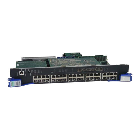
Each of the fixed front panel ports can operate in either half‐duplex or full‐duplex mode of operation. The duplex mode can be determined by either auto‐negotiation or manual configuration. The DFE‐Gold module ports can be configured to control traffic by limiting the rate of traffic accepted into the module and prioritizing traffic to expedite the flow of higher priority traffic through the module. The DFE‐Gold module receives power and backplane connectivity when it is inserted into theMatrix N1, Matrix N3, Matrix N5, Matrix N7, or Matrix E7 chassis. The information concerning the DFE module features and how to configure them to a network are provided in the Enterasys Matrix DFE‐Gold Series Configuration Guide. 4G4202-60 The 4G4202‐60 is an edge‐network switch with 60, 10BASE‐T/100BASE‐TX/1000BASE‐T ports via 60 front‐panel RJ45 connectors. 4G4282-41 The 4G4282‐41 is an edge‐network switch with 40, 10BASE‐T/100BASE‐TX/1000BASE‐T compliant ports via 40 fixed front‐panel RJ45 connectors and a slot for an optional network expansion module (NEM). Optional Network Expansion Module (NEM) The 4G4282‐41 option slot provides access to an installed network expansion module (NEM). Refer to your release notes or the Enterasys Networks web site for the latest available network expansion modules. Specific installation instructions are shipped with each NEM. Enterasys Matrix DFE-Gold Series Modules Hardware Installation Guide... -
Page 24: 4G4202-60 And 4G4282-41 Dfe-Gold Modules
Figure 1-1 ➀ OFFLINE/RESET switch ➁ RJ45 COM (Console Port) ➂ CPU LED ➃ MGMT LED ➄ GROUP SELECT button 4G4202-60 and 4G4282-41 DFE-Gold Modules À Á Â Ã Ä Å Æ È Ç ➅ GROUP selected LEDs ➆ GROUP status LEDs ➇... -
Page 25: Connectivity
• 40, 10BASE‐T/100BASE‐TX/1000BASE‐T switched ports connected through 40, fixed RJ45 front panel connectors, or • 40, 10BASE‐T/100BASE‐TX/1000BASE‐T switched ports and an optional network expansion module. Management Management of the module can be either in‐band or out‐of‐band. In‐band remote management is possible using Telnet, Enterasys Networks’ NetSight application, or WebView™ application. Out‐of‐band management is provided through the RJ45 COM (Communication) port on the front panel using a VT100 terminal or a VT100 terminal emulator. Switch Configuration Using WebView Enterasys Networks’ HTTP‐based Web management application (WebView) is an intuitive web tool for simple management tasks. Switch Configuration Using CLI Commands The CLI commands enable you to perform more complete switch configuration management tasks. For CLI command set information and how to configure the module, refer to the Enterasys Matrix DFE‐Gold Series Configuration Guide. 1‐1) is configured, it can support up to: Enterasys Matrix DFE-Gold Series Modules Hardware Installation Guide ® management ... -
Page 26: Secure Networks Policy Support
Secure Networks Policy Support Policy Enabled Networking manages the allocation of networking infrastructure resources in a secure and effective manner. Using Secure Networks Policy, an IT Administrator can predictably assign appropriate resources to the Users, Applications, and Services that use the network; while blocking or containing access for inappropriate or potentially dangerous network traffic. Using this technology it is possible, for the first time, to align IT services with the needs of specific users and applications, and to leverage the network as a key component of the organization’s security strategy. The Secure Networks Policy Architecture consists of 3 components: Classification Rules, Network Services, and Behavioral Profiles. These are defined as follows: • Classification Rules determine how specific traffic flows (identified by Layer 2, Layer 3, and Layer 4 information in the data packet) are treated by each Switch or Router. In general, Classification Rules are applied to the networking infrastructure at the network edge/ingress point. • Network Services are logical groups of Classification Rules that identify specific networked applications or services. Users may be permitted or denied access to these services based on their role within the organization. Priority and bandwidth rate limiting may also be controlled using Network Services. • Behavioral Profiles (or roles) are used to assign Network Services to groups of users who share common needs–for example Executive Managers, Human Resources Personnel, or Guest Users. Access, resources, and security restrictions are applied as appropriate to each Behavioral Profile. A variety of authentication methods including 802.1X, EAP‐TLS, EAP‐TTLS, and PEAP may be used to classify and authorize each individual user; and the IT Administrator may also define a Behavioral Profile to apply in the absence of an authentication framework. Standards Compatibility The DFE‐Gold modules are fully compliant with the IEEE 802.3‐2002, 802.3ae‐2002, 802.1D‐1998, and 802.1Q‐1998 standards. The DFE‐Gold module provides IEEE 802.1D‐ 1998 Spanning Tree Algorithm (STA) support to enhance the overall reliability of the network and protect against “loop” conditions. LANVIEW Diagnostic LEDs LANVIEW diagnostic LEDs serve as an important troubleshooting aid by providing an ... -
Page 27: Chapter 2: Network Requirements
Failure to do so will produce poor network performance. Note: The Enterasys Matrix DFE-Gold Series Configuration Guide and the Cabling Guide referred to in the following sections can be found on the Enterasys Networks World Wide Web site:... -
Page 28: 10Base-T Network
In normal usage (and typical implementations) there is no need to enable/disable ports for Link Aggregation. The default values will result in the maximum number of aggregations possible. If the switch is placed in a configuration with its peers not running the protocol, no aggregations will be formed and the DFE modules will function normally (that is, Spanning Tree will block redundant paths). For details about the commands involved with configuring the Link Aggregation function, refer to the Enterasys Matrix DFE‐Gold Series Configuration Guide. 10BASE-T Network When connecting a 10BASE‐T segment to any of the fixed front panel ports of the 4G4202‐60 or 4G4282‐41, ensure that the network meets the Ethernet network requirements of the IEEE 802.3‐2002 standard for 10BASE‐T. Refer to the Cabling Guide for details. Note: If a port is to operate at 100 Mbps, Category 5 cabling must be used. Category 3 cabling does not meet 100 Mbps specifications. For 10 Mbps operation only, Category 3 or Category 5 cabling can be used. - Page 29 Read the Release Notes shipped with the DFE-Gold module to check for any exceptions to the supported features and operation documented in this guide. This chapter provides the instructions to install the 4G4202‐60 and 4G4282‐41 DFE‐Gold modules. Follow the order of the sections listed below to correctly install the modules. For information about... Unpacking the DFE‐Gold Module Installing Optional Network Expansion Module (NEM) DFE Module Placement and Installation Rules Installing Module into a Chassis Installing Module into Matrix N3, N1, or N5 Chassis (N3 shown) Connecting to the Network Connecting to COM Port for Local Management Completing the Installation Enterasys Matrix DFE-Gold Series Modules Hardware Installation Guide Important Notice Installation Refer to page... 3-11 3-15...
-
Page 30: Installation Site Requirement
Komponenten sollte durch ein Schloß, einen Schlüssel oder sonstigen Sicherungen geschützt und durch einen Verantwortlichen kontrolliert werden. Unpacking the DFE-Gold Module Unpack the DFE‐Gold module as follows: Open the box and remove the packing material protecting the DFE‐Gold module. Verify the contents of the carton as listed in . Item DFE-Gold module (4G4202-60 Installation Guide Customer Release Notes Remove the tape seal on the non‐conductive bag to remove the DFE‐Gold module. Perform a visual inspection of the DFE‐Gold module for any signs of physical damage. Contact Enterasys Networks if there are any signs of damage. Refer to “Getting Help” on page xviii for details. 4G4282-41) or Quantity Installation... -
Page 31: Installing Optional Network Expansion Module (Nem)
Gold (4xxxxx). No inserte módulos 7xxxxx ni otros módulos legado dentro de un chasis con módulos 4xxxxx. Si lo hace, el chasis no funcionará. on page 3-3 for an explanation of the rules to install E7 (refer to Figure Enterasys Matrix DFE-Gold Series Modules Hardware Installation Guide “DFE Module 3‐2 on page 3‐8) for ... -
Page 32: Examples, Slot Numbers And Module Placement In Matrix E7 Or N7
(Figure Shows one module installed in the chassis. If the chassis is populated with only one 4xxxxx, it must be installed in slot 1. Rule: If only one 4xxxxx is installed in the chassis, it must be in slot 1. Always install a 4xxxxx in slot 1 of the chassis. Example 2 (Figure Shows the chassis fully populated with 4xxxxx modules. All modules may be hot swapped, except the module in slot 1. If the module in slot 2 is designated as a redundant management module, the module in slot 1 may be hot swapped without shutting down the system. The module in slot 2 can be designated using the CLI command set license <license key>. For information on how to use this command, refer to the Enterasys Matrix DFE‐Gold Series Configuration Guide. To access this guide on the web, refer to “Related Documents” on page xvi. Without a designated redundant management module in slot 2, removing the module in slot 1 will shut down the system. Rule: Any module in a 4xxxxx system, including the management module in slot 1, may be hot swapped when there is a 4xxxxx module designated as a redundant management module in slot 2. Examples, Slot Numbers and Module Placement in Matrix E7 or N7 3-1, A) 3-1, B) Installation... -
Page 33: Installing Module Into A Chassis
No corte la bolsa antiestática para sacar el módulo. Tenga en cuenta que si algún objeto cortante entra en contacto con la placa o con los componentes, éstos podrían dañarse. To install a DFE‐Gold module into a Matrix E7 or Matrix N7 chassis, proceed directly to “Preparation” on page 3‐6 to start the installation process. 3-1, C) 3-1, D) Enterasys Matrix DFE-Gold Series Modules Hardware Installation Guide... -
Page 34: Preparation
Remove the module from the plastic bag. (Save the bag in the event the module must be reshipped.) Observe all precautions to prevent damage from Electrostatic Discharge (ESD). Examine the module for damage. If any damage exists, DO NOT install the module. Immediately contact Enterasys Networks. Refer to “Getting Help” on page xviii. Module into Matrix E7 or N7 Chassis Installing To install the module, refer to Figure Caution: To prevent damaging the backplane connectors in the following step, take care that the module slides in straight and properly engages the backplane connectors. - Page 35 Precaución: En el paso 4, tenga cuidado de no llevar las palancas de cierre a un punto en donde estén en contacto con el panel frontal. Si lo hace, podría dañar el módulo y/o el chasis. Refer to the Caution note above, then rotate the two levers into the closed position If the chassis in which the module is installed was powered down for the installation, turn the power supplies on. Check to see that the module CPU LED settles at solid green after a few minutes. If the LED does not turn solid green, refer to Chapter troubleshooting details. Enterasys Matrix DFE-Gold Series Modules Hardware Installation Guide 3‐2. ➅ 4 for ...
-
Page 36: Installing Module Into Matrix E7 Or Matrix N7 Chassis (E7 Shown)
Figure 3-2 Installing Module into Matrix E7 or Matrix N7 Chassis (E7 shown) Ã Â À ➀ Card guides ➁ Slot number 1 ➂ Module card ➃ Metal back panel Á Æ ➄ Upper/lower locking levers (in proper open position) ➅... -
Page 37: Installing Module Into Matrix N3, N1, Or N5 Chassis (N3 Shown)
Precaución: Al mover las palancas a la posición de cerrado, tenga cuidado de no llevarlas a un punto en donde estén en contacto con el panel frontal. Si lo hace, podría dañar el módulo o el chasis. refer to Figure 3‐3 and proceed as described in “Installing Enterasys Matrix DFE-Gold Series Modules Hardware Installation Guide... -
Page 38: Installing Module Into Matrix N3, N1, Or N5 Chassis (Matrix N3 Shown)
Figure 3-3 Æ Ä ➀ Card guides ➁ Slot 1 (Top slot is slot 3.) ➂ Module card ➃ Metal back panel 3-10 Installing Module into Matrix N3, N1, or N5 Chassis (Matrix N3 shown) À ➄ ➅ ➆ Ã Â... -
Page 39: Connecting To The Network
Note: If the DFE-Gold module is being installed in a network using Link Aggregation, there are rules concerning the network cable and port configurations that must be followed for Link Aggregation to operate properly. Before connecting the cables, refer to the Enterasys Matrix DFE-Gold Series Configuration Guide for the configuration information. For details... -
Page 40: Connecting A Twisted Pair Segment To The Dfe-Gold Module
Figure 3-4 ➀ RJ45 connector ➁ RJ45 port connector Verify that a link exists by checking that the port RX (Receive) LED amber, blinking green, or solid green). If the RX LED is OFF and the TX (Transmit) ➃ LED is not blinking amber, perform the following steps until it is on: To view the receive and transmit activity on a group of segments, press the GROUP SELECT button (Groups 1 through 3 on 4G4202‐60 as shown in 4G4202‐60, or Groups 1 through 5 on the 4G4282‐41). Each time the GROUP SELECT button is pressed, the GROUP LED lights up in sequence, indicating which Group is selected. The receive and transmit activity for that group of segments is then indicated by the RX and TX LEDs for each segment. b. Verify that the cabling being used is Category 5 UTP with an impedance between 85 and 111 ohms. If the port is to operate at 100 Mbps, category 5 cabling must be used. Verify that the device at the other end of the twisted pair segment is on and properly connected to the segment. d. Verify that the RJ45 connectors on the twisted pair segment have the proper pinouts and check the cable for continuity. Typically, a crossover cable is used between hub devices. A straight‐through cable is used to connect between switches or hub devices and an end user (computer). Refer to Figure Figure 3‐6 for four‐wire RJ45 connections. Refer to Figure 3‐7 and Figure eight‐wire RJ45 connections. 3-12 Connecting a Twisted Pair Segment to the DFE-Gold Module À... -
Page 41: Four-Wire Crossover Cable Rj45 Pinouts, Connections Between Hub Devices
Between Switches and End User Devices À à ➀ RJ45 device port ➁ Other device port Enterasys Matrix DFE-Gold Series Modules Hardware Installation Guide  ➂ RJ45-to-RJ45 crossover cable ➃ RX+/RX- and TX+/TX- connections. These connections must share a common color pair. -
Page 42: Eight-Wire Crossover Cable Rj45 Pinouts, Connections Between Hub Devices
Figure 3-7 Devices ➀ RJ45 device port ➁ Other device port Figure 3-8 Between Switches and End User Devices ➀ RJ45 device port ➁ Other device port 3-14 Eight-Wire Crossover Cable RJ45 Pinouts, Connections Between Hub À Eight-Wire Straight-Through Cable RJ45 Pinouts, Connections À... -
Page 43: Connecting To Com Port For Local Management
Connecting to COM Port for Local Management This section describes how to install a UTP straight‐through cable with RJ45 connectors and optional adapters to connect a PC, a VT series terminal, or a modem to a Enterasys Networks DFE‐Gold module. Note: You can connect to any DFE‐Gold module in the chassis to access local management for the DFE‐Gold system. This section also provides the pinout assignments of the adapters. What Is Needed The following is a list of the user‐supplied parts that may be needed depending on the connection: • RJ45‐to‐DB9 female adapter • UTP straight‐through cable with RJ45 connectors • RJ45‐to‐DB25 female adapter • RJ45‐to‐DB25 male adapter With a UTP straight‐through cable with RJ45 connectors and RJ45‐to‐DB9 adapter, you can connect products equipped with an RJ45 COM port to an IBM or compatible PC running a VT series emulation software package. With a UTP straight‐through cable and RJ45‐to‐DB25 female adapter, you can connect products equipped with an RJ45 COM port to a VT series terminal or VT type terminals running emulation programs for the VT series. With a UTP straight‐through cable and an RJ45‐to‐DB25 male adapter, you can connect products equipped with an RJ45 COM port to a Hayes compatible modem that supports 9600 baud. Enterasys Matrix DFE-Gold Series Modules Hardware Installation Guide 3-15... -
Page 44: Connecting To An Ibm Pc Or Compatible Device
Connecting to an IBM PC or Compatible Device To connect an IBM PC or compatible device, running the VT terminal emulation, to an Enterasys Networks module COM port (Figure Connect the RJ45 connector at one end of a UTP straight‐through cable communications COM port also known as a Console port.) Plug the RJ45 connector at the other end of the UTP straight‐through cable RJ45‐to‐DB9 adapter Connect the RJ45‐to‐DB9 adapter Turn on the PC and configure your VT emulation package with the following parameters: Parameter Mode Transmit Bits Parity Stop Bit When these parameters are set, the Local Management password screen will display. Refer to the appropriate Enterasys Matrix DFE‐Gold Series Configuration Guide for further information. 3-16 3‐9), proceed as follows: ➁ on the Enterasys Networks module. (The COM port is ➂ ➂ to the communications port on the IBM PC Setting 7 Bit Control Transmit=9600... -
Page 45: Connecting To A Vt Series Terminal
(Figure 3‐10), use a UTP straight‐through cable with RJ45 connectors and an RJ45‐to‐DB25 female adapter, and proceed as follows: Connect the RJ45 connector at one end of the UTP straight‐through cable ➁ COM port on the Enterasys Networks module. Plug the RJ45 connector at the other end of the UTP straight‐through cable RJ45‐to‐DB25 female adapter Connect the RJ45‐to‐DB25 adapter  À ➂ ➂ to the port labeled COM on the VT terminal Enterasys Matrix DFE-Gold Series Modules Hardware Installation Guide Á ➂ RJ45-to-DB9 PC adapter ➃ IBM PC or compatible device ➀ to the ➀ into the ➃ 3-17... -
Page 46: Connecting A Vt Series Terminal
Turn on the terminal and access the Setup Directory. Set the following parameters on your terminal: Parameter Mode Transmit Bits Parity Stop Bit When these parameters are set, the Local Management password screen will display. Refer to the Enterasys Matrix DFE‐Gold Series Configuration Guide for further information. Figure 3-10 ➀ UTP straight-through cable with RJ45 connectors ➁ RJ45 COM port 3-18 Connecting a VT Series Terminal ➃ ➂ Setting 7 Bit Control Transmit=9600 8 Bits, No Parity... -
Page 47: Connecting To A Modem
Transmit Bits Parity Stop Bit When these parameters are set, the Local Management password screen will display. Refer to the Enterasys Matrix DFE‐Gold Series Configuration Guide for further information. ➂ ➂ to the communications port on the modem ➃ ➄ , you can configure the switch remotely. Setting 7 Bit Control Transmit=9600 8 Bits, No Parity 1 Stop Bit Enterasys Matrix DFE-Gold Series Modules Hardware Installation Guide ➀ to the ➀ into the ➃ 3-19... -
Page 48: Connecting To A Modem
Figure 3-11 ➀ UTP straight-through cable with RJ45 connectors ➁ RJ45 COM port ➂ RJ45-to-DB25 modem adapter 3-20 Connecting to a Modem Ä Ã Â À ➃ Local modem ➄ Remote modem Á Installation... -
Page 49: Adapter Wiring And Signal Assignments
Blue Green Orange Yellow DB25 Conductor Blue Yellow Green Orange Enterasys Matrix DFE-Gold Series Modules Hardware Installation Guide Signal Receive (RX) Transmit (TX) Ground (GRD) Request to Send (RTS) Clear to Send (CTS) Signal Transmit (TX) Receive (RX) Clear to Send (CTS) -
Page 50: Completing The Installation
Completing the Installation Completing the DFE module installation depends on if the module is being installed in • A new DFE module system (refer to “Completing the Installation” on page 3‐22), or • An established, operating DFE module system (refer to “Completing the Installation of a DFE‐Gold Module in an Existing System” on page 3‐24). Completing the Installation of a New System In a new system of DFE modules, one of the installed DFE modules will become the management module on chassis power up, and all DFE modules will automatically be set to the factory default values. A complete list of the factory default values are provided in Chapter 3 of the Enterasys Matrix DFE‐Gold Series Configuration Guide. After installing all DFE‐Gold modules into the host chassis and making the connections to the network, proceed to the following First‐Time Log‐In Using a Console Port Connection procedure to access the module management startup screen from your PC, terminal, or modem connection. 3-22 Modem Port Adapter Wiring and Signal Diagram DB25 Conductor Blue Orange Green... - Page 51 Read-Only access; rw for Read-Write access; and admin for super-user access to all modifiable parameters. The default password is set to blank (carriage return). For information on changing these default passwords, refer to Chapter 3 in the Enterasys Matrix DFE-Gold Series Configuration Guide Start the Command Line Interface (CLI) from the module’s local console port as follows:...
-
Page 52: Completing The Installation Of A Dfe-Gold Module In An Existing System
Andover, MA 01810-1008 U.S.A. Phone: +1 978 684 1000 E-mail: support@enterasys.com WWW: http://www.enterasys.com (c) Copyright Enterasys Networks, Inc. 2003 Chassis Serial Number: Chassis Firmware Revision: xx.xx.xx Matrix N7(su)-> Completing the Installation of a DFE-Gold Module in an Existing System In an established DFE module system, •... - Page 53 For information on the set password and set system login commands, refer to Chapter 3 in the Enterasys Matrix DFE-Gold Series Configuration Guide The DFE‐Gold module is now ready to be configured. For information about setting the IP ...
- Page 54 3-26 Installation...
-
Page 55: Chapter 4: Troubleshooting
This chapter provides information concerning the following: • “Using LANVIEW” (page 4‐1) • “Troubleshooting Checklist” (page 4‐5) • “Overview of DFE‐Gold Module Shutdown Procedure” (page 4‐7) • “Recommended Shutdown Procedure Using OFFLINE/RESET Switch” (page 4‐8) • “Last Resort Shutdown Procedure Using OFFLINE/RESET Switch” (page 4‐8) Unless otherwise noted, the following information applies to all DFE modules. Using LANVIEW The modules use a built‐in visual diagnostic and status monitoring system called LANVIEW. The LANVIEW LEDs (Figure status to aid in diagnosing network problems. About the Management (MGMT) LED The MGMT LED (shown in Figure Management Module to control the management functions for all DFE modules in the chassis. The Management Module handles all IP requests to the chassis IP address, such as PING, Telnet, SNMP, HTTP, etc. The Management Module also handles the CLI configuration sessions via the console port. So, when you plug into a DFE module COM port to configure a DFE module in the chassis, it is handled by the Management Module regardless of the DFE module COM port that you use. Troubleshooting 4‐1) allow quick observation of the network 4‐1) indicates when the module is serving as the Matrix DFE-Gold Series Modules Hardware Installation Guide... -
Page 56: Viewing The Receive And Transmit Activity
Viewing the Receive and Transmit Activity On the 4G4202‐60 and 4G4282‐41, you can view the receive and transmit activity on the RX and TX LEDs. However, only one group of 20 ports may be viewed at a time. To view the receive and transmit activity on a group of attached segments, press the GROUP SELECT button (see Figure 4‐1) to step to the group of interest (Groups 1 ‐ 3 for the 4G4202‐60, and Groups 1 ‐ 5 for the 4G4282‐41). Each time the GROUP SELECT button is pressed, the GROUP LED lights up in sequence, indicating which group is selected. The receive and transmit activity for that group of segments is then indicated by the RX and TX LEDs for each port. Figure 4-1 LANVIEW LEDs À Á À Á ➀ MGMT LED ➁ Group 1, Port 1 LEDs Troubleshooting... -
Page 57: Lanview Leds
Recommended Action None. None. None. Ensure chassis has adequate power. None. If the LED remains amber for several minutes, contact Enterasys-Networks for technical support. None. None. None. None. This state is activated when the OFFLINE/RESET switch is pressed for less than 1 second to start the process of an orderly shutdown. - Page 58 While in this state, you have 60 seconds to safely remove the DFE-Gold module from the chassis. None. None. None. Contact Enterasys-Networks for technical support. If it is known that the port should be active and is not, contact Enterasys-Networks for technical support.
-
Page 59: Troubleshooting Checklist
Verify that all network connections between the network management station and the module are valid and operating. If the problem continues, contact Enterasys-Networks for technical support. Matrix DFE-Gold Series Modules Hardware Installation Guide 4‐2 for a checklist of problems, 3, and that the host chassis is providing Appendix A for proper COM port pinouts. - Page 60 STA. Review the network design and delete unnecessary loops. If the problem continues, contact Enterasys-Networks for technical support. Position of Mode switch Reenter the lost parameters as necessary. Refer (7), Persistent Data to the Matrix DFE-Gold Series Configuration Reset, was changed Guide for the instructions to configure the device.
-
Page 61: Overview Of Dfe-Gold Module Shutdown Procedure
The DFE‐Gold modules installed in a Matrix E7, Matrix N1, Matrix N3, Matrix N5, or Matrix N7 chassis are interdependent and operate under a single IP address as a single, distributed switch system (hardware, databases, and persistent storage). In this operating environment, the DFE‐Gold module must shut down in an orderly fashion to ensure that the other modules in the system and other devices on the network are notified of the impending change. The device(s) can then make intelligent decisions and stabilize the network before the change is made; thereby increasing network availability. You can shut down a DFE‐Gold module in an operating system using the OFFLINE/ RESET switch shown in Figure module. • Recommended shutdown procedure (page 4‐8) • Last resort shutdown procedure (not recommended) (page 4‐8) Figure 4-13 ➀ OFFLINE/RESET switch (in similar location on 4G4282-41) 4‐13. There are two procedures to shut down a DFE‐Gold OFFLINE/RESET Switch Matrix DFE-Gold Series Modules Hardware Installation Guide À... -
Page 62: Recommended Shutdown Procedure Using Offline/Reset Switch
Note: The only safe time to pull a DFE-Gold module out of the chassis is when the CPU LED is alternately flashing amber/off. Otherwise, system operation will be interrupted. Last Resort Shutdown Procedure Using OFFLINE/RESET Switch Caution: This method of shutting down a DFE module is not recommended except as a last resort, because all processes currently running on the module will be interrupted resulting in loss of frames. -
Page 63: Appendix A: Specifications
This appendix provides information about the following: • “DFE‐Gold Module Specifications” (page A‐1) • “COM Port Pinout Assignments” (page A‐3) • “Regulatory Compliance” (page A‐3) Enterasys Networks reserves the right to change the specifications at any time without notice. DFE-Gold Module Specifications Table A‐1 provides the I/O ports, processors and memory, physical, and environmental module specifications for DFE‐Gold modules, 4G4202‐60 and 4G4282‐41. Unless noted differently, the specifications apply to all five DFE modules. Table A-1 Specifications Item 4G4202-60 Ports Ports 1 through 60 4G4282-41 Ports Ports 1 through 40 Option Slot Specifications Specification Sixty 10BASE-T/100BASE-TX/1000BASE-T compliant ports, via sixty RJ45 connectors. - Page 64 4.10 kg (9.0 lb) (one module without packaging) For the MTBF hours for these products, refer to the MTBF web site at URL http://www.enterasys.com/support/mtbf/ 5°C to 40°C (41°F to 104°F) -30°C to 73°C (-22°F to 164°F) 5% to 90% (non-condensing)
-
Page 65: Com Port Pinout Assignments
COM Port Pinout Assignments The COM port is a serial communications port for local access to Local Management. Refer to Table Table A-2 COM Port Pin Assignments Signal Name Transmit Data (XMT) Clear to Send (CTS) Data Set Ready (DSR) Receive Data (RCV) Signal Ground (GND) Request to Send (RTS) Data Terminal Ready (DTR) Data Carrier Detect (DCD) Regulatory Compliance The 4G4202‐60 and 4G4282‐41 meet the safety and electromagnetic compatibility (EMC) ... - Page 66 Regulatory Compliance A-4 Specifications...
-
Page 67: Chapter B: Mode Switch Bank Settings And Optional Installations
Para realizar cualquiera de los procedimientos especificados en el apéndice, no olvide utilizar la pulsera electrostática que acompaña el chasis para minimizar los efectos de las descargas de electricidad estática. Mode Switch Bank Settings and Optional Installations Matrix DFE-Gold Series Modules Hardware Installation Guide B-1... -
Page 68: Setting The Mode Switches
Data on the next power‐up of the module. All user‐entered parameters, such as the IP address, module names, etc., are reset to the factory default settings. Once the module resets, you can either use the factory default settings or reenter your own parameters. • Switch 8 – Clear Admin Password. Changing the position of this switch clears the admin password, and restores the factory default password on the next power‐up of the module. Once the module resets, you can either use the factory default settings or reenter your own password. Note: Do not change the position of Switch 8 unless it is necessary to reset the admin password to its factory default setting. B-2 Mode Switch Bank Settings and Optional Installations B‐3 show the location of the mode switches and the switch ... -
Page 69: Memory Locations And Replacement Procedures
Mode Switch Location on 4G4202-60 and 4G4282-41 ➀ ➀ Mode switch pack Memory Locations and Replacement Procedures In the event that the Dual In‐line Memory Module (DIMM) or DRAM Single In‐line Memory Module (SIMM) (FLASH memory) needs to be replaced, the following sections describe how to access, locate and replace these memory modules. If you have questions concerning the replacement of either memory module, refer to “Getting Help” on page xviii for details on how to contact Enterasys Networks. Location of DRAM SIMM and DIMM Memory Modules Figure B‐2 and Figure B‐3 show the locations of the DRAM SIMM and DIMM on the each main board of the 4G4202‐60 and the 4G4282‐41, respectively. Matrix DFE-Gold Series Modules Hardware Installation Guide B-3... -
Page 70: Memory Module Locations On The 4G4202-60
1. The DIMM on the 4G4202-60 is not considered to be a field replaceable unit. Figure B-3 ➀ DIMM B-4 Mode Switch Bank Settings and Optional Installations Memory Module Locations on the 4G4202-60 ➁ DRAM SIMM Memory Module Locations on the 4G4282-41 ➁... -
Page 71: Dimm Replacement Procedure (4G4282-41
DIMM Replacement Procedure (4G4282-41) Note: The following DIMM replacement instructions apply to the 4G4282-41 only. The DIMM is not considered a field replaceable part on the 4G4202-60. Contact Enterasys support if this part fails and needs a replacement. Removing the DIMM Caution: Observe all Electrostatic Discharge (ESD) precautions when handling sensitive electronic equipment. -
Page 72: Removing Nem And Dimm Connector Location On 4G4282-41
Main PC board ➂ Screws (3) Refer to Figure simultaneously lift the DIMM enough to release it from the connector fingers. Figure B-2 ➀ Connector arms Rotate the DIMM upwards, then remove it from the connector fingers. B-6 Mode Switch Bank Settings and Optional Installations Removing NEM and DIMM Connector Location on 4G4282-41 Â Ã B‐2. Push the connector arms away from the DIMM and Removing the Existing DIMM from 4G4282-41 À Â ➁... -
Page 73: Installing The Dimm On 4G4282-41
Installing the DIMM Caution: Observe all Electrostatic Discharge (ESD) precautions when handling sensitive electronic equipment. Precaución: Al trabajar con equipos electrónicos sensibles, tome todas las precauciones de seguridad para evitar descargas de electricidad estática. To install a DIMM, refer to Figure Insert the DIMM down between the connector fingers. Pivot the DIMM downward so the tabs on the connector arms align with the two DIMM alignment notches. With the two connector arms spread outward, push the DIMM down between the connector arms. Then release the two connector arms to lock the DIMM into place. Figure B-3 Installing the DIMM on 4G4282-41 Â... -
Page 74: Dram Simm Replacement Procedure For 4G4202-60 Or 4G4282-41
To remove the existing DRAM SIMM, proceed as follows: Locate the DRAM SIMM connector on the main PC board. Refer back to Figure Push the connector arms away from the DRAM SIMM, as shown in Figure enough to release the DRAM SIMM from the connector contacts. Figure B-4 ➀ Connector arms Pull the DRAM SIMM straight up and remove it from the connector contacts. B-8 Mode Switch Bank Settings and Optional Installations Removing Existing DRAM SIMM from 4G4202-60 or 4G4282-41 À Â ➁ DRAM SIMM Á À ➂... -
Page 75: Installing The Dram Simm
Installing the DRAM SIMM on 4G4202-60 or 4G4282-41 Caution: Observe all Electrostatic Discharge (ESD) precautions when handling sensitive electronic equipment. Precaución: Al trabajar con equipos electrónicos sensibles, tome todas las precauciones de seguridad para evitar descargas de electricidad estática. To install a DRAM SIMM, refer to Figure Push the connector arms away from the DRAM SIMM enough to insert the DRAM ... - Page 76 Memory Locations and Replacement Procedures B-10 Mode Switch Bank Settings and Optional Installations...
- Page 77 Matrix N1 chassis module installation into Matrix N3 chassis module installation into 3-6, Matrix N5 chassis module installation into Matrix N7 chassis module installation into Memory locations DIMM and SIMM Mode Switch setting of Module features Index 3-11 3-15 3-25 Index-1...
- Page 78 Network connecting to 3-11 Network expansion module introduction to Network Requirements list of Optional network expansion module installation of introduction to Pinout assignments console port Pinouts crossover 3-13, 3-14 straight-through 3-13, 3-14 Ports 1-Gigabit Ethernet Receive LEDs viewing of Regulatory Compliance Related manuals obtaining Required Tools...