Table of Contents
Advertisement
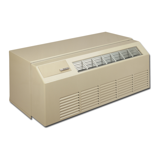
Dynaline
A Combination Gas Heating/Electric Cooling System
Designed to Serve an Individual Room or Zone
ARCHITECT'S AND ENGINEER'S MANUAL
3
™
Apartments and Senior Housing
1
•
Four BTU/h Capacities
•
12 - 20 MBTU Gas Heat
•
Low Heating Amp Draw
•
R-410A Refrigerant
Ideal for Hotels/Motels,
Suburban Dynaline 3 A&E Manual 12/2016 Rev.1
Advertisement
Table of Contents

Related Manuals for Suburban Dynaline 3

Summary of Contents for Suburban Dynaline 3
- Page 1 Designed to Serve an Individual Room or Zone ARCHITECT’S AND ENGINEER’S MANUAL • Four BTU/h Capacities • 12 - 20 MBTU Gas Heat • Low Heating Amp Draw • R-410A Refrigerant Ideal for Hotels/Motels, Apartments and Senior Housing Suburban Dynaline 3 A&E Manual 12/2016 Rev.1...
- Page 2 INTRODUCTION The Surburban Difference Suburban developed the first gas-fired package terminal air conditioner (PTAC) in 1985. Now in its third generation design, Suburban is a leading supplier to the senior housing industry as well as other small commercial markets. Dynaline...
-
Page 3: Table Of Contents
Suburban Limited Warranty ........36-37... -
Page 4: Operating Cost Analysis
*BIN Hours are the number of hours of operation per year at the mid-point temperature Suburban will gladly prepare a BIN Hour Cost Analysis for your location. For specific to a geographical more information, please contact the Suburban Sales/Marketing Department location. - Page 5 2013 such as Syracuse, NY, with a 2º design temperature, the cost to TYPE COST heat with Dynaline 3 can save 80% in utility costs compared to electric resistance. When compared to heat pumps, Dynaline 3 Electricity 12.1¢ / kwh can save 66%.
-
Page 6: Features
(supplied), or field direct and contaminants into on the evaporator coil. wire, to suit design or code requirements. the conditioned area. Suburban Dynaline 3 A&E Manual 12/2016 Rev.1... - Page 7 Figure 3 washable media. generator is operating. Electronic control board has 24V input terminals to receive lock-out signal. UNIT WALL SLEEVE DIMENSIONS Figure 4 Specifications subject to change without notice. Suburban Dynaline 3 A&E Manual 12/2016 Rev.1...
-
Page 8: Dynaline 3 Specifications
26 oz. 28 oz. Rated Load amps Locked rotor Amps Rated capacity (BTU/h) 14,100 10,300 8,050 6,600 (Normally closed 24V) Compressor lock-out relay 5VA enrush - 4V constant Specifications subject to change without notice. Suburban Dynaline 3 A&E Manual 12/2016 Rev.1... -
Page 9: Suggested Bid Specifications
Each unit shall consist of a chassis, wall case/sleeve, outside grille and room cabinet. Units shall be UL listed and/or ETL design certified and shall be Suburban Manufacturing Company DYNALINE 3 models, or equivalents. The units shall be located as shown on ™... - Page 10 WARRANTY: There shall be a one-year limited warranty on parts and labor and a five-year limited warranty on the compressor and heat exchanger. Suburban Dynaline 3 A&E Manual 12/2016 Rev.1...
-
Page 11: Installing Dynaline 3
American National Standard Z21.86/ETL 2.32 and UL 484. Dynaline 3 is designed for use with Natural gas or Propane gas only. Each Dynaline 3 unit is carefully packed in a container to withstand the load conditions encountered in normal transit and handling. If inspection reveals any damages, do not install the unit. -
Page 12: Framing
NOTE: UNITS APPROVED FOR 0" CLEARANCE TO COMBUSTIBLE CONSTUCTIONS TOP, SIDES, AND BOTTOM. FRONT AND REAR CLEARANCE NOT APPLICABLE AS THERE CAN BE NO CONSTRUCTION COMBUSTIBLE OR NON-COMBUSTIBLE TO THE FRONT OR REAR OF THE OPENING. Figure 7 Suburban Dynaline 3 A&E Manual 12/2016 Rev.1... -
Page 13: Knockdown Wall Sleeve
NOTE: Do not discard packing inside carton. It may be used as a temporary cover for weather and construction protection. To cover the wall sleeve opening, cut cardboard insert along the perforated line, fold and place in rear of sleeve. Figure 8 Suburban Dynaline 3 A&E Manual 12/2016 Rev.1... -
Page 14: Installing The Chassis
NOTE: X" CAN BE 0" IF SLEEVE IS FLUSH WITH FINISHED INTERIOR WALL. SLOPE DOWN TO THE OUTSIDE SURFACE OF FINISHED MIN. (PROJECTION BEYOND EXTERIOR WALL) FLOOR OR TOP OF CARPET Figure 9 Suburban Dynaline 3 A&E Manual 12/2016 Rev.1... - Page 15 DO NOT PUT HOLES THROUGH OR DRIVE SCREWS INTO WALL SLEEVE BOTTOM! 1" (MIN.) 1" SLOPE DOWN TO THE OUTSIDE 1" MIN. (PROJECTION BEYOND WALL) SURFACE OF FINISHED FLOOR OR TOP OF CARPET Figure 11 Suburban Dynaline 3 A&E Manual 12/2016 Rev.1...
- Page 16 Figure 12 Suburban Dynaline 3 A&E Manual 12/2016 Rev.1...
-
Page 17: Installation Data
The unit must be disconnected from the gas supply piping system during any pressure testing of the gas supply system at test pressures equal to or greater than 1/2 PSIG. Figure 13 Suburban Dynaline 3 A&E Manual 12/2016 Rev.1... -
Page 18: Installing Rear Gas Connection
10. Chassis installation into wall case can now be completed by installing nipple, union and shutoff valve (field supplied) in accordance with local code. 11. Check all joints for gas leaks. NOTE: Wall sleeve must extend beyond the finished exterior wall surface 1-5/8" minimum. Suburban Dynaline 3 A&E Manual 12/2016 Rev.1... -
Page 19: Air Discharge Package
• Air Discharge Package (See Table 6.) Discharge air is dependent on Dynaline 3 model selected, mode of operation (heat or cool), and length of total air discharge application. When additional length is required, a connector is used in conjunction with the air discharge package. - Page 20 Removing the baffle results in a 70/30 Figure 16 split. (On model DL3-1622 you must remove the baffle). For best results unit should be run on Hi only when using discharge package. Suburban Dynaline 3 A&E Manual 12/2016 Rev.1...
-
Page 21: Air Discharge Connector
(On model DL3-1622 you must remove the baffle.) AIR DISCHARGE The 43" insulated connector plenum CONNECTOR attaches to either side of the air discharge adaptor. It can be cut to the desired length. Ends have male/female collars. Figure 19 Suburban Dynaline 3 A&E Manual 12/2016 Rev.1... -
Page 22: Leveling Legs
TINNERMAN CABINET FRONT Figure 21 Dynaline 3 chassis may be wired to a central location, usually the front desk, ENERGY where they may be controlled by a toggle switch or other means MANAGEMENT in a control panel (field supplied). The units remain de-energized until... -
Page 23: Optional Drain Kit
Standard NOTE: Consult with factory engineers before using any other outdoor grilles grille or special exterior treatment. Application of non-Suburban products could severely affect the overall operating characteristics of the flue unit, causing hazardous or unsatisfactory performance. Suburban Dynaline 3 A&E Manual 12/2016 Rev.1... -
Page 24: Optional 2-Psig Regulator
MAY OR MAY NOT BE REQUIRED. CHECK LOCAL CODES. UNION LOW PRESSURE UNION SHUTOFF VALVE LOW PRESSURE REGULATOR SHUTOFF VALVE (PART NO. 160899) REGULATOR GAS INLET (PART NO. 160899) GAS INLET Figure 24 Suburban Dynaline 3 A&E Manual 12/2016 Rev.1... -
Page 25: Electrical Connections And Wiring
Unit is capable of operating set-back (5-wire) thermostat. NOTE: Connecting remote thermostat overrides the built-in thermostat and no digital read out will be displayed on the control panel. There is no need to disconnect the chassis’ built-in thermostat. Suburban Dynaline 3 A&E Manual 12/2016 Rev.1... - Page 26 Ladder Diagram: 208/230 V.A.C. Figure 26 Suburban Dynaline 3 A&E Manual 12/2016 Rev.1...
- Page 27 Schematic: 277 V.A.C. Figure 27 Suburban Dynaline 3 A&E Manual 12/2016 Rev.1...
- Page 28 Ladder Diagram: 277 V.A.C. Figure 28 Suburban Dynaline 3 A&E Manual 12/2016 Rev.1...
- Page 29 Dynaline 3 incorporates an A/C compressor lock-out capability. This feature allows the compressor circuit to be locked out when facility power is supplied by a standby emergency power generator. This is done by routing 24-volt lead wires from a 208/230/24 V.A.C.
-
Page 30: Unit Controls And Functions
To gain access to the control rod, the cabinet front must be removed. (See Figure 30.) NOTE: Operating the unit with the vent open could reduce efficiency of the unit in both heating and cooling modes. Figure 30 Suburban Dynaline 3 A&E Manual 12/2016 Rev.1... -
Page 31: Operating Instructions - Built-In Thermostat
30-second purge cycle, then goes off. The room air blower will continue to operate for approximately 90 seconds at which time the circuit is opened and the room air blower goes off. Suburban Dynaline 3 A&E Manual 12/2016 Rev.1... -
Page 32: Operating Instructions - Remote Thermostat
5. Using the “System” key pad, depress “Fan” key until desired speed lamp is illuminated. NOTE: When Dynaline 3 is controlled by a wall thermostat, the sequence of operation is the same as with built-in thermostat control; however, the temperature setting and system functions are selected at the wall thermostat. -
Page 33: Operating Tips
Upon temperature rise, the switch will close and the compressor will again come on provided that the thermostat is still calling for cooling. NOTE: Dynaline 3 has a built-in 5-minute delay between compressor cycles. Anytime the compressor cycle is interrupted either manually, through the thermostat, a power interruption, etc., the compressor will not restart for 5... -
Page 34: Accessory Description Review
Decor Base Panel (conceals gas/electric connections) Condensate Drain Kit Wall Thermostat 24 VAC heat/cool 88" Line Cord Accessory (Use with Dynaline 3 chassis when replacing DL/DLII units in retrofit applications where the electrical receptacle is more than 20" right of wall opening.) -
Page 35: Dynaline 3 Airflow
The grille is installed from the factory to deliver horizontal air flow. To change the airflow to vertical, simply remove the grille and reinstall in the opposite position. Suburban Dynaline 3 A&E Manual 12/2016 Rev.1... -
Page 36: Suburban Limited Warranty
A new or remanufactured part to replace any defective part will be provided to your dealer, service agency or local gas company, at Suburban’s sole option, without charge for the part itself, FOB the shipping point. THE EXCHANGED PART WILL BE WARRANTED FOR ONLY THE UNEXPIRED PORTION OF THE ORIGINAL WARRANTY. - Page 37 9. Fuel or electricity costs or increases in such costs from any reason whatsoever. 10. Suburban products whose serial number has been altered, defaced or removed. 11. Suburban products installed or warranty claims originating outside the Continental U.S.A., Alaska, Hawaii and Canada.
-
Page 38: Dynaline 3 Ptac Features And Benefits
Condenser fan draws Room ambient and set point condensate from bottom. Warm temperatures are easy to read. condenser air, combined with coil temperature, accelerates the evaporation process. Positive drain kits are also available. Suburban Dynaline 3 A&E Manual 12/2016 Rev.1... - Page 39 Electrical Components: hot surface ignites the burner without standing pilot lights. Located on the indoor side Gas is conserved and of the wall, they’re protected safety is ensured. from the weather. Suburban Dynaline 3 A&E Manual 12/2016 Rev.1...
- Page 40 Please consult the Suburban Manufacturing website at www.SuburbanManufacturing.com for the latest product literature. Detailed dimensional data is available upon request. A complete warranty statement can be found in each product’s Installation/Operation Manual, on our website. As part of the Suburban continuous improvement program, specifications are subject to change without notice.