Table of Contents
Advertisement
Quick Links
AM/FM RADIO KIT
MODEL AM/FM-108K
INTEGRAL CIRCUIT, 9 TRANSISTORS, 4 DIODES
Assembly and Instruction Manual
Elenco
®
Electronics, Inc.
Copyright © 2003, 1989 by Elenco
®
Electronics, Inc. All rights reserved.
Revised 2003
REV-X
753508
No part of this book shall be reproduced by any means; electronic, photocopying, or otherwise without written permission from the publisher.
Advertisement
Table of Contents

Related Manuals for Elenco Electronics AM/FM-108K


Summary of Contents for Elenco Electronics AM/FM-108K
- Page 1 AM/FM RADIO KIT MODEL AM/FM-108K INTEGRAL CIRCUIT, 9 TRANSISTORS, 4 DIODES Assembly and Instruction Manual Elenco ® Electronics, Inc. Copyright © 2003, 1989 by Elenco ® Electronics, Inc. All rights reserved. Revised 2003 REV-X 753508 No part of this book shall be reproduced by any means; electronic, photocopying, or otherwise without written permission from the publisher.
- Page 2 identify the parts that you will need for the AM radio as listed below. DO NOT OPEN the bags listed for the FM radio. A separate parts list will be shown for the FM radio after you have completed the AM radio. PARTS LIST FOR THE AM RADIO SECTION If you are a student, and any parts are missing or damaged, please see instructor or bookstore.
- Page 3 IDENTIFYING RESISTOR VALUES Use the following information as a guide in properly identifying the value of resistors. BAND 1 1st Digit Color Digit Black Brown Orange Yellow Green Blue Violet Gray White IDENTIFYING CAPACITOR VALUES Capacitors will be identified by their capacitance value in pF (picofarads), nF (nanofarads), or µF (microfarads). Most capacitors will have their actual value printed on them.
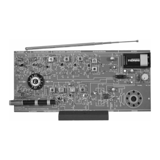
- Page 4 INTRODUCTION The Elenco ® Superhet 108 AM/FM Radio Kit is a “superheterodyne” receiver of the standard AM (amplitude modulation) and FM (frequency modulation) broadcast frequencies. The unique design of the Superhet 108 allows you to place the parts over their corresponding symbol in the schematic drawing on the surface of the printed circuit board during assembly.
- Page 5 CONSTRUCTION Introduction The most important factor in assembling your Superhet 108 AM/FM Radio Kit is good soldering techniques. Using the proper soldering iron is of prime importance. A small pencil type soldering iron of 25 - 40 watts is recommended. The tip of the iron must be kept clean at all times and well tinned.
- Page 6 SEMICONDUCTOR PARTS FAMILIARIZATION This section will familiarize you with the proper method used to test the transistors and the diode. TRANSISTOR TEST Refer to the parts list and find transistors. These are NPN transistors. Refer to Test A for locating the Emitter, Base and Collector.
- Page 7 AUDIO AMPLIFIER The purpose of the Audio Amplifier is to increase the audio power to a level sufficient to drive an 8 ohm speaker. To do this, DC (direct current) from the battery is converted by the amplifier to an AC (alternating current) in the speaker.
-
Page 8: Assembly Instructions
ASSEMBLY INSTRUCTIONS We will begin by installing resistor R43. Identify the resistor by its color and install as shown on page 4. Be careful to properly mount and solder all components. Diodes, transistors and electrolytic capacitors are polarized, be sure to follow the instructions carefully so that they are not mounted backwards. Check the box when you have completed each installation. - Page 9 ASSEMBLY INSTRUCTIONS Note: Mount the Pot/SW, earphone jack, and speaker to the foil side of the PC board. Knob Washer Cut off locating pin Plastic Washer Solder all 5 tabs to PC board Figure F Figure G If the speaker pad has center and outside pieces, then remove them.
- Page 10 STATIC MEASUREMENTS POWER TEST For all measurements, connect your equipment GND to circuit GND TP15. Set your VOM (Volt-Ohm- Millimeter) to read 2 amps DC. Connect the meter to the circuit as shown in Figure 6. Make sure that the volume control is in the OFF position (turned fully counter-clockwise).
- Page 11 If you do not have an audio generator, skip the following test and go directly to Section 2. DYNAMIC MEASUREMENTS GAIN Connect the VOM and audio generator to the circuit as shown in Figure 8. Normally the AC gain is measured at a frequency of 1kHz.
- Page 12 If an oscilloscope is not available, skip the following test and go directly to Section 2. AC BANDWIDTH Connect the oscilloscope and audio generator to your circuit as shown in Figure 9. Set the audio generator for a frequency of 1kHz and minimum voltage output.
- Page 13 MAXIMUM POWER OUTPUT The maximum power output before distortion due to “clipping” can be calculated using the voltage Vclp obtained in the Distortion Step as follows: Vpeak (Vp) = Vclp/2 Vroot mean squared (Vrms) = Vp x .7 Max power out = (Vrms) /8 ohms = (Vclp x .35) Maximum power output should be greater than 200 milliwatts.
- Page 14 Generator TP15 Vp = Vclp/2 Vrms = Vp x .7 Max power out = (Vrms) Since the battery power equals the battery voltage times the current taken from the battery; calculate the battery power: Battery power = Imax x V supply Since the efficiency (N) is equal to the Max power out divided by the Battery power, we can now calculate the efficiency of the audio amplifier.
- Page 15 AM DETECTOR AND AGC STAGE The purpose of the detector is to change the amplitude modulated IF signal back to an audio signal. This is accomplished by a process called detection or demodulation. modulated IF signal is applied to a diode in such a way as to leave only the negative portion of that signal (see Figure 12).
- Page 16 ASSEMBLY INSTRUCTIONS C34 - 100µF Lytic (see Figure B) T6 - AM IF Coil (Yellow Dot) R35 - 27kΩ Resistor (red-violet-orange-gold) TP5 - Test Point Pin (see Figure A) C32 - 10µF Lytic (see Figure B) R36 - 3.3kΩ Resistor (orange-orange-red-gold) C33 - .02µF Discap (203) or .022µF Discap (223)
- Page 17 DYNAMIC MEASUREMENTS AM DETECTOR AND AGC TEST Connect your VOM and RF generator as shown in Figure 14. COM V TP15 Set the VOM to accurately read 2 volts DC and set the output of the RF generator for 455kHz, no modulation, and minimum voltage output.
- Page 18 AM DETECTOR BANDWIDTH TEST Connect your test equipment as shown in Figure 15. Set the generator at 455kHz with 80% modulation at a modulation frequency of 1kHz. oscilloscope to read .1 volts per division. Turn the power ON and set the volume at the minimum. Increase the amplitude of the generator until the signal on the oscilloscope is 4 divisions peak to peak.
- Page 19 ASSEMBLY INSTRUCTIONS T7 - AM IF Coil (White Dot) TP4 - Test Point Pin (see Figure A) R40 - 10kΩ Resistor (brown-black-orange-gold) R41 - 470Ω Resistor (yellow-violet-brown-gold) STATIC MEASUREMENTS Q9 BIAS Connect your VOM as shown in Figure 17. Set the VOM to read 9 volts DC and turn the power ON.
- Page 20 DYNAMIC MEASUREMENTS AC GAIN Connect your test equipment as shown in Figure 18. .001µF GENERATOR TP15 Set the generator at 455kHz, no modulation and minimum voltage output. Set the oscilloscope at 1 volt per division. The scope probe must have an input capacitance of 12pF or less or it will detune T8.
- Page 21 FIRST AM IF AMPLIFIER The operation of the first IF amplifier is the same as the second IF amplifier with one important difference. The gain of the first IF amplifier decreases after the AGC threshold is passed to keep the audio output constant at the detector and prevent overload of the second IF amplifier.
- Page 22 DYNAMIC MEASUREMENTS Generator TP15 AC GAIN Connect your test equipment as shown in Figure 19. The scope probe must have an input capacitance of 12pF or less, otherwise it will detune transformer T7. Using a clip lead, short TP3 to R38 as shown. This short prevents the AGC from lowering the gain of the first IF amplifier.
- Page 23 The “difference frequency” is used as the intermediate frequency in AM radios. The collector of Q7 also contains an IF transformer (T6) tuned only to the difference frequency. This transformer rejects all frequencies except those near 455kHz. couples the 455kHz signal to the base of Q8 to be processed by the IF amplifiers.
- Page 24 IMPORTANT: Before installing the antenna coil, determine if you have a 3 wire coil or a 4 wire coil. Assemble it to the PC board as shown below. Mount the antenna assembly to the PC board. Put the tab of the first holder into the right hole and twist the tab 90 Put the tab of the second holder into the left hole and twist the tab 90 Slide the ferrite core through the holders.
- Page 25 ASSEMBLY INSTRUCTIONS Figure M Screw Knob Fasten the knob to the shaft of the capacitor with a screw. Rotate the knob fully clockwise. Peel off the protective backing on the label. Line up the long white lines on the label with the arrows on the PC board.
- Page 26 STATIC MEASUREMENTS Q7 BIAS Connect your VOM to the circuit as shown in Figure 20. Connect a clip lead from TP6 to the collector of Q7. This short prevents Q7 from oscillating. Set the VOM to read 2 volts DC and turn the power ON. The DC voltage at TP7 should be about 1.6 volts.
- Page 27 AM FINAL ALIGNMENTS There are two different AM alignment procedures. The first alignment procedure is for those who do not have test equipment and the second is for those who do have test equipment. Included in your kit is a special device called a “magic wand”...
- Page 28 ANTENNA ALIGNMENT Tune the radio for a station around 600kHz. With the “magic wand” place the brass end near the antenna coil as shown in Figure 22. If the signal heard at the output increases, it means that the antenna coil needs less inductance.
- Page 29 Set the RF generator at 455kHz, modulation of 400Hz 80% and minimum voltage out. oscilloscope to read .1 volts per division and turn the power ON. Increase the amplitude of the generator until the oscilloscope shows a 400Hz sinewave 5 divisions or .5 volts pp.
- Page 30 Set the generator at 600kHz, 400Hz 80% modulation, moderate signal strength. oscilloscope to read .1 volts per division. Turn the tuning knob fully counter-clockwise and turn the power ON. Slowly turn the tuning knob clockwise until a 400Hz sinewave is seen on the scope. Adjust the volume control to a comfortable level.
- Page 31 QUIZ - AM SECTION INSTRUCTIONS: Complete the following examination, check your answers carefully. 1. The number of cycles produced per second by a source of sound is called the ... A) amplitude. B) vibration. C) sound wave. D) frequency. 2. The radio frequencies used by AM broadcast stations are between ...
- Page 32 PARTS LIST FOR FM SECTION Qty. Symbol Value R9, 23 100Ω 5% 1/4W 220Ω 5% 1/4W 470Ω 5% 1/4W R18, 22, 24, 26, 27 1kΩ 5% 1/4W 1.8kΩ 5% 1/4W R15, 6 2.2kΩ 5% 1/4W R2, 7 6.8kΩ 5% 1/4W R10,12,14,16,19,20,28 10kΩ...
- Page 33 THE FM RADIO Section 6 begins the construction of the FM radio. The stages that we will build are shown in the block diagram below. We will begin with the FM Ratio Section 9 FM RF FM MIXER AMPLIFIER OSCILLATOR FM RATIO DETECTOR In the AM DETECTOR section we observed that the audio was detected from changes in the amplitude of...
- Page 34 ASSEMBLY INSTRUCTIONS R24 - 1kΩ Resistor (brown-black-red-gold) C21 - .01µF Discap (103) R21 - 47kΩ Resistor (yellow-violet-orange-gold) C19 - .01µF Discap (103) T3 - FM IF Coil (Green Dot) TP9 - Test Point Pin (see Figure A) TP8 - Test Point Pin (see Figure A) Q6 - 2N3904 Transistor (see Figure C)
- Page 35 STATIC MEASUREMENTS COM V TP15 FM VOLTAGE Connect your VOM as shown in Figure 28. Switch the AM/FM switch to the FM position. Set your VOM to read 9 volts DC. Turn the power ON. The voltage TRANSISTOR CURRENT TEST Connect your VOM to the circuit as shown in Figure 29.
- Page 36 If you don’t have an RF generator and oscilloscope, skip to Section 7. DYNAMIC MEASUREMENTS AC GAIN The AC gain of the ratio detector is set by the AC impedance of the primary side of T4 and the current through Q6. The current is set by R20, R21 and R22. Capacitors C22 and C19 bypass the AC signal to ground.Connect your RF generator and oscilloscope to the circuit as shown in Figure 30.
- Page 37 METHOD #2 ALIGNMENT OF RATIO DETECTOR USING A RF GENERATOR AND OSCILLOSCOPE Connect the RF generator and oscilloscope to the circuit as shown in Figure 31. Set the generator for 10.7MHz modulated at 1kHz, 22.5kHz deviation with minimum voltage out. Turn ON the radio and turn the volume control to the minimum.
- Page 38 ASSEMBLY INSTRUCTIONS TP10 - Test Point Pin (see Figure A) T2 - FM IF Coil (Green Dot) C17 - .01µF Discap (103) R16 - 10kΩ Resistor (brown-black-orange-gold) R18 - 1kΩ Resistor (brown-black-red-gold) STATIC TESTS Q5 BIAS Connect your VOM to the circuit as shown in Figure 34. Turn the power ON.
- Page 39 .001µF GENERATOR TP15 AC GAIN Connect the RF generator and oscilloscope to the circuit as shown in Figure 35. The scope probe must have an input capacitance of 12pF or less otherwise the probe will detune T3 resulting in a false reading of the AC gain.
- Page 40 FIRST FM IF AMPLIFIER The operation of the first IF amplifier is the same as the second IF amplifier except that the gain is different. The gain is set by the AC impedance of the primary side of T2 and the current in Q4. The current in Q4 is set by the resistors R12, R13 and R15.
- Page 41 If you don’t have an RF generator and oscilloscope, skip to Section 9. .001µF GENERATOR TP15 Connect the RF generator and oscilloscope and oscilloscope to the circuit as shown in Figure 37. The scope probe must have an input capacitance of 12pF or less otherwise the probe will detune T2 causing an incorrect measurement of AC gain.
- Page 42 FM RF AMPLIFIER, MIXER, OSCILLATOR, AND AFC STAGE In a superheterodyne receiver, the radio waves are emitted and then mixed with the local oscillator to produce the intermediate frequency (IF). The first stage is the RF amplifier which selects a radio station and amplifies it.
- Page 43 STATIC MEASUREMENTS Q3 BIAS With the power turned OFF, connect your VOM to the circuit as shown in Figure 38. Set your VOM to read 9 volts DC and turn the power ON. The DC voltage at the base of Q3 should be approximately 1.8 volts. If your answer varies by more than 2 volts, turn the power OFF and check components R7, R8, R11 and If you don’t have an RF generator and oscilloscope,...
- Page 44 .001µF GENERATOR TP15 BANDWIDTH TEST Connect your test equipment to the circuit as shown in Figure 39. Set your generator at 10.7MHz no modulation and minimum voltage output. Set the scope for 10mV per division. Turn the power ON and slowly increase the amplitude of the generator until 40mVpp are seen on the scope.
- Page 45 STATIC MEASUREMENTS Q2 BIAS Connect your VOM to the circuit as shown in Figure 40. Set your VOM to read 9 volts and turn the power ON. The voltage at the base of Q2 should be about 4 COM V TP15 When a radio is tuned to a station, it would be desirable for the radio to “lock”...
- Page 46 If you don’t have an RF generator, skip to the RF Amplifier Assembly Procedure. Generator TP15 Connect the RF generator and VOM to the circuit as shown in Figure 41. Set your VOM to read 9 volts DC. Set your generator at 10.7MHz no modulation and moderate signal strength output.
- Page 47 STATIC MEASUREMENTS Q1 BIAS Connect your VOM to the circuit as shown in Figure 42. Set your VOM to read 9 volts and turn the power ON. The voltage at the base of Q1 should be about 1.6 volts. If you do not get this reading, check R1, R2, R3 and Q1.
- Page 48 ALIGNMENT WITH NO TEST EQUIPMENT With an alignment tool or screwdriver turn coils T1, T2 and T3 fully counter-clockwise. DO NOT FORCE IF ALIGNMENT With an alignment tool or screwdriver turn coils T1, T2 and T3 fully counter-clockwise. DO NOT FORCE THE COILS ANY FURTHER.
- Page 49 is heard. Place the iron end of the “magic wand” near L3. If the station is heard, it means that L3 needs less capacitance. Carefully adjust the FM oscillator trimmer located on the back of the gang until the station is heard. Repeat this step until the pointer is aligned to the station’s frequency.
- Page 50 OSCILLATOR ALIGNMENT Remove the clip lead and set your generator at 88MHz modulator at 1kHz, 22.5kHz deviation and minimum voltage output. Tune the radio until a 1kHz signal is seen on the scope. It may be necessary to increase the amplitude of the generator. Rotate the dial until the white pointer is aligned to 88MHz.
-
Page 51: Specifications
DC VOLTAGES The voltage readings below should be used in troubleshooting the FM section. (Switch at FM position.) SPECIFICATIONS Audio: Frequency response 3dB drop into 8 ohm resistive load. Low end 800Hz - high end 120kHz Maximum power out at 10% total harmonic distortion. 500 MilliWatts Typical audio gain at 1000Hz: 150 times Typical % distortion at 100 milliwatts output <2%. - Page 52 QUIZ - FM SECTION INSTRUCTIONS: Complete the following examination, check your answers carefully. 1. The FM broadcast band is . . . A) 550 - 1,600kHz. B) 10.7MHz. C) 88 - 108MHz. D) 98.7 - 118.7MHz. 2. The maximum audio frequency used for FM is ... A) 7.5kHz.
- Page 53 The final step in the radio kit will be to assemble and attach a baffle to the speaker. You will need to remove the baffle located in the bottom of the box. If it does not want to come out easily, use a knife to cut the holding tabs.
- Page 54 3. Bend the top side upward as shown. 4. Bend the two sides upward. Attach the three sides using scotch tape or glue (Elmer’s, Duco Cement, or other). 5. Bend the bottom side upward and attach it to the other sides using scotch tape or glue. Bend the two mounting flaps down.
- Page 55 SCHEMATIC DIAGRAM - AM/FM RADIO -54-...
- Page 56 Elenco ® Electronics, Inc. 150 Carpenter Avenue Wheeling, IL 60090 (847) 541-3800 Website: www.elenco.com e-mail: elenco@elenco.com...