
Summary of Contents for Viessmann Energy meter
- Page 1 VIESMANN Installation and service instructions for contractors Energy meter 3-phase For applicability, see the last page Energy meter Please keep safe. 5678 581 GB 3/2017...
- Page 2 Hot surfaces can cause burns. Replace faulty components only with genuine ■ Before maintenance and service work, switch Viessmann spare parts. OFF the appliance and let it cool down. Never touch hot surfaces on the boiler, burner, ■ flue system or pipework.
- Page 3 For replacements, use only original spare parts supplied or approved by Viessmann. Safety instructions for operating the system If you smell gas Condensate Danger...
-
Page 4: Table Of Contents
Switching the power ON ................ 12 Display elements ................... 12 Instructing the system user ..............12 Troubleshooting Fault displays ..................13 Restoring the energy meter to its delivered condition ......14 Parts lists Ordering parts ..................15 Parts list ....................16 Specification ........................ - Page 5 Do not dispose of component in domestic waste. Product information The energy meter determines by means of 3 current sensors (standard delivery) whether there is an excess of on-site generated power. This information is passed on via the connection to the output control module. In a...
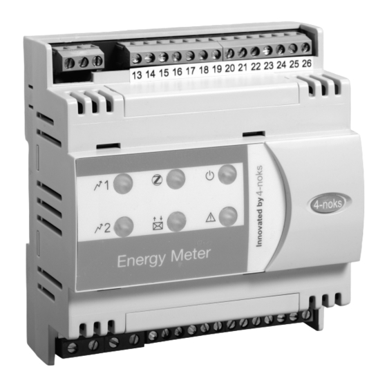
- Page 6 Observe VDEW guidelines and technical ■ connection requirements of the grid opera- tor. 2. Install energy meter on a mounting rail in the distri- bution panel, see fig. 1. Fig. 1 Energy meter Output control module...
- Page 7 Output control module installation and service instructions 131415 1617181920212223242526 +10 V Ctrl N L1 L2 L3 S 1 2 3 4 5 6 7 8 9 101112 Fig. 2 Output control module Connecting cable, max. 10 m long Energy meter...
- Page 8 230 V~ 13 14151617181920212223242526 1 2 3 4 5 6 N L1 L2 L3 7 8 9 101112 Fig. 3 From the main electricity meter To the RCD Current sensor with 3 m connecting cable (energy meter standard delivery) Energy meter...
- Page 9 7 8 9 101112 Fig. 4 From the main electricity meter To the RCD 3 current sensors with 3 m connecting cables (energy meter standard delivery) Energy meter Core assignment Connect current sensors in the correct position, as shown in fig. 4: ■...
-
Page 10: Power Supply
L1 N 13 14151617181920212223242526 N L1 L2 L3 S 1 2 3 4 5 6 7 8 9 101112 Fig. 5 Output control module Energy meter Fuse 16 A (slow) Power cable for output control module Power cable for energy meter... - Page 11 Fuse 16 A (slow) Power cable for energy meter Energy meter Power cable for output control module Connect the power cable to the energy meter as shown in fig. 5 and 6. Recommended power cable ■ In a 1-phase power circuit: 3-core with a cross-sec- tion of 2.5 mm...
-
Page 12: Switching The Power On
Commissioning Switching the power ON 1. Check whether all electrical connections have 3. Switch ON the power supply. The energy meter been correctly made. runs through an initialisation process. During this process, the red LED flashes for 20 seconds. 2. Commission the photovoltaic modules and inverter. -
Page 13: Fault Displays
– The set DHW temperature has been reached. During the initialisation process, the ener- Restore the energy meter to its delivered ■ gy meter establishes the maximum out- condition, see page 14. put of the immersion heater. If the maxi-... -
Page 14: Restoring The Energy Meter To Its Delivered Condition
Restoring the energy meter to its delivered condition If for example the initialisation process was unsuccess- ful. Fig. 8 Reset button 1. Remove the cover. 2. Press reset key The energy meter is restored to its delivered condi- tion and runs through an initialisation process. -
Page 15: Ordering Parts
Parts lists Ordering parts The following details are required when ordering parts: ■ Serial no. (see type plate ■ Position number of the part (from this parts list) -
Page 16: Parts List
Parts lists Parts list 0003 0001 0002 Fig. 9 Type plate... - Page 17 Parts lists Parts list (cont.) Pos. Part 0001 Current sensor 0002 Installation and service instructions 0003 Type plate...
- Page 18 Specification Specification Power supply 230 V, 50 Hz Power consumption 1.8 W Standby power consumption Y connection for measuring voltage 400 V 20 % ± 3-phase and neutral conductor Measuring accuracy, current Accuracy category 2 Dimensions...
-
Page 19: Declaration Of Conformity
Certificates Declaration of conformity We, Viessmann Werke GmbH & Co KG, D-35107 Allendorf, declare as sole responsible body that the product Energy meter complies with the following standards: ETSI EN 301 489-1 EN 61 010 ETSI EN 301 489-17 EN 61 326–1... - Page 20 Keyword index Commissioning............12 Installation..............6 Commissioning the energy meter......12 Connection – Current sensor............8 LED indicators............12 Current sensor............. 8 Mounting rail..............6 Declaration of Conformity...........19 Delivered condition.............14 Display elements............12 Output control module..........7 Distribution panel............6 Parts................15 Electrical connection Parts list..............15 –...