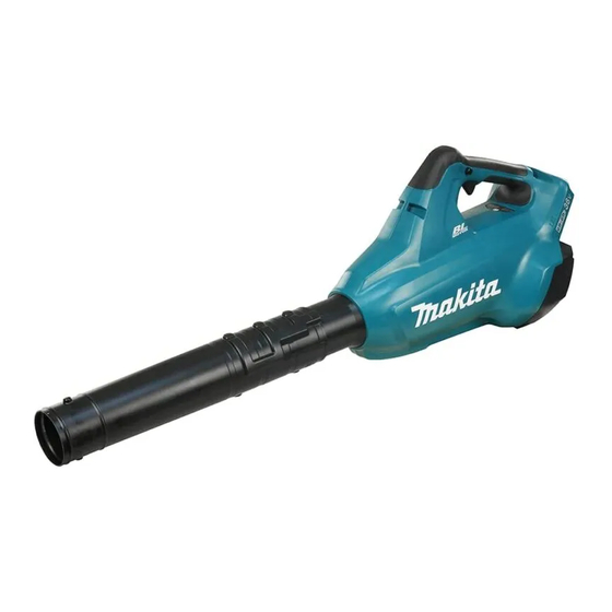
Makita XBU02 Repair Manual
Hide thumbs
Also See for XBU02:
- Instruction manual (37 pages) ,
- Instruction manual (25 pages) ,
- Instruction manual (17 pages)
Table of Contents
Advertisement
Quick Links
Advertisement
Table of Contents
Troubleshooting

Summary of Contents for Makita XBU02
- Page 1 REPAIR MANUAL XBU02...
-
Page 2: Necessary Repairing Tools
P 2/ 13 epair CAUTION: Repair the machine in accordance with "Instruction manual" or "Safety instructions". [1] NECESSARY REPAIRING TOOLS Code No. Description Use for 1R028 Bearing setting pipe 20-12.2 press-fitting Motor housing cover to Rotor 1R032 Bearing setting plate 8.2 holding Rotor when press fitting Motor housing cover 1R045 Gear extractor (large) - Page 3 P 3/ 13 epair [3] DISASSEMBLY/ASSEEMBLY [3] -1. Fan 110, Rotor (cont.) DISASSEMBLING (2) Separate Motor housing from Housing set L. (Fig. 2) Fig. 2 While paying attention not to loosen Switch section in Handle portion, separate Motor housing section from Housing set L. Switch section Fan 110 is removed from Housing set L...
- Page 4 P 4/ 13 epair [3] DISASSEMBLY/ASSEEMBLY [3] -1. Fan 110, Rotor (cont.) DISASSEMBLING (4) Remove Rotor from Motor housing. (Fig. 4) Fig. 4 1. Remove Flat washer 8 from the rotor shaft. 2. Loosen four 3x20 Tapping screws, and disassemble Cap from Motor housing so that Rotor can be removed from the cap side.
- Page 5 P 5/ 13 epair [3] DISASSEMBLY/ASSEEMBLY [3] -1. Fan 110, Rotor (cont.) Caution for Handling of Rotor When handling or storing multiple Rotors, be sure to keep a proper distance between Rotors as shown in Fig. 6 because Rotor has a strong magnetic force. Failure to follow this instruction could result in: •...
- Page 6 P 6/ 13 epair [3] DISASSEMBLY/ASSEEMBLY [3] -1. Fan 110, Rotor (cont.) ASSEMBLING (3) Assemble Fan 110 to the rotor shaft. (Fig. 9) Fig. 9 Motor housing 1. Fix Cap to Motor housing with four 3x20 Tapping screws. Flat washer 8 Rotor 2.
- Page 7 P 7/ 13 epair [3] DISASSEMBLY/ASSEEMBLY [3] -2. Fan Lock ON button ASSEMBLING Assemble Lock ON button. (Fig. 10) Fig. 10 1. Join Lock ON buttons and Compression spring 5 2. Assemble Lock ON button to Housing set L together while aligning their protrusions on Lock while fitting one protrusion to the cut ON buttons in the same direction.
- Page 8 P 8/ 13 epair [3] DISASSEMBLY/ASSEEMBLY [3] -3. Sub Controller DISASSEMBLING Disassemble Sub controller. (Fig. 11) Fig. 11 1. Remove Dial 28. 2. Disconnect the connector. Dial 28 Connector 3. Remove Sub controller by prying it off with a slotted screwdriver. Sub controller Note: Axis for Dial 28...
-
Page 9: Troubleshooting
P 9/ 13 epair [4] TROUBLESHOOTING Whenever you find any trouble in your machine, refer to this chapter first. Note in Repairing Fig. T -1 (1) Use a full charged battery which has the star mark. (Fig. T-1) (2) When Housing is disassembled, check the conditions of the electrical parts Star mark (Connectors, Lead wires, Switches, etc.), Rotor, Stator, Gear section, etc. -
Page 10: Check List For Troubleshooting
P 10/ 13 epair [4] TROUBLESHOOTING Check List for Troubleshooting Check the items from top of the following list. (Description of the item is referred to Circuit diagram in Fig. D-1.) After corrective action, return to the start of Trouble shooting and check again. Symptom Cause Corrective action... -
Page 11: Circuit Diagram
P 11/ 13 ircuit diagram Fig. D-1 Color index of lead wires' sheath Closed end Black splice Blue Poly olefin tube Brown Stator Flag connector Gray w/ lock Orange Straight connector Purple w/ poly olefin tube White Tape Yellow 28AWG Connector 14AWG 28AWG... -
Page 12: Wiring Diagram
P 12/ 13 iring diagram Fig. D-2 Wiring in Motor housing Route Lead wires of Startor through this groove. Motor housing Stator Fig. D-3 Wiring to Terminals Set Flag connectors to Terminals as shown below. Terminal of Terminal of Housing set R side Housing set L side Flag connector Flag connector... - Page 13 P 13/ 13 iring diagram Fig. D-4 Wiring in Housing set L Wiring to Sub controller Rib A Sub Controller Put Lead wires of Sub controller in this groove. Put Lead wires of Sub Controller under the top of rib A. Put connectors as shown in the figure.


