Table of Contents
Advertisement
Quick Links
INSTALLATION INSTRUCTIONS
R- -410A Single Package Electric Cooling
These instructions must be read and understood completely before attempting installation
DANGER, WARNING, CAUTION, and NOTE
The signal words DANGER, WARNING,
CAUTION, and NOTE are used to identify levels
of hazard seriousness. The signal word DANGER
is only used on product labels to signify an
immediate hazard. The signal words WARNING,
CAUTION, and NOTE will be used on product
labels and throughout this manual and other
manual that may apply to the product.
DANGER -- Immediate hazards which will result in
severe personal injury or death.
WARNING --Hazards or unsafe practices which
could result in severe personal injury or death.
CAUTION -- Hazards or unsafe practices which
may result in minor personal injury or product or
property damage.
NOTE -- Used to highlight suggestions which will
result in enhanced installation, reliability, or
operation.
TABLE OF CONTENTS
. . . . . . . . . . . . . . . . . . . . . . . . . . . .
. . . . . . . . . . . . . . . . . . . . . . . . . . . . . . . . .
. . . . . . . . . . . . . . . . . . . . . . . . . . . . .
. . . . . . . . . . . . . . . . . . . . . . . . . . . . . . . .
. . . . . . . . . . . . . . . . . . . . . . . . . . . . .
. . . . . . . . . . . . . . . . . . . . . . . . . . .
PAD324- -60
1 & 3 Phase
Safety Labeling and Signal Words
. . . . . . . . . . . . . . . . .
. . . . . . . . . . . . .
. . . . . . . . . . . . . . . . . . .
. . . . . . . . . . . . . . . . .
. . . . . . . . . . . . . . . . . .
. . . . . . . . . . . . .
. . . . . . . . . . . . . . . . . . .
. . . . . .
. . . . . . . . . . . . . .
. . . . . . . . . .
. . . . . . . . . .
. . . . . . . . . . . . . . . . . . .
. . . . . . . . . . . . . .
Signal Words in Manuals
The signal word WARNING is used throughout
this manual in the following manner:
WARNING
!
The signal word CAUTION is used throughout
this manual in the following manner:
CAUTION
!
Signal Words on Product Labeling
Signal words are used in combination with
colors and/or pictures or product labels.
WARNING
!
2
2
PERSONAL INJURY, AND/OR PROPERTY
2
DAMAGE HAZARD
2
Failure to carefully read and follow this warning
could result in equipment malfunction, property
3
damage, personal injury and/or death.
3
Installation or repairs made by unqualified
3
persons could result in equipment malfunction,
7
property damage, personal injury and/or death.
7
The information contained in this manual is
9
intended for use by a qualified service technician
11
familiar with safety procedures and equipped
11
with proper tools and test instruments.
11
Installation must conform with local building
codes and with the national Electrical Code
12
NFPA70 current edition or Canadian Electrical
13
Code part 1 CSA C.22.1.
15
22
25
27
513 01 3103 00
04/21/10
Advertisement
Table of Contents

Related Manuals for Carrier PAD324


Summary of Contents for Carrier PAD324
-
Page 1: Table Of Contents
INSTALLATION INSTRUCTIONS R- -410A Single Package Electric Cooling PAD324- -60 1 & 3 Phase These instructions must be read and understood completely before attempting installation Safety Labeling and Signal Words DANGER, WARNING, CAUTION, and NOTE The signal words DANGER, WARNING,... -
Page 2: Safety Considerations
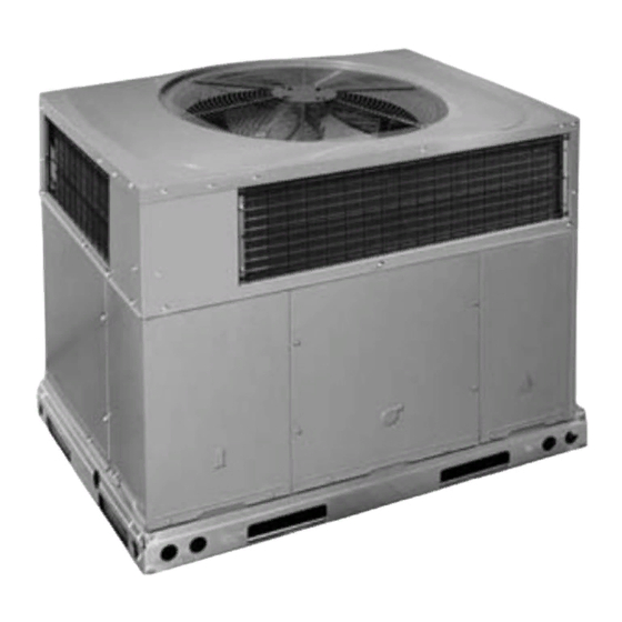
SAFETY CONSIDERATIONS FIG. 1 - - UNIT PAD3 Installation and servicing of this equipment can be hazardous due to mechanical and electrical components. Only trained and qualified personnel should install, repair, or service this equipment. Untrained personnel can perform basic maintenance functions such as cleaning and replacing air filters. -
Page 3: Step 3 - Provide Clearances
IMPORTANT: The gasketing of the unit to the roof curb is critical Training for operators of the lifting equipment should include, but not be limited to, the following: for a watertight seal. Install gasketing material supplied with the roof curb. Improperly applied gasketing also can result in air leaks 1. - Page 4 513 01 3103 00...
- Page 5 513 01 3103 00...
- Page 6 FIG. 6 - - ROOF CURB DIMENSIONS Dashed lines show cross support location for large basepan units. HVAC unit HVAC unit basepan base rails Sealing Gasket Roofcurb Anchor screw Wood nailer* Flashing field supplied Roofcurb* Insulation (field supplied) Roofing material field supplied Cant strip field supplied...
-
Page 7: Step 6 - Provide For Condensate Disposal
FIG. 7 - - RIGGING WEIGHTS CAUTION - NOTICE TO RIGGERS PRUDENCE - AVIS AUX MANIPULATEUR ACCESS PANELS MUST BE IN PLACE WHEN RIGGING. PANNEAUX D'ACCES DOIT ÊTRE EN PLACE POUR MANIPULATION. Use top skid as spreader bar. / Utiliser la palette du haut comme barre de répartition DUCTS MINIMUM HEIGHT: 36"... - Page 8 Select and size ductwork, supply--air registers, and return air WARNING grilles according to ASHRAE (American Society of Heating, Refrigeration, and Air Conditioning Engineers) recommendations. ELECTRICAL SHOCK HAZARD The unit has duct flanges on the supply-- and return--air openings Failure to follow this warning could result in personal injury or on the side of the unit.
-
Page 9: Step 8 - Install Electrical Connections
Step 8 — Install Electrical Connections side of the contactor. 4. Connect field L1 to black wire on connection 11 of the WARNING compressor contactor. 5. Connect field wire L3 to yellow wire on connection 13 of the ELECTRICAL SHOCK HAZARD compressor contactor. - Page 10 electric heat staging W1 and W2 (W2 and W3 on IFB). If room Transformer Protection thermostat has only one stage of supplemental heat, connect The transformer is of the energy--limiting type, however a direct white and violet wires shown in Fig. 10 to second stage heat field short will likely blow a secondary fuse.
-
Page 11: Pre--Start--Up
PRE- -START- -UP 1. Locate leak and make sure that refrigerant system pressure has been relieved and reclaimed from both high-- and WARNING low--pressure ports. 2. Repair leak following accepted practices. FIRE, EXPLOSION, ELECTRICAL SHOCK HAZARD NOTE: Install a filter drier whenever the system has been opened for repair. -
Page 12: Indoor Airflow Adjustments
Proceed as follows: shipped loose with vinyl caps and are located in the control box, near the interface fan board (IFB) (Fig. 11). 1. Remove caps from low-- and high--pressure service fittings. 2. Using hoses with valve core depressors, attach low-- and Single Cooling Fan Speed Set-up (Dehumidification feature high--pressure gauge hoses to low-- and high--pressure not used) -
Page 13: Cooling Sequence Of Operations
Table 3 – Color Coding for Indoor Fan Motor Leads Fig. 11 - - Interface Fan Board (IFB) Black = High Speed Orange = Med- -High Speed HIGH Red = Med Speed Pink = Med- -Low Speed Blue = Low Speed WARNING R13 C8 ELECTRICAL SHOCK HAZARD... - Page 14 Table 4 – Dry Coil Air Delivery* - - Horizontal and Downflow Discharge - - Unit PAD324- -60 WIRE EXTERNAL STATIC PRESSURE (IN. W.C.) UNIT MOTOR SPEED COLOR Blue Med-Low Pink Medium Med-High Orange 1009 High Black 1241 1167 1111...
-
Page 15: Wiring Diagram
Fig. 12 - - Connection Wiring Diagram 208/230- -1- -60 IF USED FIELD SUPPLY POWER 11 21 UNIT ONLY MAXIMUM WIRE 23 23 SIZE 2 AWG. COMPRESSOR PLUG EQUIP_GND COMP FOR WIRING WITH ELECTRIC HEATERS SEE SCHEMATIC ON HEATER ACCESSORY. GRN-YEL 230 200 GRN/YEL... - Page 16 Fig. 13 - - Ladder Wiring Diagram 208/230- -1- -60 DANGER: ELECTRICAL SHOCK HAZARD DISCONNECT POWER BEFORE SERVICING IF USED COMP TRAN SEE NOTE 7 24VAC FUSE P1-1 P1-2 P1-3 P1-4 P1-5 P1-6 P1-7 P2-1 P2-2 P2-3 P2-4 C,TRAN ACCESSORY ELECTRIC HEAT P4-1 P4-2...
- Page 17 Fig. 14 - - Connection Wiring Diagram 208/230- -3- -60 DANGER: ELECTRICAL SHOCK HAZARD DISCONNECT POWER BEFORE SERVICING SCHEMATIC IF USED 230-3-60 FIELD SUPPLY POWER UNIT ONLY FOR WIRING MAXIMUM WIRE WITH ELECTRIC SIZE 2 AWG. HEATERS SEE SCHEMATIC ON HEATER COMPRESSOR PLUG ACCESSORY.
- Page 18 Fig. 15 - - Ladder Wiring Diagram 208/230- -3- -60 DANGER: ELECTRICAL SHOCK HAZARD DISCONNECT POWER BEFORE SERVICING IF USED COMP TRAN SEE NOTE 7 24VAC C,IFB FUSE P1-1 P1-2 P1-3 IY1/YI P1-4 P1-5 IY2/DHI P1-6 IW2I P1-7 IW3I P2-1 P2-2 P2-3 P2-4...
- Page 19 Fig. 16 - - Connection Wiring Diagram 460- -3- -60 DANGER: ELECTRICAL SHOCK HAZARD DISCONNECT POWER BEFORE SERVICING SCHEMATIC IF USED 460-3-60 FOR WIRING WITH FIELD ELECTRIC HEATERS SUPPLY SEE SCHEMATIC POWER ON HEATER UNIT ONLY ACCESSORY. MAXIMUM WIRE SIZE 2 AWG. COMPRESSOR PLUG COMP EQUIP_GND...
- Page 20 Fig. 17 - - Ladder Wiring Diagram 460- -3- -60 DANGER: ELECTRICAL SHOCK HAZARD DISCONNECT POWER BEFORE SERVICING IF USED COMP 460V TRAN 460V SEE NOTE 7 24VAC FUSE P1-1 P1-2 P1-3 IY1/YI P1-4 P1-5 IY2/DHI P1-6 IW2I P1-7 IW3I P2-1 P2-2 P2-3...
- Page 21 Fig. 18 - - Cooling Charging Chart 513 01 3103 00...
-
Page 22: Maintenance
MAINTENANCE For longer life, operating economy, and continuing efficiency, clean accumulated dirt and grease from the blower wheel and To ensure continuing high performance, and to minimize the motor annually. possibility of premature equipment failure, periodic maintenance must be performed on this equipment. This cooling unit should be WARNING inspected at least once each year by a qualified service person. - Page 23 Fig. 20 - - Fan Blade Position FAN GRILLE MOTOR MOTOR SHAFT MAX DISTANCE BETWEEN TOP OF FAN GRILLE AND BOTTOM OF FAN BLADE “A” SIZE Outdoor Coil, Indoor Coil, and Condensate Drain Pan 2. Turn motor/grille assembly upside down on top cover to expose the fan blade.
- Page 24 3. Apply ohmmeter leads across switch. You should have WARNING continuity on a good switch. COPELAND SCROLL COMPRESSOR (R- -410A REFRIGER- EXPLOSION, SAFETY AND ENVIRONMENTAL HAZARD ANT) Failure to follow this warning could result in personal injury, The compressor used in this product is specifically designed to death or equipment damage.
-
Page 25: Troubleshooting
cracking) to occur in one year or more. When performing any LIQUID LINE FILTER DRIER service that may risk exposure of compressor oil to the roof, take The filter drier is specifically designed to operate with R--410A. appropriate precautions to protect roofing. Procedures which risk Use only factory--authorized components. - Page 26 Table 9 – Troubleshooting Chart SYMPTOM CAUSE REMEDY Power failure Call power company Fuse blown or circuit breaker tripped Replace fuse or reset circuit breaker Defective contactor, transformer, control relay, or high--pres- Replace component sure, loss--of--charge or low--pressure switch Compressor and outdoor fan will not start Insufficient line voltage Determine cause and correct Incorrect or faulty wiring...
-
Page 27: Start--Up Checklist
START- - UP CHECKLIST (Remove and Store in Job Files) I. PRELIMINARY INFORMATION MODEL NO.: SERIAL NO.: DATE: TECHNICIAN: II. PRESTART- -UP (Insert check mark in box as each item is completed) ( ) VERIFY THAT ALL PACKING MATERIALS HAVE BEEN REMOVED FROM UNIT ( ) REMOVE ALL SHIPPING HOLD DOWN BOLTS AND BRACKETS PER INSTALLATION INSTRUCTIONS ( ) CHECK ALL ELECTRICAL CONNECTIONS AND TERMINALS FOR TIGHTNESS ( ) CHECK THAT INDOOR (EVAPORATOR) AIR FILTER IS CLEAN AND IN PLACE...