Table of Contents
Advertisement
Quick Links
The Texas Instruments LM63635EVM evaluation module (EVM) helps designers evaluate the operation
and performance of the LM63635-Q1 buck regulator. The LM63635-Q1 is a family of easy-to-use
synchronous step-down DC/DC converters capable of driving up to 3.25 A of load current from an input
voltage of 3.5 V to 32 V. The LM63635EVM features a selectable output voltage of 3.3 V or 5 V and a
switching frequency of 400 kHz. See the
down Voltage Converter Data Sheet
The EVM options are found in
LM63635EVM
..........................................................................................................................
1
Setup
.....................................................................................................................
2
Operation
3
Performance Curves
.....................................................................................................................
4
Schematic
5
Board Layout
6
Bill of Materials
1
EVM Board Connections
2
EVM Card Edge Connections
3
Jumper Locations
....................................................................................................................
4
FRA Setup
5
Efficiency Without Input Filter AUTO Mode, V
6
Efficiency Without Input Filter AUTO Mode, V
SNVU617 – January 2020
Submit Documentation Feedback
LM636x5-Q1 3.5-V to 36-V, 1.5-A, and 2.5-A Automotive Step-
for additional features, detailed description, and available options.
Table
1.
Table 1. Device and Package Configurations
EVM
LM63635DQPWPRQ1
........................................................................................................
.................................................................................................................
.............................................................................................................
....................................................................................................
..............................................................................................
............................................................................................................
Copyright © 2020, Texas Instruments Incorporated
LM63635EVM EVM User's Guide
DEVICE
Contents
List of Figures
= 3.3V, f
= 400 KHz
OUT
SW
= 5 V, f
= 400 KHz
OUT
SW
User's Guide
SNVU617 – January 2020
FREQUENCY/OUTPUT
CURRENT
400 kHz / 3.25 A
.............................................
..............................................
LM63635EVM EVM User's Guide
3
6
6
7
8
12
3
4
4
5
6
6
1
Advertisement
Table of Contents

Related Manuals for Texas Instruments LM63635EVM


Summary of Contents for Texas Instruments LM63635EVM
-
Page 1: Device And Package Configurations
DC/DC converters capable of driving up to 3.25 A of load current from an input voltage of 3.5 V to 32 V. The LM63635EVM features a selectable output voltage of 3.3 V or 5 V and a switching frequency of 400 kHz. See the LM636x5-Q1 3.5-V to 36-V, 1.5-A, and 2.5-A Automotive Step-... -
Page 2: Table Of Contents
EVM Bottom Copper Layer List of Tables ..................Device and Package Configurations ....................BOM for LM63635EVM Trademarks All trademarks are the property of their respective owners. LM63635EVM EVM User’s Guide SNVU617 – January 2020 Submit Documentation Feedback Copyright © 2020, Texas Instruments Incorporated... - Page 3 This section describes the test points and connectors on the EVM and how to properly connect, set up, and use the LM63635EVM. Either the test points on the top of the board or the card edge connector can be used for connections. See...
- Page 4 GND, the part operates in auto mode where pulse frequency modulation (PFM) is engaged. 5V or 3.3V FPWM or Auto Output Voltage Selection Jumper Selection Jumper Figure 3. Jumper Locations LM63635EVM EVM User’s Guide SNVU617 – January 2020 Submit Documentation Feedback Copyright © 2020, Texas Instruments Incorporated...
- Page 5 TPGND1, TPGND2 - System power ground ^ _ /v‰µš š} ^ _ /v‰µš š} network analyzer network analyzer Signal Injection Figure 4. FRA Setup SNVU617 – January 2020 LM63635EVM EVM User’s Guide Submit Documentation Feedback Copyright © 2020, Texas Instruments Incorporated...
- Page 6 Figure 5. Efficiency Without Input Filter AUTO Mode, V = 5 V, f = 400 KHz AUTO Mode, V = 3.3V, f = 400 KHz LM63635EVM EVM User’s Guide SNVU617 – January 2020 Submit Documentation Feedback Copyright © 2020, Texas Instruments Incorporated...
-
Page 7: Lm63635Evm Schematic
Schematic www.ti.com Schematic Figure 7. LM63635EVM Schematic SNVU617 – January 2020 LM63635EVM EVM User’s Guide Submit Documentation Feedback Copyright © 2020, Texas Instruments Incorporated... -
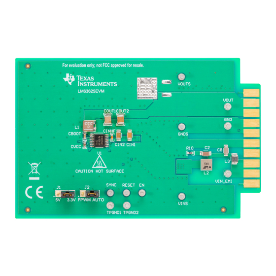
Page 8: Top View Of Evm
Board Layout www.ti.com Board Layout CAUTION Caution Hot surface. Contact may cause burns. Do not touch. Figure 8. Top View of EVM LM63635EVM EVM User’s Guide SNVU617 – January 2020 Submit Documentation Feedback Copyright © 2020, Texas Instruments Incorporated... -
Page 9: Bottom View Of Evm
Board Layout www.ti.com Figure 9. Bottom View of EVM Figure 10. EVM Top Copper Layer SNVU617 – January 2020 LM63635EVM EVM User’s Guide Submit Documentation Feedback Copyright © 2020, Texas Instruments Incorporated... -
Page 10: Evm Mid Layer One
Board Layout www.ti.com Figure 11. EVM Mid Layer One Figure 12. EVM Mid Layer Two LM63635EVM EVM User’s Guide SNVU617 – January 2020 Submit Documentation Feedback Copyright © 2020, Texas Instruments Incorporated... -
Page 11: Evm Bottom Copper Layer
Board Layout www.ti.com Figure 13. EVM Bottom Copper Layer SNVU617 – January 2020 LM63635EVM EVM User’s Guide Submit Documentation Feedback Copyright © 2020, Texas Instruments Incorporated... -
Page 12: Bom For Lm63635Evm
Bill of Materials www.ti.com Bill of Materials Table 2. BOM for LM63635EVM DESIGNATOR COMMENT DESCRIPTION MANUFACTURER PART NUMBER QUANTITY CAP, CERM, 0.22 µF, 16 V, CBOOT ±10%, X7R, AEC-Q200 Grade 1, Samsung CL10B224KO8VPNC 0603 CAP, CERM, 10 µF, 50 V, ±10%, X5R, AEC-Q200 Grade 1,... - Page 13 Bill of Materials www.ti.com Table 2. BOM for LM63635EVM (continued) DESIGNATOR COMMENT DESCRIPTION MANUFACTURER PART NUMBER QUANTITY CAP, CERM, 1 µF, 50 V, ±10%, Taiyo Yuden UMK316B7105KLHT X7R, AEC-Q200 Grade 1, 1206 CAP, CERM, 470 pF, 50 V, MuRata GRM155R71H471KA01D ±10%, X7R, 0402...
- Page 14 STANDARD TERMS FOR EVALUATION MODULES Delivery: TI delivers TI evaluation boards, kits, or modules, including any accompanying demonstration software, components, and/or documentation which may be provided together or separately (collectively, an “EVM” or “EVMs”) to the User (“User”) in accordance with the terms set forth herein.
- Page 15 www.ti.com Regulatory Notices: 3.1 United States 3.1.1 Notice applicable to EVMs not FCC-Approved: FCC NOTICE: This kit is designed to allow product developers to evaluate electronic components, circuitry, or software associated with the kit to determine whether to incorporate such items in a finished product and software developers to write software applications for use with the end product.
- Page 16 www.ti.com Concernant les EVMs avec antennes détachables Conformément à la réglementation d'Industrie Canada, le présent émetteur radio peut fonctionner avec une antenne d'un type et d'un gain maximal (ou inférieur) approuvé pour l'émetteur par Industrie Canada. Dans le but de réduire les risques de brouillage radioélectrique à...
- Page 17 www.ti.com EVM Use Restrictions and Warnings: 4.1 EVMS ARE NOT FOR USE IN FUNCTIONAL SAFETY AND/OR SAFETY CRITICAL EVALUATIONS, INCLUDING BUT NOT LIMITED TO EVALUATIONS OF LIFE SUPPORT APPLICATIONS. 4.2 User must read and apply the user guide and other available documentation provided by TI regarding the EVM prior to handling or using the EVM, including without limitation any warning or restriction notices.
- Page 18 Notwithstanding the foregoing, any judgment may be enforced in any United States or foreign court, and TI may seek injunctive relief in any United States or foreign court. Mailing Address: Texas Instruments, Post Office Box 655303, Dallas, Texas 75265 Copyright © 2019, Texas Instruments Incorporated...
- Page 19 TI products. TI’s provision of these resources does not expand or otherwise alter TI’s applicable warranties or warranty disclaimers for TI products. Mailing Address: Texas Instruments, Post Office Box 655303, Dallas, Texas 75265 Copyright © 2020, Texas Instruments Incorporated...