Table of Contents
Advertisement
Quick Links
Advertisement
Table of Contents

Related Manuals for Omega FMG70B Series


Summary of Contents for Omega FMG70B Series
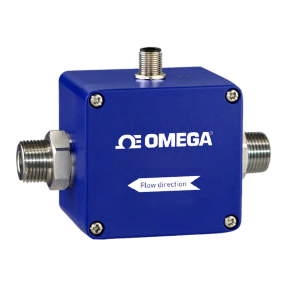
- Page 1 FMG70B Series Magnetic Inductive Flow Sensor...
- Page 2 - 2 - M-5575/0416...
-
Page 3: Table Of Contents
Table of contents page About this operating manual ..................4 Device description .....................5 1.1 Delivery, unpacking and accessories ..............5 1.2 Intended use ......................6 1.3 Exclusion of liability ....................6 Safety instructions .....................7 Construction and function ..................8 Installation of FMG70B ....................9 4.1 Installation instructions ....................9 4.2 Mounting ........................ -
Page 4: About This Operating Manual
• Thoroughly read and understand the information in the section "Safety instructions". If you have any problems or questions, please contact your supplier or contact us directly One Omega Drive, P.O. Box 4047 Stamford, CT 06907-0047 Tel: (203) 359-1660 e-mail: info@omega.com... -
Page 5: Device Description
Device description Device description The FMG70B series from Omega, is a non-contact flow sensor. The measurement is performed using magnetic induction and works without any moving parts. The FMG70B is used for measuring or metering water and aqueous solutions. The compact design and independence from the intake and discharge sections allows the FMG70B to be used under a variety of conditions. -
Page 6: Intended Use
Device description IMPORTANT! Use the type plate to check if the delivered unit corresponds to your order. In particular, for devices with electrical components, check to see if the correct power supply voltage is specified. Accessories: Connection cable with moulded M12x1 coupling socket. -
Page 7: Safety Instructions
In order to guarantee that the device operates safely, the operator must act competently and be conscious of safety issues. Omega provides support for the use of its products either personally or via relevant literature. The customer verifies that our product is fit for purpose based on our technical information. -
Page 8: Construction And Function
Construction and function Construction and function Components: Housing: The housing consists of aluminum die casting and has the IP65 degree of protection. Electrical connection: The electrical connection is made via 5-pin plug M12x1. Operation / flow indicator LED. ... -
Page 9: Installation Of Fmg70B
Installation of FMG70B Installation of FMG70B Before installing, check that the wetted materials of the device are suitable for the liquid being used ( § 9.2 "Materials table"). the equipment is switched off and is in a safe and de-energized state. ... -
Page 10: Mounting
Installation of FMG70B • Installation can occur in horizontal and vertical pipes. The flow sensor is only suitable for application in completely filled pipe systems. • As a matter of principle magnetic inductive flow sensors are widely independent from the flow profile. -
Page 11: Electrical Connection
Depending on the version, an analog output can be optionally connected. Connecting cable: Suitable connection cables with molded coupling socket are available in various lengths included in the range of Omega accessories. The shielding is already connected with the knurled nut. IMPORTANT! Shielding required! ... -
Page 12: Wirings
Electrical connection 5.1 Wirings Pinout: The pinout differs according to the chosen configuration of the device. Possible pinout: Pin 1: +U Pin 2: n. c. (not connected) / Analog U/I Pin 3: GND Pin 4: Frequency Pin 5: n. c. (not connected) / d. n. c. (do not connect) M12x1 ... -
Page 13: Commissioning And Measuring Mode
Commissioning and measuring mode Commissioning and measuring mode Before switching on the FMG70B for the first time, please follow the instructions in the following section. 6.1 Commissioning Check that the FMG70B has been installed correctly and that all screw connections are sealed. ... - Page 14 Commissioning and measuring mode FMG70B with analog output: According to the configuration of the FMG70B, the analog output provides a voltage or current signal. This signal is proportional to the measured flow. - 14 - M-5575/0416...
-
Page 15: Maintenance And Cleaning
Due to legal requirements placed on environmental protection and occupational safety and health and to maintain the health and safety of our employees, all units returned to Omega for repair must be free of toxins and hazardous substances. That also applies to cavities in the devices. -
Page 16: Disassembly And Disposal
Disassembly and disposal Disassembly and disposal CAUTION! Risk of injury! Never remove the device from a plant in operation. Make sure that the plant is shut down professionally. Before disassembly: Prior to disassembly, ensure that the equipment is switched off and is in a safe and de-energized state. ... -
Page 17: Technical Data
Technical data Technical data The technical data of customized versions may differ from the data in these instructions. Please observe the information specified on the type plate. 9.1 Characteristics FMG70B Type FMG71B FMG72B FMG73B Measurement device characteristics Measuring range 0.13…8 GPM 0.26…16 GPM 1.3…66 GPM Accuracy *... -
Page 18: Materials Table
Technical data Type FMG71B FMG72B FMG73B Process variables Medium to measure: Water and others conductive liquids > 50 μS/cm - Conductivity - Temperature 41…194 °F Ambient temperature 41…T °F ( § 9.4)* Inner diameter 0.39 in narrows to 0.39 in 0.79 in 0.16 in Nominal pressure... -
Page 19: Temperature Limits
Technical data 9.4 Temperature limits The maximum ambient temperature depends on the medium temperature and the version of the FMG70B. Technical changes reserved - 19 -... -
Page 20: Dimensions
Technical data 9.5 Dimensions FMG71B and FMG72B: ¾'' NPT only for FMG72B. The cross section of the FMG72B does not taper to 0.16 in. FMG73B: - 20 - M-5575/0416... - Page 21 For your notes For your notes Technical changes reserved - 21 -...
- Page 22 For your notes For your notes - 22 - M-5575/0416...
- Page 23 Technical changes reserved - 23 -...
- Page 24 M-5575/0416 - 24 - M-5575/0416...