
Related Manuals for ASROCK IMB-V2000


Summary of Contents for ASROCK IMB-V2000
- Page 1 IMB-V2000 User Manual Version 1.0 Published April 2021 Copyright©2021 ASRockInd INC. All rights reserved.
- Page 2 Version 1.0 Published April 2021 Copyright©2021 ASRockInd INC. All rights reserved. Copyright Notice: No part of this documentation may be reproduced, transcribed, transmitted, or translated in any language, in any form or by any means, except duplication of documentation by the purchaser for backup purpose, without written consent of ASRockInd Inc.
-
Page 3: Table Of Contents
Contents 1. Introduction ..............5 1.1 Package Contents ............5 1.2 Specifications ..............6 1.3 Motherboard Layout ............. 7 1.4 I/O Panel ..............9 2. Installation ..............11 2.1 Installing Memory Modules (DIMM) ....... 12 2.2 Expansion Slot ............... 13 2.3 Jumpers Setup ............... -
Page 4: Introduction
1. Introduction Thank you for purchasing ASRockInd IMB-V2000 motherboard, a reliable motherboard produced under ASRockInd’s consistently stringent quality control. It delivers excellent performance with robust design conforming to ASRockInd’s commitment to quality and endurance. In this manual, chapter 1 and 2 contains the introduction of the mother- board and step-by-step hardware installation guide. -
Page 5: Specifications
1.2 Specifications Form Dimensions Mini-ITX (6.7-in x 6.7-in) Factor AMD Ryzen™ Embedded V2000 SoC processors, up to 54W - IMB-V2000P (V2748, 2.9GHz, 35-54W) - IMB-V2000S (V2546, 3.0GHz, 35-54W) Processor - IMB-V2000M (V2718, 1.7GHz, 10-25W) System - IMB-V2000V (V2516, 2.1GHz, 10-25W) Chipset BIOS AMI SPI 256 Mbit... - Page 6 DisplayPort 3 x DP 1.2a, 1 x DP 1.4 Ethernet 1 x 1 Gigabit LAN, 1 x 2.5 Gigabit LAN 2 x USB 3.2 (Gen1), 2 x USB 2.0 Rear I/O Audio 2 (Mic-in, Line-out) 1 x COM (RS-232) 1 x COM (RS-232/422/485) DC Jack 1 (Screw Type) 2 x USB 3.2 Gen1 (1 x USB 3.2 Gen1...
-
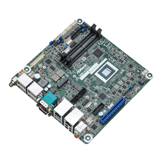
Page 7: Motherboard Layout
1.3 Motherboard Layout... - Page 8 1 : ATX Power Connector 2 : LVDS Panel Connector * eDP Connector (on the Backside of PCB) 3 : ATX/AT Mode Jumper (SIO_AT1) 4 : PCIe Isolation Jumper (PCIE_ISOLATION) 5 : BL1, BL2, BL3, BL4 6 : Backlight Power Select (LCD_BLT_VCC) (BKT_PWR1) 7 : Backlight Control Level (CON_LBKLT_CTL) (BLT_PWM1) 8 : Inverter Power Control Wafer (BLT_PWR1) 9 : Digital Input / Output Power Select (JGPIOPWR) (JGPIO_PWR1)
-
Page 9: I/O Panel
1.4 I/O Panel DisplayPort (DP0) USB 2.0 Ports (USB2H_2_3) DisplayPort (DP2) USB 3.2 Gen1 Ports (USB3_1_2) Serial Port (COM3)* 10 Serial Port (COM4)* LAN RJ-45 Port (LAN1)** 11 DisplayPort (DP3) LAN RJ-45 Port (LAN2)** 12 DisplayPort (DP1) Front Speaker (Lime) 13 DC Jack (DC_JACK1)*** Microphone (Pink) * This motherboard supports RS232/422/485 on COM3 port. - Page 10 *** Please refer to below pictures for DC jack specifications.
-
Page 11: Installation
Chapter 2: Installation This is a Mini-ITX form factor motherboard. Before you install the mother- board, study the configuration of your chassis to ensure that the mother- board fits into it. Pre-installation Precautions Take note of the following precautions before you install motherboard com- ponents or change any motherboard settings. -
Page 12: Installing Memory Modules (Dimm)
2.1 Installing Memory Modules (DIMM) This motherboard provides two DDR4 (Double Data Rate 4) SO-DIMM slots. Step 1. Unlock a DIMM slot by pressing the retaining clips outward. Step 2. Align a DIMM on the slot such that the notch on the DIMM matches the break on the slot. -
Page 13: Expansion Slot
2.2 Expansion Slots (PCI Express, SIM and M.2 Sockets) There is 1 PCI Express slot, 1 SIM socket and 3 M.2 sockets on this mother- board. PCIE Slot: The x8 lane width PCIE1 (PCIE 3.0 x8 slot) is used for PCI Ex- press expansion cards. - Page 14 Key-B M.2 Socket (M2_B1) Signal Name Signal Name +3V_M2B CONFIG_3 +3V_M2B Full_Card_Power_Off# W_DISABLE1_B# LP+1 WWAN_LED# LP-1 23 WAKE_ON_WAN# W_DISABLE2_B# UIM1_RESET M2B_RXN1_C UIM1_CLK M2B_RXP1_C UIM1_DATA +UIM1_PWR M2B_TXN1_C DEVSLP_REP M2B_TXP1_C SMB_CLK_M2B SMB_DATA_M2B M2B_RXN0 M2B_RXP0 M2B_TXN0_C PCIE_RST# M2B_TXP0_C B_CLKREQ#_R WAKE# M2B_CLK0N M2B_CLK0P SIM_DETECT_1 +3V_M2B +3V_M2B +3V_M2B...
-
Page 15: Jumpers Setup
2.3 Jumpers Setup The illustration shows how jumpers are setup. When the jumper cap is placed on pins, the jumper is “Short”. If no jumper cap is placed on pins, the jumper is “Open”. The illus- tration shows a 3-pin jumper whose pin1 and pin2 are “Short”... - Page 16 Panel Power Select (R_LVDD) 1-2 : R_LVDD: +3V 2-3 : R_LVDD: +5V (5-pin PNL_PWR1) 4-5 : R_LVDD: +12V (see p.7, No. 10) BL1, BL2, BL3, BL4 Open : Protect LCD_BLT_VCC (2-pin BL1) Short : No Protect LCD_BLT_VCC (see p.7 No. 5) Open : Protect R_LVDD (2-pin BL2) Short : No Protect R_LVDD...
- Page 17 CC_TALK_OUT1 (2-pin CC_TALK_OUT1) (see p.7, No. 16) ATX/AT Mode Jumper Open : ATX Mode Short : AT Mode (2-pin SIO_AT1) (see p.7, No. 3) PCIe Isolation Jumper (2-pin PCIE_ISOLATION) (see p.7, No. 4)
-
Page 18: Onboard Headers And Connectors
2.4 Onboard Headers and Connectors Onboard headers and connectors are NOT jumpers. Do NOT place jumper caps over these headers and connectors. Placing jumper caps over the headers and connectors will cause permanent damage of the motherboard! CPU Fan Connector Please connect the CPU fan +12V cable to the connector and... -
Page 19: Buzzer (Buzz2)
RESET (Reset Switch): Connect to the reset switch on the chassis front panel. Press the reset switch to restart the computer if the computer freezes and fails to perform a normal restart. PLED (System Power LED): Connect to the power status indicator on the chassis front panel. The LED is on when the system is operating. -
Page 20: Spdif Header
J1 Header This is an interface for front panel audio cable that allows (9-pin J1) convenient connection and (see p.7 No. 33) control of audio devices. 1. High Definition Audio supports Jack Sensing, but the panel wire on the chassis must support HDA to function correctly. Please follow the instruction in our manual and chassis manual to install your system. 2. - Page 21 LVDS Connector (40-pin LVDS1) (see p.7 No. 2) *eDP Connector (on the Backside of PCB) EDP1 (40-pin EDP1) Inverter Power Control Wafer (6-pin BLT_PWR1) (see p.7 No. 8) Signal Signal Signal Signal Signal Signal Name Name Name Name Name Name LCD_ LCD_ CON_...
- Page 22 Backlight & Amp Volume Control (7-pin BLT_VOL1) (see p.7 No. 19) Signal Signal Signal Signal Signal Signal Signal Name Name Name Name Name Name Name GPIO_ GPIO_ GPIO_ GPIO_ BLT_ PWRDN VOL_ VOL_ BLT_UP * To make the backlight level work properly, please make sure that the interval on button clicks is more than one second.
-
Page 23: Uefi Setup Utility
Chapter 3: UEFI SETUP UTILITY 3.1 Introduction This section explains how to use the UEFI SETUP UTILITY to configure your system. The UEFI chip on the motherboard stores the UEFI SETUP UTILITY. You may run the UEFI SETUP UTILITY when you start up the computer. -
Page 24: Navigation Keys
3.1.2 Navigation Keys Use < > key or < > key to choose among the selections on the menu bar, and use < > key or < > key to move the cursor up or down to select items, then press <Enter> to get into the sub screen. You can also use the mouse to click your required item. -
Page 25: Main Screen
3.2 Main Screen When you enter the UEFI SETUP UTILITY, the Main screen will appear and display the system overview. -
Page 26: Advanced Screen
3.3 Advanced Screen In this section, you may set the configurations for the following items: CPU Configuration, Chipset Configuration, Storage Configuration, Super IO Configuration, ACPI Configuration, USB Configuration and Trusted Com- puting. Setting wrong values in this section may cause the system to malfunction. Instant Flash Instant Flash is a UEFI flash utility embedded in Flash ROM. This convenient UEFI update tool allows you to update system UEFI ®... -
Page 27: Cpu Configuration
3.3.1 CPU Configuration Cool ‘n‘ Quiet Use this item to enable or disable AMD’s Cool ‘n’ Quiet technol- ogy. The default value is [Enabled]. Configuration options: [Enabled] ® and [Disabled]. If you install Windows OS and want to enable this function, please set this item to [Enabled]. Please note that en- abling this function may reduce CPU voltage and memory frequen- cy, and lead to system stability or compatibility issue with some memory modules or power supplies. -
Page 28: Chipset Configuration
3.3.2 Chipset Configuration Above 4G Decoding Enable or disable 64bit capable Devices to be decoded in Above 4G Address Space (only if the system supports 64 bit PCI decod- ing). Primary Graphics Adapter This item will switch the PCI Bus scanning order while searching for video card. - Page 29 eDP Panel BackLight Brightness Use this to adjust eDP panel backlight brightness. You are allowed to adjust this item only when CSM is disabled. Onboard HD Audio Select [Auto], [Enabled] or [Disabled] for the onboard HD Audio fea- ture. Onboard LAN 1 This allows you to enable or disable the Onboard LAN 1.
-
Page 30: Storage Configuration
3.3.3 Storage Configuration SATA Controller(s) Use this item to enable or disable the SATA Controller feature. SATA Mode Selection Use this to select SATA mode. Configuration options: [AHCI Mode] and [Disabled]. The default value is [AHCI Mode]. AHCI (Advanced Host Controller Interface) supports NCQ and other new features that will improve SATA disk performance but IDE mode does not have these advantages. -
Page 31: Super Io Configuration
3.3.4 Super IO Configuration COM1 Configuration Use this to set the parameters of COM1. COM2 Configuration Use this to set the parameters of COM2. COM3 Configuration Use this to set the parameters of COM3. Type Select Use this to select COM3 port type: [RS232], [RS422] or [RS485]. COM4 Configuration Use this to set the parameters of COM4. -
Page 32: Acpi Configuration
3.3.5 ACPI Configuration Suspend to RAM Select disable for ACPI suspend type S1. It is recommended to se- lect auto for ACPI S3 power saving. PCIE Devices Power On Use this to enable or disable the PCIE devices to turn on the sys- tem from power-soft-off mode. -
Page 33: Usb Configuration
3.3.6 USB Configuration USB Power Control Use this option to control USB power. There are two configuration options: [Always Enabled] and [Default Setting]. The default value is [Default Setting]. Please refer to below descriptions for the de- tails of these two options: [Always Enabled] - Enable USB power in S0/S3/S4/S5. [Default Setting] - Enable USB power in S0/S3, disable USB pow- er in S4/S5. -
Page 34: Trusted Computing
3.3.7 Trusted Computing Security Device Support Enable or disable BIOS support for security device. -
Page 35: Hardware Health Event Monitoring Screen
3.4 Hardware Health Event Monitoring Screen This section allows you to monitor the status of the hardware on your sys- tem, including the parameters of the CPU temperature, motherboard tem- perature, fan speed and voltage. CPU FAN1 Setting This allows you to set CPU FAN1’s speed. The default value is [Full On]. -
Page 36: Security Screen
3.5 Security Screen In this section you may set or change the supervisor/user password for the system. You may also clear the user password. Secure Boot Use this to enable or disable support for Secure Boot. -
Page 37: Boot Screen
3.6 Boot Screen This section displays the available devices on your system for you to con- figure the boot settings and the boot priority. Boot From Onboard LAN Use this to enable or disable Boot From Onboard LAN. Setup Prompt Timeout This shows the number of seconds to wait for the setup activation key. -
Page 38: Exit Screen
3.7 Exit Screen Save Changes and Exit When you select this option the following message, “Save configu- ration changes and exit setup?” will pop out. Select [OK] to save changes and exit the UEFI SETUP UTILITY. Discard Changes and Exit When you select this option the following message, “Discard changes and exit setup?”... -
Page 39: Software Support
Chapter 4: Software Support 4.1 Install Operating System ® ® This motherboard supports various Microsoft Windows operating systems: 10 64- bit. Because motherboard settings and hardware options vary, use the setup proce- dures in this chapter for general reference only. Refer your OS documentation for more information. -
Page 40: Amd Eyefinity Multidisplay Technology Setting
4.3 AMD Eyefinity Multidisplay Technology Setting Arrange Eyefinity Display Group 1. Arrange the display in a 4x1 or 2x2 configuration under Windows 10 Display set- ting. 2. Set up AMD Eyefinity with Quick Setup. 3. Click Eyefinity once AMD Radeon Settings opens. 4. Click Quick Setup to automatically create an AMD Eyefinity display group based on the current (default) display configuration.