U-Line 1 Class UHRE124 User Manual & Service Manual
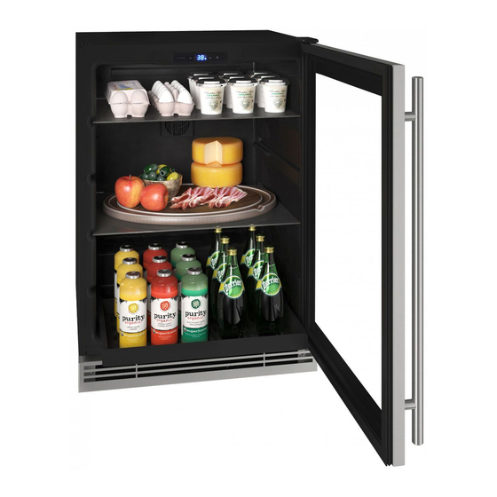
24” refrigerator
Hide thumbs
Also See for 1 Class UHRE124:
- User manual & service manual (51 pages) ,
- User manual & service manual (7 pages) ,
- User manual & service manual (48 pages)
Table of Contents
Advertisement
Quick Links
Advertisement
Table of Contents

Related Manuals for U-Line 1 Class UHRE124


Summary of Contents for U-Line 1 Class UHRE124
- Page 1 USER GUIDE & SERVICE MANUAL 1 Class UHRE124 24” Refrigerator ● ●...
-
Page 2: Table Of Contents
USER GUIDE & SERVICE MANUAL u-line.com Table of Contents Intro Safety Safety and Warning Disposal And Recycling Installation Environmental Requirements Electrical Cutout & Product Dimensions Side by Side Installation Anti-Tip Bracket General Installation Grille Installation Door Swing Door Adjust Interior Adjustments... -
Page 3: U-Line.com
® to preserve the right product, in the right place, at the right temperature. Since 2014, U-Line has been part of the Middleby family of brands. All products are designed, engineered, and assembled in Milwaukee, Wisconsin, USA, and select products are available worldwide. -
Page 4: Safety And Warning
USER GUIDE u-line.com Safety and Warning DANGER NOTICE This unit contains R600a (Isobutane) which is a Please read all instructions before installing, flammable hydrocarbon. It is safe for regular operating, or servicing the appliance. use. Do not use sharp objects to expedite defrosting. -
Page 5: Disposal And Recycling
USER GUIDE u-line.com Disposal and Recycling DANGER RISK OF CHILD ENTRAPMENT. Before you throw away your old refrigerator or freezer, take off the doors and leave shelves in place so children may not easily climb inside. If the unit is being removed from service for disposal,... -
Page 6: Environmental Requirements
USER GUIDE u-line.com Environmental Requirements This model is intended for indoor/interior applications only and is not to be used in installations that are open/ exposed to natural elements. This unit is designed to operate between 50°F (10°C) and 100°F (38°C). Higher ambient temperatures may reduce the unit’s ability to reach low temperatures and/or reduce... -
Page 7: Electrical
USER GUIDE u-line.com Electrical WARNING SHOCK HAZARD — Electrical Grounding Required. Never attempt to repair or perform maintenance on the unit until the electricity has been disconnected. Never remove the round grounding prong from the plug and never use a two-prong grounding adapter. -
Page 8: Cutout & Product Dimensions
23 ⁄ ” (608 mm) Cutout & Product Dimensions PREPARE SITE Your U-Line product has been designed for either free- standing or built-in installation. When built-in, your unit FRONT 34 ⁄ ” to 35 ⁄ ” 28” does not require additional air space for top, sides, or... -
Page 9: Side By Side Installation
USER GUIDE u-line.com Side-by-Side Installation 3. Place bracket over holes and attach to unit with two screws removed in step 2 using a T-25 Torx driver. Two units may be installed side-by-side. Tighten screws fully. Cutout width for a side-by-side installation is the cutout 4. -
Page 10: Anti-Tip Bracket
USER GUIDE u-line.com Anti-Tip Bracket Slide unit out so screws on top of unit are easily accessible. Remove the two screws from the opposite side of the hinge assembly using a T-25 Torx driver (see below). Place bracket over holes and attach to unit with two screws removed in step 2 using a T-25 Torx driver. -
Page 11: General Installation
USER GUIDE u-line.com General Installation INSTALLATION Plug in the power/electrical cord. LEVELING INFORMATION Gently push the unit into position. Be careful not Use a level to to entangle the cord or water and drain lines, if confirm the unit is applicable. -
Page 12: Grille Installation
Align cabinet and grille holes and secure, but do not over tighten grille screws (1). Note: When installing next to a 15” wide U-Line product, use the supplied spacers behind the grille. The 24” grille will now be on the same plane as the 15”... -
Page 13: Door Swing
USER GUIDE u-line.com Door Swing Wall 2-1/8" Min. (54 mm) 90° Door Swing Units have a zero clearance for the door to open 90°, when installed adjacent to cabinets. Stainless Steel models require 2-1/8" (54 mm) door clearance to accommodate the handle if installed next to a wall. -
Page 14: Door Adjust
USER GUIDE u-line.com Door Adjustments REVERSING THE DOOR Location of the unit may make it desirable to mount the HINGE COVER door on the opposite side of the cabinet. Hinge cover included with the literature bag is optional. The hinge hardware will be removed and reinstalled on the opposite side of the cabinet. - Page 15 USER GUIDE u-line.com Remove door by tilting forward and lifting door off Install top hinge and door: bottom hinge. Retain shoulder washers; they will be reused. Install hinge with longer straight edge aligned to Remove three screws from hinge holes on the outside edge of cabinet.
- Page 16 Free Standing Kit Te free standing kit is an optional accessory (ULAFREESTANDS), used when unit is freestanding - not built into a cabinet. Available at u-line.com. To install the kit: Remove grille (see GRILLE INSTALLATION section). Align front hole wit hole in shell accessory, hole in base, and hole in grille.
- Page 17 If the temperature displayed is different than selected, the unit is progressing towards the selected temperature. Time to reach set point varies based upon ambient temperature, temperature of product loaded, door openings, etc. U-Line recommends allowing the unit to reach set point before loading.
- Page 18 USER GUIDE u-line.com Control Operation CONTROL FUNCTION GUIDE FUNCTION COMMAND NOTES ON/OFF Press and release Unit will turn On or OFF Press and release to leave interior After 3 hours, factory default is restored; light will Leave interior light on light on for 3 hours;...
- Page 19 Typical Can Bottles and cans come in all shapes and sizes. When (135 mm) (123 mm) (12 oz) determining capacities U-Line uses the following sizes. Combinations of red and white bottles are used in Wine ® Captain Models and Beverage Centers.
-
Page 20: Interior Adjustments
USER GUIDE u-line.com Interior Adjustments NOTICE Make sure the shelves are inserted fully into the INTERIOR SHELVES unit. Removing and Installing Interior Shelves The edge strip toward the rear prevents cans and bottles from freezing against the cold evaporator. For models equipped with glass shelves having recessed shelf supports, remove the shelves as follows: 1. -
Page 21: Cleaning
USER GUIDE u-line.com Cleaning To clean integrated panels, use household cleaner per the cabinet manufacturer’s recommendation. Stainless Models Stainless door panels and handles can discolor when INTERIOR CLEANING exposed to chlorine gas, pool chemicals, saltwater or Disconnect power to the unit. - Page 22 USER GUIDE u-line.com NOTICE The drain pan was not designed to capture the water created when manually defrosting. To prevent water from overflowing the drain pan and possibly damaging water sensitive flooring, the unit must be removed from cabinetry. To defrost: 1.
-
Page 23: Cleaning Condenser
USER GUIDE u-line.com Cleaning Condenser INTERVAL - EVERY SIX MONTHS To maintain operational efficiency, keep the front grille free of dust and lint, and clean the condenser when necessary. Depending on environmental conditions, more or less frequent cleaning may be necessary. -
Page 24: Extended Non-Use
If the unit will be exposed to temperatures of 40°F (5°C) or less, the steps above must be followed. For questions regarding winterization, please call U-Line at 800.779.2547. CAUTION Damage caused by freezing temperatures is not covered by the warranty. - Page 25 For products installed and used for normal residential use, material cosmetic defects are included in this warranty, with coverage limited to 60 days from the date of original purchase. All service provided by U-Line under the above warranty must be performed by a U-Line factory authorized servicer, unless otherwise specified by U-Line.