Table of Contents
Advertisement
Quick Links
Advertisement
Table of Contents

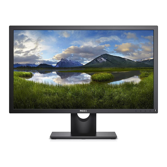
Summary of Contents for Dell P2018H
- Page 1 P2018H Service Service Service Simplified...
-
Page 2: Important Safety Notice
Important Safety Notice Proper service and repair is important to the safe, reliable operation of all DELL Company Equipment. The service procedures recommended by DELL and described in this service manual are effective methods of performing service operations. Some of these service operations require the use of tools specially designed for the purpose. - Page 3 1. Exploded view diagram with list of items Item Part NO. Description Quantity Q23G3155700005 BEZEL LOGO (27mm) Q05G00010650HF soundar_Mylar A34G4048-VH-1S0130 Bezel A33G1930-VH-1S0100 FUNCTION KEY A33G1931-VH-1L0200 POWER KEY KEPCHQZ1 KEY BOARD 750GBU195R10FBM0DL PANEL M195RTN01.0DF HF AUO Q52G18012780HF Mylar_power_BTM PLPCFA311AQD1 POWER BOARD Q52G18012770HF Mylar_power_TOP CBPCHTQDLQ8...
-
Page 4: Usb Board
USBHQZ2 USB BOARD P15G8299--3 Vesa bkt A34G4049-VH-2S0130 Rear_cover Q37G0585201101---1 Stand Q37G0602201101---1 Base 0D1G1030--7120 Screw D3X7 Pan W/C Nickel 0M1G2940-10225-CR3 Screw M4X10 Flat Nylok CR3 Black Zinc 0M1G3840--8120 Screw M4X8 Flat W/W Nickel 0Q1G2030--6120 Screw Q3X6 Flat Nickel 0M1G-930--8120 Screw M3X8 Pan Nickel QQ1G3530004120 Screw Q3X4 Flat Nickel Q01G6019--2... - Page 5 Disassembly Procedures Tools: 2 Power screwdrivers (φ=5mm, L=60mm); 1 small cross screwdriver; turnbuckle driver; Setting: Power screwdriver torque A=6 kgF.Cm Step Figure Tool Remark Unscrew the 4 screws by the Philips-head Screwdriver Press the button by hand to remove the hinge Remove the assy Base ass’y.
- Page 6 Tear out the four wires by hand. Unscrew the screws by the Philips-head Screwdriver. Torque=6±1kgf.cm Separate the key board and bezel. Remove the mylar by hand and remove the screws by the Philips-head Remove the Screwdriver to Mainboard Separate the power board and main board.
- Page 7 Main board Mainframe Panel Remove the screws. Torque=6±1kgf.cm by the Philips-head rear cover Screwdriver Separate the USB board and rear cover. Assembly Procedures...
- Page 8 lock the screws. Torque=6±1kgf.cm Assemble by the Philips-head the usb Screwdriver board assemble the USB board Stick the mylar by hand and lock the screws by the Philips-head Assemble Screwdriver to assemble the Mainboard power board and main board. Torque=6±1kgf.cm screw the screws by the Philips-head Assemble...
-
Page 9: Troubleshooting
screw the 4 screws by the Philips-head Assemble Screwdriver. the rear cover Torque=6±1kgf.cm Assemble stand ass’y. 4. Troubleshooting WARNING: Before you begin any of the procedures in this section, follow the Safety Instructions. Self-test Your monitor provides a self-test feature that allows you to check if your monitor is functioning properly. If your monitor and computer are properly connected but the monitor screen remains dark, run the monitor self-test by performing the following steps: 1. -
Page 10: Built-In Diagnostics
NOTE: This box also appears during normal system operation, if the video cable is disconnected or damaged. Turn off your monitor and reconnect the video cable; then turn on both your computer and the monitor. If your monitor remains dark after you reconnect the cables, check your video controller and computer. Built-in diagnostics Your monitor has a built-in diagnostic tool that helps you determine if any screen abnormality you experience is an inherent problem with your monitor, or with your computer and video card. - Page 11 1. Ensure that the screen is clean (no dust particles on the surface of the screen). 2. Unplug the video cable(s) from the back of the computer or monitor. The monitor then goes into the self-test mode. 3. Press and hold Button 1 on the front panel simultaneously for 5 seconds. A gray screen appears. 4.


