
Related Manuals for Nanotron Technologies swarm bee LE V2 DK+

Summary of Contents for Nanotron Technologies swarm bee LE V2 DK+
- Page 1 Technical Description swarm bee LE V2 DK+ User Guide Version: 1.0 Author: MBO swarm bee LE V2 DK+ User Guide NA-19-0358-0014...
- Page 2 Technologies GmbH reserves the right to make changes without further notice to the product to improve reliability, function or design. Nanotron Technologies GmbH does not assume any liability or responsibility arising out of this product, as well as any application or circuits described herein, neither does it convey any license under its patent rights.
-
Page 3: Table Of Contents
Technical Description swarm bee LE V2 DK+ User Guide Version: 1.0 Author: MBO Contents General Function ........................... 4 Technical Data ............................5 Block Diagram ............................5 Connector Configuration ........................6 Connector Description ........................7 4.1.1. Connector X1 ..........................7 4.1.2. Connectors X2, X3, X10 ......................7 4.1.3. -
Page 4: General Function
Technical Description swarm bee LE V2 DK+ User Guide Version: 1.0 Author: MBO General Function The swarm bee LE DK+ Board serves as a development tool for developing, testing and debugging software for Nanotrons swarm bee LE module. Several test points and connectors help to measure certain hardware parameters, such as RF output power or current consumption. -
Page 5: Technical Data
Technical Description swarm bee LE V2 DK+ User Guide Version: 1.0 Author: MBO Technical Data User and debugging interface 1………………..….. ST microcontroller embedded USART, 500 bps…2 Mbps User and debugging interface 2………………………..….. USB, converted to USART by FTDI chip, 115kbps Supply voltage via host connector ……………………..…………..........+3.1 V…+5.5 V Power consumption over host connector……………………………………..……………………….max. -
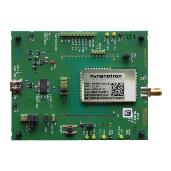
Page 6: Connector Configuration
Technical Description swarm bee LE V2 DK+ User Guide Version: 1.0 Author: MBO Connector Configuration Abbildung 4-1: Swarm bee LE DK+ Board, assembly and connector configuration Page 6 Doc ID NA-19-0358-0014 © 2019 All Rights Reserved... -
Page 7: 4.1 Connector Description
Technical Description swarm bee LE V2 DK+ User Guide Version: 1.0 Author: MBO Table 4-1: Swarm bee LE DK+ Board connector configuration Connector No. Description Type Default State RF port SMA type, 50 Ohm impedance assembled Swarm bee LE pins lead through Pin connector, 16 pole not assembled Swarm bee LE pins lead through... -
Page 8: Connector X4
Technical Description swarm bee LE V2 DK+ User Guide Version: 1.0 Author: MBO X2 Pin No. Swarm bee LE module pin no. GND - not connected to swarm bee LE Table 4-3: X3 pin assignment X3 Pin No. Swarm bee LE module pin no. GND - not connected to swarm bee LE GND - not connected to swarm bee LE Table 4-4: X10 pin assignment... -
Page 9: Connector X5
Technical Description swarm bee LE V2 DK+ User Guide Version: 1.0 Author: MBO 4.1.4. Connector X5 X5 is a standard Mini-USB B connector for connecting and powering the swarm bee LE DK+ Board from a host PC. 4.1.5. Connector X7 By bridging the Jumper X7 the autonomous mode for the swarm bee LE module can be disabled. -
Page 10: Connector X13
Technical Description swarm bee LE V2 DK+ User Guide Version: 1.0 Author: MBO 4.1.10. Connector X13 The supply voltage can be measured by the swarm bee LE module with an internal AD-Converter. Therefore a jumper bridge has to set over X13. With respect to the AD-converters internal supply voltage, the supply voltage of the swarm bee LE module is divided by 2.2273 for measuring. -
Page 11: Testpoints
Technical Description swarm bee LE V2 DK+ User Guide Version: 1.0 Author: MBO Testpoints The swarm bee LE DK+ Board provides testpoints for measurements. The testpoints are suited for connecting probes of oscillators or multimeters. Table 5-1: Testpoints pin assignment Testpoint Description Function... -
Page 12: Table 5-2: Description Of Operating Modes Shown In Figure 5-1
Technical Description swarm bee LE V2 DK+ User Guide Version: 1.0 Author: MBO Table 5-2: Description of operating modes shown in Figure 5-1 Short term Description Init 1 Wakeup after deep sleep Power on Switching on the DC/DC converter for supplying the RF power amp and nanoLOC Init 2 Initialisation of nanoLOC Calibration... -
Page 13: Schematic
Technical Description swarm bee LE V2 DK+ User Guide Version: 1.0 Author: MBO Schematic Figure 6-1: Swarm bee LE DK+ Board schematic © 2019 All Rights Reserved Doc ID: NA-19-0358-0014 Page 13... - Page 14 Technical Description swarm bee LE V2 DK+ User Guide Version: 1.0 Author: MBO Release History Date Authors Version Description 2019-07-04 nanotron Initial version Page 14 Doc ID NA-19-0358-0014 © 2019 All Rights Reserved...
- Page 15 If other agree to fully indemnify Nanotron Technologies GmbH for any personal medical devices are being used in the vicinity of wire- damages resulting from such improper use or sale.