Table of Contents
Advertisement
Quick Links
POWERCORE 30 INSTALLATION AND SETUP MANUAL
Ver 2.1
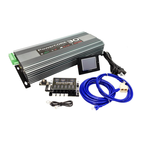
PowerCore 30
b a t t e r y m a n a g e m e n t s y s t e m
The PowerCore30 is a feature packed total battery management and automation
system developed specifically for 4wd vehicles, RV's and campers. With powerful,
compact all in one features, the system will deliver a full continuous 30 Amps of
charging power from solar panels, vehicle DC to DC input and AC power. It will
manage dual battery systems, disconnect loads when batteries are low, and
maintain house batteries during storage. View and control the PowerCore30 from
it's remote touch screen control panel, or download the PowerCore30 app and
connect your smart phone.
1
Advertisement
Table of Contents

Summary of Contents for AOR PowerCore 30
- Page 1 POWERCORE 30 INSTALLATION AND SETUP MANUAL Ver 2.1 PowerCore 30 b a t t e r y m a n a g e m e n t s y s t e m The PowerCore30 is a feature packed total battery management and automation system developed specifically for 4wd vehicles, RV's and campers.
- Page 2 POWERCORE 30 INSTALLATION AND SETUP MANUAL Ver 2.1 FEATURES ALL IN ONE compact 30 amp charger AC CHARGE - Charge from AC power source 30 amps DC_DC CHARGE - Charge from DC - DC vehicle power source 30 amps ...
-
Page 3: Safety And Warnings
Installation of the PowerCORE 30 should be carried out by a suitably qualified person. Always ensure that the PowerCORE 30 is installed and operated in a suitably ventilated location. A risk of explosion can occur due to dangerous gases being generated by batteries during normal operation. - Page 4 POWERCORE 30 INSTALLATION AND SETUP MANUAL Ver 2.1...
-
Page 5: Mounting Surface
PowerCORE30 . If your mounting location is tight in an enclosed compartment, ambient air temperature will rise very quickly if ventilation is insufficient. It is recommended that a ventilation 60mm hole be located under the PowerCORE 30 at the fan ventilation location to allow heat to be directed out of the compartment. - Page 6 POWERCORE 30 INSTALLATION AND SETUP MANUAL Ver 2.1 WIRING...
- Page 7 POWERCORE 30 INSTALLATION AND SETUP MANUAL Ver 2.1...
- Page 8 POWERCORE 30 INSTALLATION AND SETUP MANUAL Ver 2.1 AUTOMATION SWITCHING The PowerCORE 30 has 8 x internally auto resetting fused automation outputs that can switch DC loads . Maximum output of all outputs combined = 80amps Output 1 = Fused output 12A with dimming...
- Page 9 POWERCORE 30 INSTALLATION AND SETUP MANUAL Ver 2.1...
-
Page 10: Setting Up The System
POWERCORE 30 INSTALLATION AND SETUP MANUAL Ver 2.1 SETTING UP THE SYSTEM ENTERING SETUP To enter the setup area, press the settings button located on the home page. The screen will prompt for the entry of a password. The Setup password is : 6640 (ENTER) MAIN SETUP PAGE The main setup page is the entry point for setup of other functions - listed below. - Page 11 POWERCORE 30 INSTALLATION AND SETUP MANUAL Ver 2.1 NOTE : It is important to hide this option if there is no expansion module present, otherwise the system will regularly flash an error whilst attempting to find the nonexistent expansion module.
-
Page 12: Low Voltage Warning
POWERCORE 30 INSTALLATION AND SETUP MANUAL Ver 2.1 Pressing an ON button , will enable a particular output button to be visible on the switching page. Generally , and spare or unused outputs are set to OFF. To enter a label after turning a particular output on, press the black area of a blank label, or the label itself, and small keypad will pop up to enter the label with. - Page 13 VOLT SENSE option is selected, over time it is possible the PowerCORE 30 DC DC circuitry can be damaged by the constant switching on and off under load. In this case, the PowerCORE30 will not be covered under the manufacturers warranty.
- Page 14 Pressing the "SHOW" button will enable the tank monitoring feature on the system. The PowerCORE 30 system can display up to 4 x tanks. The tanks can be calibrated to various tank sensor types that can output a 0 to 5V signal.The FinScan PRS - 1000 sensor is supplied pre terminated with the correct RJ12 plug for instant connection.
- Page 15 POWERCORE 30 INSTALLATION AND SETUP MANUAL Ver 2.1 This Diagnostics button will access a diagnostic page that shows raw data to aid support and trouble shooting. This button is for factory use only . POWERCORE OVERIDE Located at the large green connector end of the charger, press the "Overide"...
- Page 16 POWERCORE 30 INSTALLATION AND SETUP MANUAL Ver 2.1 EXPANSION MODULE OVERIDE Located inside the expansion module, unscrew the plastic lid to reveal the fuses located inside. By moving the fuses for each circuit, the expansion module acts as a simple fuse box and applies fuse protected power to the connected DC load for emergency power.
-
Page 17: Specifications
POWERCORE 30 INSTALLATION AND SETUP MANUAL Ver 2.1 SPECIFICATIONS AC Input voltage range 220 - 240vAC - 50-60Hz Output Current 30 amp continuous Charge voltage 14.4v Float voltage 13.5v 10.5v - 28v DC - Low voltage or low current DC - DC Input voltage limitation due to cabling will cause a lower DC DC current output.