
Related Manuals for Acer Extensa 4120


Summary of Contents for Acer Extensa 4120
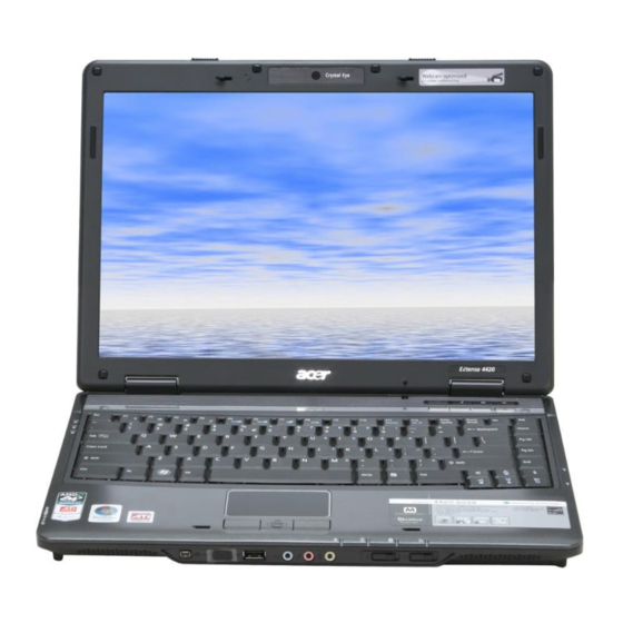
- Page 1 Acer TravelMate 4520 Notebook Computer Service Guide Service guide files and updates are available on the Acer CSD web site at http://csd.acer.com.tw PRINTED IN TAIWAN...
-
Page 2: Revision History
Revision History Refer to the table below for the updates made on this version of the TravelMate 4520 Notebook Computer Service Guide. Date Chapter Updates... - Page 3 Copyright Copyright © 2007 by Acer Incorporated. All rights reserved. No part of this publication may be reproduced, transmitted, transcribed, stored in a retrieval system, or translated into any language or computer language, in any form or by any means, electronic, mechanical, magnetic, optical, chemical, manual or otherwise, without the prior written permission of Acer Incorporated.
- Page 4 Conventions The following textual conventions are used in this service guide. SCREEN MESSAGES NOTE Gives additional information related to the current topic. WARNING Alerts you to any physical risk or system damage that might result from doing or not doing specific actions. CAUTION IMPORTANT Denotes actual messages that appear on screen.
- Page 5 Service Guide. For ACER-AUTHORIZED SERVICE PROVIDERS, your Acer office may have a DIFFERENT part number code to those given in the FRU list of this printed Service Guide. You MUST use the list provided by your regional Acer office to order FRU parts for repair and service of customer machines.
-
Page 7: Table Of Contents
Features 1 System Tour 1 Chapter 1 1 TravelMate Tour 5 Open Front View 5 Close Front View 6 Left View 7 Right View 8 Rear View 8 Base View 9 Status Indicators 10 Easy-launch Keys 11 Productivity Keys 12 Phoenix TrustedCore Setup Utility 13 System Utilities 13 Chapter 2 13... - Page 8 Table of Contents Removing the LED Board Removing the Fingerprint and Touchpad Boards Removing the Card Reader Board Removing the Bluetooth Board Removing the System Board Removing the Modem Board Removing the Speakers LCD Module Disassembly LCD Module Disassembly Flowchart 57 Removing the LCD Bezel Removing the Inverter Board Removing the LCD Module Hinges...
- Page 9 Test Compatible Components 113 Appendix B 113 Technical Specifications 117 Appendix C 1 117 Index 127 Table of Contents...
- Page 10 Table of Contents...
-
Page 11: Features
System Tour Features Your TravelMate 4520 is part of the Acer ProFile line of notebook computers. It provides superior computing performance and flexible usability in a classic matte black magnesium alloy casing. NOTE: The features listed in this section is for your reference only. The exact configuration of your TravelMate computer depends on the model purchased. -
Page 12: Display And Graphics
WPAN via Bluetooth LAN via a Gigabit Ethernet port (Wake-on-LAN ready) 56K ITU V.92 MDC 1.5 modem (PTT approved, Wake-on-Ring ready) Acer Video Conference solution for advanced Voice and Video over Internet Protocol (VVoIP) Built-in Acer Crystal Eye Optional Acer Bluetooth WLAN controller options Intel PRO/Wireless 3945ABG Network Connection (tri-mode 802.11a/b/g) -
Page 13: Power Subsystem
Kensington lock notch deters theft by letting you secure the notebook to a permanent object. Magnesium-alloy casing for a light-weight and reliable safeguard against physical damage. Data security Acer Bio-Protection solution provides network and data security by verifying an individual's true identity. Acer Empowering Technology (particularly the eDataSecurity and eLock features) Industry standard compliance Wi-Fi ACPI 3.0... -
Page 14: Physical Specifications
Operating system options Windows Vista™ Business Windows Vista Home Premium Windows Vista Home Basic System tools and utilities Acer Empowering Technology (eNet, ePower, eAudio , ePresentation, eDataSecurity, eLock, eRecovery, and eSettings Management) Acer Crystal Eye Acer Video Conference Manager Acer GridVista... -
Page 15: Travelmate Tour
Bluetooth and WLAN functions. Go to page 10 for more information. Function may vary base on actual notebook model. It can either be a 4-way scroll button or an Acer Bio-Protection fingerprint reader. Comfortable support area for your hands when you use the keyboard. -
Page 16: Close Front View
Close Front View Number Icon IEEE 1394 ports IR port Front USB 2.0 port Line-in jack Microphone-in jack Headphone jack Bluetooth switch WLAN switch Speakers Lid latch Item Connects to a IEEE 1394 devices. Interfaces with IR-aware (e.g. infrared printer, IR-aware computers and mobile phone). -
Page 17: Left View
Left View Number Icon Kensington lock notch Icon Item Optical disc drive (ODD) ODD access indicator * Lights up when a the optical drive is active . ODD eject button * Emergency eject hole * Ejects the ODD tray when the computer is turned off. USB 2.0 port 5-in-1 card reader slot * Item location varies depending on the drive model. -
Page 18: Right View
Right View Number Icon PC Card slot eject button PC Card slot USB 2.0 ports S-Video/TV-out port Ethernet port (RJ-45) VGA port DC-in jack Rear View Number Icon Ventilation slots Modem port (RJ-11) Item Ejects the PC Card from the slot. Accepts one Type II PC Card. -
Page 19: Base View
Base View Number Icon Battery lock Battery pack Battery release latch Ventilation slots Acer DASP pad Lower case cover Chapter 1 Item Secures the battery pack in position. Provides power to the computer. Releases the battery pack for removal. Enable the computer to stay cool, even after prolonged use. -
Page 20: Status Indicators
Status Indicators The computer has several status indicators for monitoring various system components and functions. Number Icon Hard drive activity Num Lock Caps Lock Power * Battery charge * Bluetooth * WLAN * * These indicators remain visible when the computer lid is closed. Indicator Flashes green when there is hard drive activity. -
Page 21: Easy-Launch Keys
Web browser * Mail * Programmable key Chapter 1 Indicator Press to launch the Acer Empowering Technology widgets. Press to launch the preferred Internet browser. Press to launch the preset E-mail application. Press to launch a customized program or function. -
Page 22: Productivity Keys
Press to launch the Windows Lock window. This enable users to protect the system from unauthorized access. If your computer is equipped with an Acer Bio-Protection fingerprint reader, you only need to swipe your finger to log into Windows again. Press to enable professional presentations without screen saver interruptions or system notifications. -
Page 23: Phoenix Trustedcore Setup Utility
System Utilities Phoenix TrustedCore Setup Utility Phoenix TrustedCore Setup Utility is a hardware configuration program built into your system's Basic Input/ Output System (BIOS). Since most systems are already properly configured and optimized, there is normally no need to run this utility. You will need to run this utility under the following conditions: When changing the system configuration including: Setting the system time and date... -
Page 24: Accessing The Setup Utility
Accessing the Setup Utility Turn on the computer. If the computer is already turned on, save your data and close all open applications, then restart the computer. During POST, press F2. If you fail to press F2 before POST is completed, you will need to restart the computer. The first page to be displayed will be the Information menu. -
Page 25: Navigating Through The Setup Utility
Navigating Through the Setup Utility Use the keys listed in the legend bar on the bottom of the Setup screen to work your way through the various menu and submenu screens of the Setup Utility. The table below lists these legend keys and their respective functions. -
Page 26: Setup Utility Menus
Setup Utility Menus The PhoenixBIOS Setup Utility has five menus for configuring the various system functions. These include: • Information • Main • Security • Boot • Exit Information The Information menu screen displays a summary of your computer hardware information. These information are necessary for troubleshooting and may be required when asking for technical support. - Page 27 Video Memory Displays the size of video memory detected during boot-up. Quiet Boot When enabled, the Acer logo screen appears during boot-up Network Boot When enabled, remote host with appropriate boot image can boot this computer. (Only works with an Ethernet device.)
- Page 28 Security The Security menu screen displays system passwords options to help safeguard and protect your computer from unauthorized use. Field Supervisor Password Is Indicates whether a supervisor password is in use (Set) or not (Clear). User Password Is Indicates whether a user password is in use (Set) or not (Clear). HDD Password Is Indicates whether an HDD password is in use (HDD Password Set) or not (Clear).
- Page 29 Setting a system password Note the following before you define a system password: • The maximum length of password contains eight alphanumeric characters—A - Z, 0 - 9, and ‘;’ (for a French keyboard). • System passwords are case-insensitive. • Password re-try is limited to three times.
- Page 30 To change a system password: Press to highlight an enabled password field, then press Enter. The password box appears. Type the original password, then press Enter. Type a new password, then press Enter. Retype the new password to verify the first entry, then press Enter. You will be prompted to save the new password.
- Page 31 Peel off the black tape near the DIMM slot to expose the SW1 dip switch. Locate the G41 pin. Short the G41 pin to clear all system passwords. Reinstall the memory modules and the lower case cover. Turn on the computer and press F2 during bootup to access the Setup Utility. 10.
- Page 32 Boot The Boot menu screen allows users to set the drive sequence in which Setup attempts to boot the operating system. By default, Setup searches for boot devices in the order shown in the screen below. To set the boot drive sequence: Press to select a bootable device.
- Page 33 Exit The Exit menu displays the several options on how to quit from the Setup Utility. Select any of the exit options then press Enter. Option Exit Saving Changes Exit Discarding Changes Load Setup Defaults Discard Changes Save Changes Chapter 2 Description Saves changes made and closes the Setup Utility.
-
Page 34: Bios Flash Utility
BIOS Flash Utility The BIOS flash memory update is required under the following conditions: When there are new versions of system programs When new hardware options are installed When the BIOS has been corrupted and you need to restore it BIOS Flash Precautions If you do not have a crisis recovery diskette at hand, create a Crisis Recovery Diskette in Windows XP of Vista before you use the flash utility. -
Page 35: Launch Manager
Launch Manager Launch Manager allows users to configure three of the easy-launch keys—Acer Empowering, Web browser, and Mail. To configure an easy-launch key: Select Start | All Programs | Launch Manager. Select which key to configure, then click the Add button opposite it. - Page 36 Chapter 2...
-
Page 37: Disassembly Tools
System Disassembly This chapter provides step-by-step instructions on how to disassemble the notebook computer for maintenance and troubleshooting purposes. Disassembly Tools In performing the disassembly process, you will need the following tools: Wrist-grounding strap and conductive mat for preventing electrostatic discharge Philips screwdriver Flat screwdriver Hex screwdriver... -
Page 38: System Screw List
System Screw List Listed below are the screw types used in this system, plus their corresponding part numbers. NOTE: The screws for the different components vary in size. During the disassembly process, group the screws with their corresponding components to avoid mismatches when putting back the components. Screw Type M2 x L8 BZN+NYLOK... -
Page 39: External Modules Disassembly
External Modules Disassembly External Modules Disassembly Flowchart Turn off computer and disconnect power cord EXpressCard SD dummy card dummy card Screw M2 x L8 BZN+NYLOK M2 x L4 BZN M2.5 x L8 BZN+NYLOK M2 x L4 BZN+NYLOK M3 x L4 M2 x L3 BZN+NYLOK M2 x L2.5 BZN+NYLOK Chapter 3... -
Page 40: Removing The Sd Dummy Card
Removing the SD Dummy Card Push against the card, as if you were pushing it further into the slot, letting the card spring out. Pull the SD dummy card out of its slot. Removing the PC Card Dummy Card Press the PC card slot eject button to pop it out, then press it again to eject the dummy card. Chapter 3... -
Page 41: Removing The Battery Pack
Pull the PC Card dummy card out of its slot. Removing the Battery Pack Turn the unit over with the base facing upward. Slide the battery lock to the unlock position. Slide and hold the battery release latch, then remove the battery pack from its bay. Chapter 3... -
Page 42: Removing The Lower Case Cover
Removing the Lower Case Cover Remove the screws securing the lower case cover. Step Type M2 x L8 BZN+NYLOK M2 x L4 BZN Pry the lower case cover from the main unit, then remove it. Removing the Memory Modules Push out the latches on both sides of the exterior DIMM slot (DM1). Quantity Color Black... -
Page 43: Removing The Wlan Board
Remove the memory module from its slot. Repeat steps 1 and 2 to remove the second memory module. Removing the WLAN Board Peel off the end of the bar code tape securing the WLAN antennas. Disconnect the antennas from the WLAN board, then move them away from the board. Chapter 3... -
Page 44: Removing And Dismantling The Hdd Assembly
Remove the screws securing the WLAN board. Step Type M2 x L4 BZN+NYLOK Remove the WLAN board from its slot (MINIC1). Removing and Dismantling the HDD Assembly Use the clear plastic tab and the black mylar tape to disconnect the HDD assembly from its connector (SATA). - Page 45 Remove the HDD assembly from the main unit. Remove the HDD rubber enclosure from the assembly. Remove the screws on the HDD module shielding. Step Type M3 x L4 Chapter 3 Quantity Color Silver 3 kgf-cm +/-15% Torque...
-
Page 46: Removing And Dismantling The Odd Assembly
Remove the shielding from the HDD module. Removing and Dismantling the ODD Assembly Remove the screw securing the ODD assembly to the main unit. Step Type M2.5 x L8 Use a plastic flat screwdriver to push the ODD assembly out of the main unit. Quantity Color Black... - Page 47 Pull the ODD assembly out of its bay. Remove the screws securing the ODD bracket. Step Type M3 x L4 Detach the ODD bracket from the module. Chapter 3 Quantity Color Silver 3 kgf-cm +/-15% Torque...
-
Page 48: Removing The Processor Cooling Fan
Removing the Processor Cooling Fan Disconnect the fan cable from its system board connector (FAN1). Remove the screws securing the cooling fan. Step Type M2 x L4 BZN+NYLOK Peel off the aluminum tape on the top edge of the cooling fan. Quantity Color Black... -
Page 49: Removing The Heat Sink
Remove the cooling fan from the main unit. Removing the Heat Sink Remove the screws securing the heat sink. Step Type M2 x L2.5 BZN+NYLOK Carefully pull the heat sink from the unit base, then remove it from the system board. Chapter 3 Quantity Color... -
Page 50: Removing The Processor
Removing the Processor Use a flat screwdriver to turn the processor socket lock to the counter-clockwise to the unlock position (note the unlock icon). Torque value: 3 kgf-cm +/-15% Hold the processor by its edges and remove it from its socket (U52). IMPORTANT: When installing a processor, note the golden arrow on the corner to make sure the processor is properly oriented over the socket. -
Page 51: Main Unit Disassembly
Main Unit Disassembly IMPORTANT: To prevent from scratching or damaging the LCD panel, cover it with a protective film before disassembling the main unit. Main Unit Disassembly Flowchart Main unit Keyboard Screw M2.5 x L8 BZN+NYLOK M2 x L4 BZN+NYLOK M2 x L3 BZN+NYLOK M2.5 x L12 BZN+NYLOK M2.5 x L4 BZN+NYLOK... -
Page 52: Removing The Middle Cover
Removing the Middle Cover Open the LCD panel completely to facilitate the easy removal of the middle cover. Use a plastic flat screwdriver to pry open the outer edge of the cover, then continue prying on the hinge sides until the cover is released from the U-case. Remove the middle cover from the main unit. -
Page 53: Removing The Lcd Module
Detach the top edge keyboard from the upper case, then turn it over the palmrest to gain access to the keyboard cable. Disconnect the keyboard cable from its system board connector (KB1) to completely detach the keyboard from the main unit. Removing the LCD Module Peel off the silver acetic tape protecting the LCD cable. - Page 54 Disconnect the LCD cable from its system board connector (LCD1). Peel off the masking tape securing the WLAN and internal microphone cables to the U-case. Disconnect the LCD cable from its system board connector (LCD1). Pull out the WLAN antennas from underneath the computer base, and then release them from their U-case latches.
- Page 55 Disconnect the internal microphone cable from its system board connector (INTMIC1). Release the internal microphone cable and the <main or aux??> WLAN antenna (white) from their U-case latches. Release the <main or aux??> WLAN antenna (black) from their U-case latches. Close the computer lid and turn the unit over to the base side.
- Page 56 10. Remove the lower case screws securing the LCD module. Step Type M2.5 x L8 BZN+NYLOK 11. Turn the unit right side up and open the notebook lid again. 12. Remove the hinge screws securing the LCD module. Step Type M2.5 x L12 BZN+NYLOK 13.
-
Page 57: Removing The Upper Case
Removing the Upper Case Disconnect the following system cables from their board connectors. Notebook lid cable (LID1) Fingerprint board cable (FP1) Touchpad board cable (TPAD1) Chapter 3... - Page 58 LED board cable (LEDB1) Turn the unit over to the base side. Remove the lower case screws securing the upper case. Step Type M2.5 x L4 BZN+NYLOK Turn the unit over again and remove the single top upper case screw. Step Type M2.5 x L4 BZN+NYLOK...
-
Page 59: Removing The Led Board
Detach the upper case from the lower case. Removing the LED Board Locate the LED board on the upper case underside. Remove the screw securing the LED board. Step Type M2 x L3 BZN+NYLOK Peel off the LED board cable from the upper case, then grasp the LED board and pull the cable through its upper case opening. -
Page 60: Removing The Fingerprint And Touchpad Boards
Removing the Fingerprint and Touchpad Boards Disconnect the fingerprint board cable. Detach the fingerprint board cable from the upper case. Disconnect the touchpad board cable. Detach the fingerprint board cable from the upper case. Chapter 3... - Page 61 Remove the screws securing the fingerprint board bracket. Step Type M2 x L4 BZN+NYLOK Detach the fingerprint board bracket from the upper case. Remove the screws securing the fingerprint board. Step Type M2 x L4 BZN+NYLOK Chapter 3 Quantity Color Silver 1.6 kgf-cm +/-15% Quantity...
-
Page 62: Removing The Card Reader Board
Detach the fingerprint board from its bracket. Carefully pry loose the touchpad board from the upper case to detach it. CAUTION: The touchpad board is glued to the upper case. Remove the touchpad board only if it is defective. Removing the Card Reader Board Remove the screws securing the card reader board to the system board. -
Page 63: Removing The Bluetooth Board
Detach the card reader board from its connector (CRB1). Removing the Bluetooth Board Disconnect the Bluetooth board cable from its system board connector (BLUE1). Detach the Bluetooth board from the left speaker. Chapter 3... -
Page 64: Removing The System Board
Removing the System Board Disconnect the speaker cable from its system board connector (SPKR1). Remove the single screw securing the system board to the lower case. Step Type M2 x L4 BZN+NYLOK Detach the system board from the upper case, then turn it over to gain access to the modem board. Proceed to the next section for instructions on how to remove the modem board. -
Page 65: Removing The Modem Board
Removing the Modem Board Remove the screws securing the modem board. Step Type M2 x L3 BZN+NYLOK Remove the modem board from its system board connector (MDC1), then disconnect the modem cable from the board. Removing the Speakers Remove the screws securing the speakers. Step Type M2 X L2 NI... - Page 66 Release the speaker cable from its lower case latches. Remove the speakers from the lower case. Chapter 3...
-
Page 67: Lcd Module Disassembly
LCD Module Disassembly LCD Module Disassembly Flowchart Screw M2 x L4 BZN+NYLOK M2 x L3 BZN+NYLOK M2.5 x L6 BZN+NYLOK M2.5 x L5 BZN+NYLOK M2.5 x L3 BZN+NYLOK Chapter 3 LCD module LCD bezel (Jx6) LCD panel LCD chassis (Lx4, Dx2) LCD panel brackets Inverter board (Fx6) -
Page 68: Removing The Lcd Bezel
Removing the LCD Bezel Remove the rubber pads securing the LCD bezel screws. Remove the screws securing the LCD bezel. Step Type M2.5 x L6 BZN+NYLOK Carefully pry the LCD bezel open and remove it from the LCD module. Quantity Color Black 3 kgf-cm +/-15%... -
Page 69: Removing The Inverter Board
Removing the Inverter Board Remove the screws on the lower edge of the LCD panel. Step Type M2 x L3 BZN+NYLOK Turn the board over and disconnect the 2P cable. Disconnect the inverter cable from the board. Chapter 3 Quantity Color Black 1.6 kgf-cm +/-15%... -
Page 70: Removing The Lcd Module Hinges
Removing the LCD Module Hinges Remove the screws securing the LCD module hinges. Step Type M2.5 x L5 BZN+NYLOK Remove the LCD module hinges from the LCD chassis. Removing the LCD Panel Disconnect the CCD board cable. Quantity Color Black 3 kgf-cm +/-15% Torque Chapter 3... -
Page 71: Removing The Lcd-Ccd Cable
Release the WLAN antennas from the left and right LCD brackets. Remove the LCD panel from its chassis. Removing the LCD-CCD Cable Peel off the LCD-CCD cable from the bottom edge of the LCD panel. Chapter 3... -
Page 72: Removing The Lcd Panel Brackets
Detach the adhesive tab on the cables’s LCD connector, then disconnect the cable from the LCD panel PCB. Removing the LCD Panel Brackets Remove the screws securing the LCD panel brackets. Step Part Number and Type M2 x L3 BZN+NYLOK Quantity Color Silver... -
Page 73: Removing The Internal Microphone And The Ccd Board
Removing the Internal Microphone and the CCD Board Peel off the aluminum foil tabs and acetic tape securing the microphone cable. Carefully remove the internal microphone from the LCD chassis. Remove the CCD board from the LCD chassis. Chapter 3... -
Page 74: Removing The Wlan Antennas
Removing the WLAN Antennas Peel off the aluminum foil tabs securing the WLAN antennas. Carefully detach the WLAN antenna from the LCD chassis. Chapter 3... -
Page 75: Hardware Diagnostic Procedure
Hardware Diagnostic Procedure IMPORTANT: The diagnostic tests described in this chapter are only intended to test Acer products. Non-Acer products, prototype cards, or modified options can give false errors and invalid system responses. -
Page 76: System Check Procedures
System Check Procedures External Diskette Drive Check Do the following to isolate the problem to a controller, driver, or diskette. A write-enabled, diagnostic diskette is required. IMPORTANT: Make sure that the diskette does not have more than one label attached to it. Multiple labels can damage to the drive. -
Page 77: Memory Check
Memory Check Memory errors might stop system operations, display error messages, or cause the system to hang up. Make sure that the DIMM is properly installed in its slot. A loose connection can cause an error. If the DIMM connection is correct, run the Doagmpstotics Test. Boot from the diagnostics diskette and start the Doagmpstotics program. -
Page 78: Touchpad Check
Check the Battery Pack Check the battery pack via the OS control and by checking the actual battery pack. Using the OS control: Open the Power Management setting in the Windows Control Panel screen. On the Power Meter tab, confirm that the Current Power Source and Total Battery Power Remaining parameters are correct. -
Page 79: Post Error Indicators
POST Error Indicators When POST detects a system failure, it either displays a POST error message, or emits a series of beep codes. POST Error Message Whenever a non-fatal error occurs during POST, an error message describing the problem appears onscreen. These text messages are displayed in normal video (white text on black background). - Page 80 Error Message List Error Message Failure Fixed Disk Stuck Key Keyboard Error Keyboard Controller Failed Keyboard locked - Unlock key switch Monitor type does not match CMOS - Run Setup Shadow RAM Failed at offset: nnnn System RAM Failed at offset: nnnn Extended RAM Failed at offset: nnnn System battery is dead - Replace and run Setup...
- Page 81 Error Message DMA Test Failed Software NMI Failed Fail-Safe Timer NMI Failed Device Address Conflict Allocation Error for device Failing Bits: nnnn Fixed Disk n Invalid System Configuration Data I/O device IRQ conflict Operating system not found System Error – No Beep Error Message No beep, power indicator turns off and the LCD screen is blank.
-
Page 82: Post Beep Codes
Error Message No beep, power indicator turns on, the LCD screen is blank, but you can view POST when connected to an external CRT. No beep, power indicator turns on and a blinking cursor appears on screen during POST. No beep during POST but system runs correctly. - Page 83 Code Chapter 4 Beeps 1-3-4-3 RAM failure on data bits xxxx of low byte of memory bus Enable cache before system BIOS shadow 1-4-1-1 RAM failure on data bits xxxx of high byte of memory bus Test CPU bus-clock frequency Initialize Phoenix Dispatch Manager Warm start shut down Shadow system BIOS ROM...
- Page 84 Code Beeps Display possible high address for UMB recovery Display error messages Check for configuration errors Check for keyboard errors Set up hardware interrupt vectors Initialize coprocessor if present Disable onboard Super I/O ports and IRQs Late POST device initialization Detect and install external RS232 ports Configure non-MCD IDE controllers Detect and install external parallel ports...
- Page 85 Code Chapter 4 Beeps Scan for F2 key stroke Enter SETUP Clear Boot flag Check for errors POST done—prepare to boot operating system One short beep before boot Terminate QuietBoot (optional) Check password (optional) Prepare Boot Initialize DMI parameters Initialize PnP Option ROMs Clear parity checkers Display MultiBoot menu Clear screen (optional)
- Page 86 Code Beeps Initialize interrupt vectors Initialize Run Time Clock Initialize video Initialize System Management Mode Output one beep before boot Boot to Mini DOS Clear Huge Segment Boot to Full DOS POST Routine Description Chapter 4...
-
Page 87: Index Of Symptom-To-Fru Error Message
Index of Symptom-to-FRU Error Message NOTE: If the symptom or error for your problem condition is not listed in this section, refer to the “Undetermined Problems” section on page 81. LCD-related Symptoms Symptom/Error LCD backlight doesn't work LCD is too dark LCD brightness cannot be adjusted LCD contrast cannot be adjusted Unreadable LCD screen... - Page 88 Memory-related Symptom Symptom / Error Memory count (size) appears different from actual size. Audio-related Symptoms Symptom / Error In Windows multimedia programs, no sound comes from the computer. Internal speakers emit noise or emit no sound. Power Management-related Symptoms Symptom / Error The system will not enter hibernation mode.
- Page 89 I/O-related Symptoms Symptom / Error System configuration values does not match the installed devices. External display does not work correctly. USB does not work correctly Print problems Keyboard (one or more keys) does not work. Touchpad does not work. Internal modem does not work correctly. Chapter 4 Action in Sequence Run the Setup Utility, then press F9 to load the system...
-
Page 90: Intermittent Problems
Intermittent Problems Intermittent system hang problems can be caused by a variety of reasons that have nothing to do with a hardware defect, such as cosmic radiation, electrostatic discharge, or software errors. FRU replacement should be considered only when a recurring problem exists. When analyzing an intermittent problem, do the following: Run the advanced diagnostic test for the system board in loop mode at least ten times. -
Page 91: Undetermined Problems
Follow these procedures to isolate the failing FRU (do not isolate non-defective FRU). Shut down the computer. Visually check the failing FRU for damage. If any problems are found, replace the FRU. Remove or disconnect all the following devices: Non-Acer devices Printer, mouse, and other external devices Battery pack Hard disk drive... -
Page 92: Online Support Information
This section describes online technical support services available to help you repair your TravelMate notebook. If you are a distributor, dealer, ASP or TPM, please refer your technical queries to your local Acer branch office. Acer Branch Offices and Regional Business Units may access our website at http://global.acer.com/ support/index. -
Page 93: System Block Diagram
Chapter 5 System Block Diagram and Board Layout System Block Diagram Chapter 5... -
Page 94: System Board Layout
System Board Layout This section shows the top and bottom layout of the TravelMate 4520 system board. Top View Item Code LCD1 LCD-CCD cable connector LID1 Notebook lid connector PC card slot RTC1 CMOS battery (RTC battery) CRB1 Card reader board connector SPKR1 Speaker cable connector BLUE1... -
Page 95: Bottom View
Bottom View Item Code MDC1 Modem board connector BAT1 Battery pack connector ODD1 Optical drive connector soDIMM slots ATI M690G chipset MINIC1 WLAN board slot SATA1 Hard drive connector Processor socket FAN1 Fan cable connector Chapter 5 Description... -
Page 96: System Switch
System Switch If you have enabled the Password on Boot field and you forget the supervisor password, you will not be able to boot up the computer. Your TravelMate notebook has a hardware pin (G41) for clearing a lost supervisor password. -
Page 97: Fru (Field Replaceable Unit) List
Guide. For ACER AUTHORIZED SERVICE PROVIDERS, your Acer office may have a DIFFERENT part number code from those given in the FRU list of this printed Service Guide. You MUST use the local FRU list provided by your regional Acer office to order FRU parts for repair and service of customer machines. -
Page 98: Aspire 5910 Exploded Diagram
Aspire 5910 Exploded Diagram Chapter 6... -
Page 99: Travelmate 4520 Fru List
TravelMate 4520 FRU List Category Audio-related Boards Chapter 6 Part Name and Description Acer Part No. - Page 100 Category Part Name and Description Acer Part No. Cables Chapter 6...
- Page 101 Category Part Name and Description Acer Part No. Hard Disk Drive Chapter 6...
- Page 102 Category Part Name and Description Acer Part No. Keyboard Chapter 6...
- Page 103 Category Part Name and Description Acer Part No. Keyboard (TM) LCD Panel Chapter 6...
- Page 104 Category Part Name and Description Acer Part No. Mechanical parts Chapter 6...
- Page 105 Category Part Name and Description Acer Part No. Memory Optical Disc Drive Chapter 6...
- Page 106 Category Part Name and Description Acer Part No. Power-related Processor Chapter 6...
- Page 107 Category Part Name and Description Acer Part No. Screws Miscellaneous Chapter 6...
- Page 108 Category Part Name and Description Acer Part No. Audio-related Boards Chapter 6...
- Page 109 Category Part Name and Description Acer Part No. Cables Chapter 6...
- Page 110 Category Part Name and Description Acer Part No. Hard Disk Drive Chapter 6...
- Page 111 Category Part Name and Description Acer Part No. Keyboard Chapter 6...
- Page 112 Category Part Name and Description Acer Part No. Keyboard (TM) LCD Panel Chapter 6...
- Page 113 Category Part Name and Description Acer Part No. Mechanical parts Chapter 6...
- Page 114 Category Part Name and Description Acer Part No. Memory Optical Disc Drive Chapter 6...
- Page 115 Category Part Name and Description Acer Part No. Power-related Processor Chapter 6...
- Page 116 Category Part Name and Description Acer Part No. Screws Miscellaneous Chapter 6...
-
Page 117: Travelmate 4520 Series Model Configurations
TravelMate 4520 Series Model Configurations This chapter provides features summary for each of the four TravelMate 4520 Series computer model configurations. Model A (TravelMate 4220) System Internal Part Number: 91.4U101.001G System Board Internal Part Number: 55.4U101.001G/55.4U101.M01G Component Processor Sempron 64 3600+ 25W F North bridge ATI RS690M South bridge... - Page 118 Model B (TravelMate 4520) System Internal Part Number: 91.4U101.002G System Board Internal Part Number: 55.4U101.001G/55.4U101.M01G Component Processor Turion 64 X2 TL56 rev.G North bridge ATI RS690M South bridge ATI SB600 LCD module AUO 14.1" WXGA non-glare Memory Nanya DDRII 667 512MB*2 NT512T64UH8B0FN-3C KN.51203.032 Hard disk drive WD 2.5"...
- Page 119 Model C (TravelMate 4520) System Internal Part Number: 91.4U101.003G System Board Internal Part Number: 55.4U101.011G/55.4U101.M02G Component Processor Turion 64 X2 TL64 rev.G North bridge ATI RS690M South bridge ATI SB600 LCD module Samsung 14.1” WXGA LTN141W3-L01-G GLARE 16MS, 200NITS Memory Hynix DDRII 667 1GB HYMP512S64CP8-Y5 Hard disk drive WD 2.5"...
- Page 120 Model D (TravelMate 4520) System Internal Part Number: 91.4U101.004G System Board Internal Part Number: 55.4U101.011G/55.4U101.M02G Component Processor Turion 64 X2 TL66 rev.G North bridge ATI RS690M South bridge ATI SB600 LCD module Samsung 14.1” WXGA LTN141W3-L01-G GLARE 16MS, 200NITS Memory Samsung DDRII 667 1GB*2 M470T2953EZ3-CE Hard disk drive HGST 160 GB 2.5"...
- Page 121 Model E (TravelMate 4520) System Internal Part Number: S2.TLD0Z.001 System Board Internal Part Number: 55.4U101.001G/55.4U101.M01G Component Processor Turion 64 X2 TL64 rev.G North bridge ATI RS690M South bridge ATI SB600 LCD module AUO 14.1" WXGA non-glare Memory Samsung DDRII 667 1GB*2 M470T2953EZ3-CE Hard disk drive HGST 160 GB 2.5"...
- Page 122 Appendix A...
-
Page 123: Test Compatible Components
Test Compatible Components This computer’s compatibility is tested and verified by Acer’s internal testing department. All of its system functions are tested for the Business, Home Basic, and and Home Premium editions of Microsoft’s latest operating system Windows Vista. Refer to the following lists for components, adapter cards, and peripherals which have passed these tests. - Page 124 Hardware Compatibility Tests Item USB hub USB card reader USB Zip drive USB hard drive USB optical drive USB flash drive IR Port Test IR printer Mobile phone IEEE 1394 Port Test 1394 storage device 1394 camera 1394 hub WLAN Access Point Test Access point 802.11b Access point 802.11a Access point 802.11g...
- Page 125 Hardware Compatibility Tests Item PC Card Test LAN/modem card Storage card USB 2.0 card 1394 card GPRS card Memory Card Test (SD/MS/MMC/CF/xD) Secure Digital (SD) Memory Stick (MS) MultiMedia Card (MMC) CompactFlash extreme Digital Appendix B Specification CardBus Ethernet 10/100 32Bit(CBE-10/100BTX) IOmega Click! 40 MB Hitachi Microdrive 4 GB IBM EtherJet CardBus Adapter 10/100...
- Page 126 Interwise Silent Hunter III (CD-04-226) Ubisoft Tom Clancy's Splinter Cell: Chaos Theory (CD-04-230) FIFA Soccer 06 2006 FIFA World Cup PowerDVD Windows DVD Maker NTI-CD Maker Acrobat Reader Microsoft Office Norton Internet Security Acer Launch Manager Wireless AP Bluetooth AP Appendix B...
-
Page 127: Technical Specifications
Technical Specifications This section provides technical specifications for the system hardware components. Processor Item T7600 CPU speed 2.33 GHz Bus speed 667 MHz Bus/core ratio L2 cache size 4 MB L2 cache speed 2.33 GHz Manufacturing 65 nm technology Core stepping CPUID string 0X6F6 Thermal design... - Page 128 System Controllers Item WLAN controller Memory Item Memory controller DIMM slot number Maximum memory size per socket Maximum memory DIMM type Provider Model DIMM size DIMM speed Memory Population Options The following table lists possible system memory configurations. You may combine DIMMs of various capacities to form other combinations.
- Page 129 Inverted "T" cursor keys, 12 function keys, Windows® key, independent US and Euro dollar sign keys, and hotkey controls Acer MediaTouch keys: play/pause, stop, previous, next, and record keys Easy-launch keys: WLAN, Internet, email, Bluetooth, Acer Empowering, and Acer Arcade...
- Page 130 LAN Controller Item LAN controller Data link protocols Remote management protocol Interface type LAN connector type LAN connector location Features WLAN Controller Specification Dimensions (H x W x D) Weight Diversity Radio ON/OFF control Connector interface LEDs Output Operating temperature Humidity Non-operating Operating system Wi-Fi Alliance...
- Page 131 Modem Item Data modem data baud rate (bps) Supports modem protocol Modem connector type Modem connector location Bluetooth Interface Item Chipset Data throughput Protocol Interface Connector type Battery Pack Item Specification Type Lithium-ion (Li-ion) Vendor Panasonic Number of cells Capacity (mAh) 4000 AC Adapter Item...
- Page 132 Hard Disk Drive Specification Provider Model Part number Formatted capacity Number of disks Number of data heads Interface Seek time (average) Rotational speed Data transfer rate Internal Buffer to Host Buffer Dimensions (mm) Height Width Depth Weight Allowable voltage Temperature Operating Non-operating Humidity (non-condensing)
- Page 133 Optical Disc Drive Item Provider Model Drive type Data transfer rate Interface Supported disc formats Buffer memory Power supply LCD Panel Specification Model name Screen size Resolution (H x V) Color support Brightness (nits) Contrast ratio Viewing angle Power consumption (without inv) Outlines (W x H x D, mm) Weight...
- Page 134 LCD Inverter Item Vendor & model name Brightness conditions Input voltage (V) Input current (mA) Output voltage (V, rms) Output current (mA, rms) Output voltage frequency (k Hz) System BIOS Item BIOS vendor BIOS version BIOS ROM BIOS ROM size BIOS package Supported industry standards BIOS password control...
- Page 135 Power Management Item Power management standard System power management states Processor power management states Appendix C Specification ACPI 1.0b/2.0/3.0 Mechanical Off (G3) – All system devices are turned off completely. Soft Off (G2/S5) – OS initiated shutdown. All devices in the system are turned off completely. Working (G0/S0) –...
- Page 136 Appendix C...
-
Page 137: Index
AC adapter part number 89, 96, 98, 105 Acer Bio-Protection fingerprint reader location 5 Acer disc-to-disc recovery Acer OrbiCam camera location 5 Acer QuicCharge audio features 2 headphone jack 6 internal microphone 5 microphone-in jack 6 speaker grill 6 specifications 119... - Page 138 119 features 2 LCD panel 5 S-Video/TV-out port 8 VGA port 8 video memory 17 11, 12 easy-launch keys Acer Empowering 11 Bluetooth 10 browser 11 configuring 11, 25 mail 11 programmable 11 E-key board, part number 89, 98...
- Page 139 location 6 Intermittent Problems inverter board part number 89, 98 removing 59 IR port compatibility test 114 location 6 Kensington lock hatch Keyboard keyboard cable connector 84 cable, disconnecting 43 features 2 location 5 part number 92, 101 removing 42 troubleshooting 66 launch board part number 89, 98...
- Page 140 S4 state speaker speakers status indicators Security menu 18 system dafaults 23 beep codes 72 error messages 69 Acer QuicCharge 3 battery pack 9 button 5 DC-in jack 8 disconnecting 28 indicator 10 power management 3 power management specification part number 90, 99...
- Page 141 battery charge 10 Bluetooth 10 Caps Lock 10 HDD activity 10 Num Lock 10 ODD activity 7 power 10 WLAN 10 subwoofer part number 89, 98 supervisor password clear 20 S-Video/TV-out port SWI dip switch system switch 86 System Block Diagram 83 system block diagram system board part number 90, 99...
- Page 142 external FDD 66 keyboard 66 memory 67 optical disc drive 66 touchpad 68 Undetermined Problems upper case part number 95, 104 removing 47 USB 2.0 ports compatibility tests 113 front 6 left 7 right 8 USB board cable, part number 91, 100 part number 90, 99 user password VGA board...
- Page 143 Index...