Acer Aspire 9300 Service Manual
Hide thumbs
Also See for Aspire 9300:
- Manuel d'utilisation (113 pages) ,
- Guía del usuario (112 pages) ,
- Manual do utilizador (110 pages)

Related Manuals for Acer Aspire 9300


Summary of Contents for Acer Aspire 9300
- Page 1 Acer Aspire 9300/7000 Service Guide Service guide files and updates are available on the ACER/CSD web. For more information, please refer to http://csd.acer.com.tw PRINTED IN TAIWAN...
-
Page 2: Revision History
Revision History Please refer to the table below for the updates of Aspire 9300 / 7000 service guide. Date Chapter Updates... - Page 3 Copyright © 2006 by Acer Incorporated. All rights reserved. No part of this publication may be reproduced, transmitted, transcribed, stored in a retrieval system, or translated into any language or computer language, in any form or by any means, electronic, mechanical, magnetic, optical,...
- Page 4 Any Acer Incorporated software described in this manual is sold or licensed “as is”. Should the programs prove defective following their purchase, the buyer (and not Acer Incorporated, its distributor, or its dealer) assumes the entire cost of all necessary servicing, repair, and any incidental or consequential damages resulting from any defect in the software.
- Page 5 Conventions The following conventions are used in this manual: SCREEN MESSAGES Denotes actual messages that appear on screen. NOTE Gives bits and pieces of additional information related to the current topic. WARNING Alerts you to any damage that might result from doing or not doing specific actions.
- Page 6 PROVIDERS, your Acer office may have a DIFFERENT part number code to those given in the FRU list of this printed Service Guide. You MUST use the list provided by your regional Acer office to order FRU parts for repair and service of customer machines.
-
Page 7: Table Of Contents
Acer eNet Management 25 Acer ePower Management 27 Acer ePresentation Management 29 Acer OrbiCam 30 Using the System Utilities 36 Acer GridVista (dual-display compatible) 36 Launch Manager 37 Norton AntiVirus 38 How do I check for viruses 38 Hardware Specification and Configuration 39... - Page 8 Security 52 Set Supervisor/User Password 53 Characters Boot 55 Exit 56 Chapter3 Machine Disassembly and Replacement 57 General Information 57 Before You Begin 57 Disassembly Procedure Flowchart 58 Disassembly Procedure 60 Removing the Battery Pack 60 Removing the HDD Module 60 Removing the Wireless LAN Card and the RAM Modules 61 Removing the Keyboard 63 Separating the LCD Module and Main Unit 64...
- Page 9 Appendix B Test Compatible Components 124 Microsoft® Windows® XP Pro Environment Test 125 Appendix C Online Support Information 129...
-
Page 10: Chapter1 System Specification
Up to 2GB of DDR2 533/667MHz memory, upgradeable to 4GB using two soDIMM modules (dual-channel support) Display 17.1” WXGA + 200-nit Acer CrystalBrite high brightness TFT LCD (TravelMate 5610 / 5110 series), 1440 x 900 pixel resolution, supporting simultaneous multi-window viewing via Acer GridVista Graphics NVIDIA ® GeForce VRAM, 256MB of shared system memory), supporting Microsoft DirectX 9.0, Shader... -
Page 11: Storage Subsystem
(MS), Memory Stick PRO Optical media drive 8X DVD-Super Multi double-layer drive 24X DVD/CD-RW combo drive Communication Acer Video Conference featuring Voice and Video over internet Protocol (VVoIP) support via Acer OrbiCam Acer OrbiCam 225 degree ergonomic rotation Acer PrimaLite Modem: 56K ITU V.92 with PTT approval;... -
Page 12: Power Subsystem
Power Subsystem ACPI 2.0 CPU power management standards: Stand-by and Hibernation power-saving modes support 71W 4800mAh (8-cell) or 44W 4000mAh (6-cell) Li-Ion battery pack Acer QuicCharge 2.5-hour charge-in-use 3-pin 90W AC adapter Dimensions and Weight 400 (W) x 295 (D) x 31.4/39.9 (H) mm (15.75 x 11.61 x 1.24/1.57 inches) 3.81 kg (8.39 lbs.) with 8-cell battery pack... -
Page 13: Block Diagram
Block Diagram UP to 1920 X 1200 LVDS Dual Channel V R A Mx4 Mini Card 802.11a/b/g PCIE x 1 G72MV PCIE x 16 /G73M 48,49,5051,52,53,54,55,56,57 RJ45 TXFM RTL8211B Codec a. Line In ALC883 b. Mic In c. INT Mic G1432 d. -
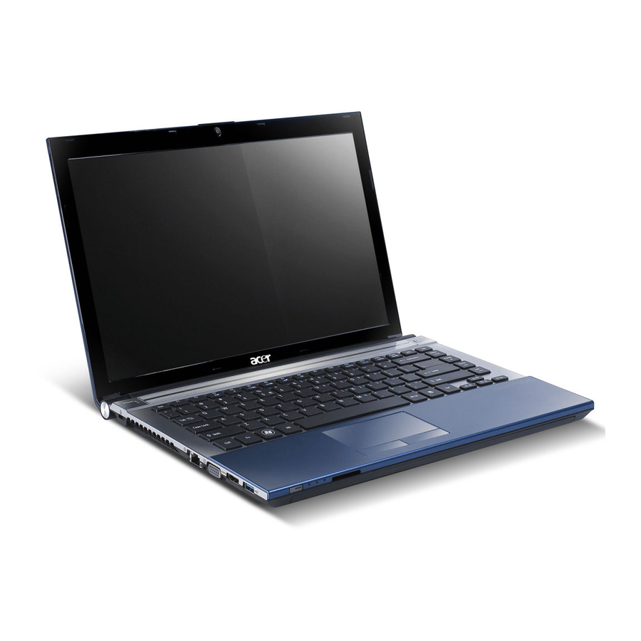
Page 14: Outlook Tour
Outlook Tour Front View Item Description "Launch keys" on page 10 Icon Item Icon Item Icon Icon Built-in camera Display screen Status indicators Wireless communication button Bluetooth communication button Microphone Touchpad Click buttons (left, center and right) Palmrest Chapter 1 "Launch keys"... -
Page 15: Closed Front View
Keyboard Power button Item Description Easy-launch buttons Closed Front View "Launch keys" on page 10 Icon Item Icon Item Icon Icon Item Speakers Line-in jack Icon Item Icon Item Microphone-in jack Icon Item Icon Item Headphones/speaker/ line-out jack with S/PDIF support Power indicator Battery indicator... -
Page 16: Left View
Left View Icon Item Icon Kensington lock slot Icon Item Optical disk drive Item Description Optical disk access indicator Note: Optical disk drive eject button Emergency eject hole "Easy-launch buttons" on page 10 Right View Icon Item Icon PC Card slot eject button Icon Item Icon... -
Page 17: Rear View
Rear View Icon Item Icon Item Icon Item Icon Icon Item USB 2.0 ports Icon Item S-video/TV-out(NTSC/ PAL)port Icon Item External display (VGA) port Connects to an external display device (e.g., external monitor, Modem (RJ-11) port Ethernet (RJ-45) port Battery Base View Icon Item... - Page 18 PCI Express Mini Card bay Houses the computer’s PCI Express Mini card. Hard disk bay Battery lock Battery bay Chapter 1 Houses the computer’s hard disk (secured with screws). Locks the battery in position. Houses the computer’s battery pack.
-
Page 19: Using The Keyboard
Using the Keyboard The full-sized keyboard includes an embedded numeric keypad, separate cursor, lock, Windows, function and special keys. Lock keys and Embedded Numeric Keypad The keyboard has three lock keys which you can toggle on and off. Lock key Lock Caps Lock When Caps Lock is on, all alphabetic characters are typed in uppercase. -
Page 20: Windows Keys
Displays help on hot keys. Acer eSetting Launches the Acer eSettings in Acer page 20 Empowering Technology. page 20 page 20 Acer ePower Launches the Acer ePower Management in Acer page 20 Management Empowering Technology. Sleep Leads the computer to Sleep mode. Description Description <... -
Page 21: Special Keys
<Fn> + <F4> <Fn> + <F5> <Fn> + <F5> Hot Key Icon <Fn> + <F5> <Fn> + <F6> <Fn> + <F5> <Fn> + <F6> Fn + F5 <Fn> + <F5> <Fn> + <F6> <Fn> + <F6> <Fn> + <F6> <Fn> + <F7> <Fn>... - Page 22 Either directly press the $ key on the bottom-right side of the keyboard, or hold Shift and then press the US dollar sign on the number four key. NOTE: This function varies according to the language settings. Chapter 1...
-
Page 23: Indicators
Indicators The computer provides an array of three indicators located above the keyboard, in addition to four Item indicators on the front cover. These indicators show the status of the computer and its components. Item Item Item Description "Launch keys" on page 10 The front panel indicators are visible even when the computer cover is closed up. -
Page 24: Easy-Launch Buttons
Easy-launch Buttons There are several conveniently located easy-launch buttons. They are one user-programmable button, web browser button, mail button, and Acer Empowering Key Empowering Technology. Although the mail and web browser buttons are pre-set to E-mail and Internet programs, they can be redefined by users. To set the web browser, mail and programmable buttons, run the Acer Launch Manager. -
Page 25: Touchpad
Touchpad The built-in touchpad is a pointing device that senses movement on its surface. This means the cursor responds as you move your finger across the surface of the touchpad. The central location on the palmrest provides optimum comfort and support. Touchpad Basics Use the touchpad as follows: Move your finger across the touchpad (2) to move the cursor. - Page 26 the touchpad’s responsiveness. NOTE: By default, vertical and horizontal scrolling is enabled on your touchpad. It can be disabled under Mouse settings in Windows Control Panel. Chapter 1...
-
Page 27: Acer Empowering Technology
Acer Empowering Technology Acer’s innovative Empowering Technology makes it easy to have access to the frequently used functions and manage the notebook. It features the following handy utilities: Acer eDataSecurity Management protects data with passwords and advanced encryption algorithms. Acer eLock Management limits access to external storage media. -
Page 28: Acer Edatasecurity Management
Acer eDataSecurity Management Acer eDataSecurity Management is a handy file encryption utility that protects the files from being accessed by unauthorized persons. It is conveniently integrated with Windows Explorer as a shell extension for quick and easy data encryption and decryption and also supports on-the-fly file encryption for MSN Messenger and Microsoft Outlook. - Page 29 Chapter 1...
-
Page 30: Acer Elock Management
The lock(s) will be set without any reboot necessary, and will remain locked after rebooting, until unlocked. If you do not set a password, Acer eLock Management will reset back to the initial status with all locks cancelled. -
Page 31: Acer Eperformance Management
Acer ePerformance Management Acer ePerformance Management is a system optimization tool that boosts the performance of the Acer notebook. It provides you with the following options to enhance overall system performance: Memory optimization: releases unused memory and checks memory usage. -
Page 32: Acer Erecovery Management
Recovery from CD or DVD • NOTE: If the computer did not come with a Recovery CD or System CD, please use Acer eRecovery Management’s “System backup to optical disk” feature to burn a backup image to CD or DVD. To ensure the best results when recovering the system using a CD or Acer eRecovery Management, detach all peripherals (except external Acer ODD, if equipped), including the Acer ezDock. -
Page 33: Acer Esettings Management
Acer eSettings Management Acer eSettings Management allows you to inspect hardware specification and to monitor the system health status. Furthermore, Acer eSettings Management enables you to optimize your Windows operating system, so your computer runs faster, smoother and better. Provides a simple graphical user interface for navigating through the program effortlessly. -
Page 34: Acer Enet Management
Acer eNet Management helps you to quickly and easily connect to both wired and wireless networks in a variety of locations. To access this utility, either click on the “Acer eNet Management” icon on the notebook, or start the program from the Start menu. You also have the option to set Acer eNet Management to start automatically when you boot up the PC. - Page 35 Chapter 1...
-
Page 36: Acer Epower Management
Acer ePower Management Acer ePower Management features a straightforward user interface. To launch it, select Acer ePower Management from the Empowering Technology interface, or double click the Acer ePower Management icon in the task tray. AC mode The default setting is “Maximum Performance.” You can adjust CPU speed, LCD brightness and other settings, or click on buttons to turn the following functions on or off: Wireless LAN, Bluetooth, CardBus, Memory Card, Audio, and Wired LAN. - Page 37 View information about Acer ePower Management. • Chapter 1...
-
Page 38: Acer Epresentation Management
Acer ePresentation Management Acer ePresentation Management lets you select from two of the most common projector resolution: XGA and SVGA. Chapter 1... -
Page 39: Acer Orbicam
The camera’s 225-degree ergonomic rotation allows you to capture high-resolution photos or videos up front or at the back of the LCD panel. The Acer OrbiCam fully supports the Acer Video Conference technology so that you can transmit the best video quality over an instant messenger service. - Page 40 Launching the Acer OrbiCam To launch the Acer OrbiCam, double click on the Acer OrbiCam icon on the screen. or Click Start > All programs > Acer > Acer OrbiCam. The Acer OrbiCam capture windows window appears as below: Changing the Acer OrbiCam settings...
-
Page 41: Camera Settings
Capturing photos or videos To capture a photo or a video clip, rotate the Acer OrbiCam to get the desired angle, then click the Take a Picture or Record a Video button. The Windows Picture and Fax Viewer or the Windows Media Player automatically launches to display or play a preview of the photo/video clip. - Page 42 Enabling the Acer VisageON The Acer VisageON technology comes with two features: Face tracking and Video effects (selected models only). The Face Tracking feature tracks your head movement and automatically centers your face in the capture window. The video effects feature allows you to select and apply an effect to your video transmissions.
- Page 43 Click the right icon to zoom in/out or reset the current view. VisageON Click VisageON to display a menu that allows to change the configuration of the camera, face tracking and video effects settings. VisageON VisageON Using video effects Video Settings Using video effects Using video effects (selected models only) Video Settings...
- Page 44 Click on a video effect to use. The selected effect appears in the video effects section of the VisageON window. NOTE: When using avatars, you may have to calibrate the face points to achieve better tracking. Follow screen instructions in the VisageON to continue. NOTE: You may use video effects when using the camera for IM chat/video sessions or call conferences.
-
Page 45: Using The System Utilities
Start All Programs multiple windows on the same screen. To access this function, please go to Start > All Programs and click on Acer GridVista. You may choose any one of the four display settings indicated below: Start All Programs Acer Gridvista is dual-display compatible, allowing two displays to be partitioned independently. -
Page 46: Launch Manager
NOTE: Please ensure that the resolution setting of the second monitor is set to the manufacturer's Note: recommended value. Note: Launch Manager "Easy-launch buttons" on page 24 Launch Manager allows you to set the four easy-launch buttons located above the keyboard. You can access the Launch Manager by clicking on Start >... -
Page 47: Norton Antivirus
Norton AntiVirus Norton AntiVirus is an anti-virus software that finds and repairs infected files, and protects against viruses to keep you computer data safe and secure. How do I check for viruses? A Full System Scan scans all files on your computer. To perform a system scan: Start Norton Antivirus: Double click on the Norton AntiVirus Icon on the desktop or click on the Start Start menu in the Windows task bar, highlight Programs, and select Norton Antivirus. -
Page 48: Hardware Specification And Configuration
Hardware Specification and Configuration Processor Item CPU type (1.6/1.8/2GHz, 2 x 512 KB L2 cache), TL-50 (1.6GHz, 2 x 256 KB L2 cache) AMD Sempron GHz, 512 KB L2 cache), 3400+ (1.8 GHz, 256 KB L2 cache) Package Socket S1, 638-pin lidless Micro-PGA Core voltage 1.2875V (highest frequency mode) to 0.8375V (low frequency mode) Feature... - Page 49 Hard Disk Drive Spindle Speed (RPM) Internal transfer rate (Mbytes/sec. max.) I/O data transfer rate (Mbytes/sec. max.) ATA data transfer mode supported Bytes per sector Average latency (msec) Average seek, read (msec. typical) Average seek, write (msec. typical) Cache buffer Interface Startup current (typical, peak) Ambient temperature...
- Page 50 BIOS Item Feature • Suspend to RAM (S3) / Disk (S4) • Support boot option: HDD / Removable device (media bay device) / • Support SMBIOS 2.3, PCI2.2, WFM2.0 • ACPI 2.0/3.0 compliance with Intel Speedstep Support C1, C2, C3, •...
- Page 51 • CISPR22 application Connector type RJ-11 Keyboard Item Controller ENE KB3910 Model name New Acer Ergo Keyboard Description ADCs with 85dB SNR (A-Weighting) Description Description latch, the wire of antenna can not be placed under the panel) Description Description Chapter 1...
- Page 52 • Standard pitch, 2.5 mm travel length • Hotkey controls • Embedded numeric keypad • Multi-language support • Spill-proof • Four easy-launch buttons: Internet browser, E-mail with LED, Acer Battery Item Vendor & model name Panasonic / Sanyo / Sony...
- Page 53 Item Surface treatment non-glare type (1) glare type (H) Pixel RGB vertical arrangement stripe Pixel pitch (mm) 0.255 (per one triad) x 0.255 Typical white 200 (typical) luminance (cd/ ) also called brightness Contrast ratio 350 (typical) Respond time 25 (typical) (optical rise time 35 (max.) + fall time)
- Page 54 Item Output ripple and noise Turn on delay time Temperature 24X Combo Drive Interface Item Vendor & model name Performance Specification Transfer rate (KB/sec.) Access Time (Typical) Buffer Memory Interface Applicable disc format Loading mechanism Power Requirement Input Voltage 8X DVD Dual Interface Item Vendor and model name Performance specification...
- Page 55 Item Transfer rate (KB/sec.) Access time (typical) Buffer memory Interface Applicable disc format Loading mechanism Power consumption Input voltage 8X Super Multi Interface Item Vendor and model name Performance Specification Transfer rate read (KB/ sec.) Access time / Seek time Buffer memory Interface Specification...
- Page 56 Item Applicable disc format Loading mechanism Power requirement Input voltage Chapter 1 Specification CD-DA, CD-ROM KODAK Photo CD Mode-1, CD-ROM/XA single and multi- Mode-2 Form-1 and session, CD Extra (CD Mode-2 Form-2, CD-I, PLUS), Video CD, CD Video-CD (MPEG-1), text data (read/write), CD-Text, PhotoCD, CD-R (read/write), Enhance CD, CD...
-
Page 57: Chapter2 System Utilities
System Utilities BIOS Setup Utility The BIOS Setup Utility is a hardware configuration program built into your computer’s BIOS (Basic Input/ Output System). Your computer is already properly configured and optimized, and you do not need to run this utility. However, if you encounter configuration problems, you may need to run Setup. -
Page 58: Information
WD-WXE406360816 System BIOS Version: v1.00 VGA BIOS Version: 5.51.28.45.00 08.10 KBC Version: Serial Number: 914Q901051G6310008C2000 Asset Tag Number: None Product Name: Aspire 9300 Manufacturer Name: Acer UUID: 2fb91de0-1d5f-11d7-8837-8a090087febe Help Select Item ↑ ↓ Exit Select Menu ← → Parameter CPU Type... -
Page 59: Main
Main This menu provides you the information of the system. Info. Main System Time: [11:59:38 ] System Date: [01/16/2006] System Memory: 640 KB Extended Memory: 254 KB Video Memory 128 MB Quiet Boot: [Enabled] Power on Display: [Auto ] [Enabled] Network boot [Disabled] F12 Boot Menu:... - Page 60 Parameter F12 Boot Menu When this is selected, users can modify device boot priority by pressing F12 key during POST. When this is not selected, device boot priority will not be adjustable during POST. D2D Recovery Allow user to enable/disable the Disk-to-Disk recovery Description Chapter 2...
-
Page 61: Security
Security The Security screen contains parameters that help safeguard and protect your computer from unauthorized use. Info. Main Supervisor Password Is: User Password Is: HDD Password Set Supervisor Password Set User Passord Set HDD Password Password on Boot: Help Select Item ↑... -
Page 62: Set Supervisor/User Password
Parameter Set HDD Password Password on boot Set Supervisor/User Password If password on boot is required, the password must be set otherwise it cannot be enabled. The formats of the password are as follows: Length No more than 8 characters Characters 0-9,A-Z (not case sensitive) While these fields are highlighted and press “Enter”, a window similar to the following is shown:... - Page 63 User can now type password in field “Enter New Password”, and re-enter password in field “Confirm New Password” for verification. If the verification is OK: The password setting is complete after user presses enter. Setup Notice Changes have been saved. [ continue] If the current password entered does not match the actual current password: Setup Warning...
-
Page 64: Boot
Boot This menu allows the user to decide the order of boot devices to load the operating system. Bootable devices includes the distette drive in module bay, the onboard hard disk drive and the CD-ROM in module bay and onboard LAN device. Info. -
Page 65: Exit
Exit Info. Main Exit Saving Changes Exit Dicarding Changes Load Setup Defaults Discard Changes Save Changes Help Select Item ↑ ↓ Exit Select Menu ← → The table below describes the parameters in this screen. Parameter Exit Saving Changes Exit System Setup and save your changes to CMOS Exit Discarding Exit utility without saving Setup data to CMOS Changes... -
Page 66: General Information
Machine Disassembly and Replacement General Information This chapter contains step-by-step procedures on how to disassemble the notebook for maintenance and troubleshooting. To disassemble the computer, you need the tools below: Wrist ground strap and conductive mat for preventing electrostatic discharge Small Philips screw driver Flat head screw driver Hexagonal driver... -
Page 67: Disassembly Procedure Flowchart
Disassembly Procedure Flowchart The flowchart gives you a graphic representation on the entire disassembly and reassembly and instructs you how to remove the components. Screws List Description SCW HEX NYL I#R-40/O#4-40 L5.5 SCREW MACH WAFER M2*L4 NI SCRW M2.5*6 ~ L-CASE + U-CASE SCRW M2*L3 SCRW M2.5*5 WAFER B-ZN ROHS SCREW M2*L3 NYLOK CR 3+... - Page 68 Screws List Description SCREW M2*L3 NON-NYLOK CR3+ SCREW M2.5*L6 NYLOK CR3+ SCREW M2.5*L8 NYLOK CR3+ SCREW M2*L8 NI NON-NYLOK SCREW M3x4(86.9A524.4R0) SCRW M2*4 WAFER NI SCREW NI M2*6L SCRW M2.5*L3(NON NYLOK) Chapter 3 Part No. 86.00E31.723 86.00E33.736 86.00E34.738 86.00E35.228 86.9A524.4R0 86.9A552.4R0 86.9A552.6R0 86.9A523.3R0...
-
Page 69: Disassembly Procedure
Disassembly Procedure Removing the Battery Pack Unlock the battery pack. Slide the battery latch, hold it then remove the battery. Removing the HDD Module Release the three screws fastening the HDD module cover. Detach the HDD module cover. Release the two screws holding the HDD module then pull the HDD module as arrow indicates and remove the HDD module. -
Page 70: Removing The Wireless Lan Card And The Ram Modules
Removing the Wireless LAN Card and the RAM Modules Release the two screws securing the wireless LAN card cover. Remove that cover. Disconnect the wireless antennae. The black is the main cable and the white is the auxiliary one. Press the left and the right latches to pop up the wireless LAN card. Chapter 3... - Page 71 Release the two screws securing the RAM cover and remove the RAM cover. Press the left and right latches to pop up the RAM module. Repeat the anterior step to remove other RAM module. Chapter 3...
-
Page 72: Removing The Keyboard
Removing the Keyboard Open the notebook as shown. Remove the middle cover. Though it is combined tightly, detach it from the main unit carefully. Do not pull it abruptly. There are four latches securing the keyboard. Push those latches by the screw driver as shown and the keyboard will pop up a little. Remove the keyboard and reverse it. -
Page 73: Separating The Lcd Module And Main Unit
Separating the LCD Module and Main Unit Pull carefully and disconnect the LCD cable. Tear off the tape securing the wireless antennae and pull out the wireless antennae. Release the two screws securing the LCD hinges on the bottom side. Release the two screws fastening the LCD hinges on the rear side. -
Page 74: Disassembling The Main Unit
Disassembling the Main Unit Separating the Upper Case and the Lower Case Release the connector lock and disconnect the touch pad FFC. Release the connector lock and disconnect the function keyboard FFC. Release the three screws securing the upper case. Release the 27 screws holding the lower case. -
Page 75: Removing The Function Keyboard
Removing the Function Keyboard Release the FFC lock and disconnect the function keyboard FFC. Release the four screws holding the function keyboard bracket. Then remove the function keyboard bracket. Carefully disconnect the microphone cable and remove the function keyboard. Chapter 3... - Page 76 Removing the Touch Pad Board Carefully release the FFC lock and disconnect the touch pad board FFC. There are 13 latches holding the touch pad bracket. Unlock those latches with a screw driver as shown then detach the touch pad bracket. Detach the touch pad board.
- Page 77 Removing the ODD Module and Dummy Card Slightly pull the ODD module and remove it. Pull the dummy card from the slot and remove it. Removing the Main Board Disconnect the fan cable. Disconnect the speaker cable and Bluetooth module cable. Remove the four screws securing the main board.
- Page 78 Removing the System Fan Release the two screws holding the heatsink. Remove the heatsink. Removing the Bluetooth Module Detach the bluetooth module from the lower case. Carefully disconnect the bluetooth module cable. Chapter 3...
- Page 79 Removing the Speakers Release the four screws securing the left and right speakers. Remove the speakers from the lower case. Removing the MDC Module Carefully disconnect the MDC cable. Release the two screws securing the MDC board then detach the MDC board. Disconnect the MDC board cable.
- Page 80 Remove the Heatsink Module Release the five screws securing the heatsink. Remove the heatsink module. Removing the CPU Release the screw counter clockwise with a flat screw driver. Detach the CPU from the CPU socket. Chapter 3...
-
Page 81: Lcd Disassembly
LCD Disassembly Remove the eight rubber caps on the LCD bezel and release the eight screws securing the LCD bezel. Detach the LCD bezel from the LCD module as shown. Release the screw holding the inverter board. Disconnect the inverter board cables as shown and remove the inverter board. Chapter 3... - Page 82 Release the four screws securing the LCD panel. Detach the LCD panel carefully and reverse it as shown. Tear off the tapes holding the LCD panel cable carefully then disconnect the LCD panel. Remove the antenna from the LCD cover. Chapter 3...
- Page 83 Release the four screws securing the left LCD bracket then remove the left LCD bracket. Repeat the anterior step to remove the right LCD bracket. Chapter 3...
- Page 84 Release the screw holding the CCD module and carefully pull the CCD module cable and LCD cable through the latch bar and LCD cover. Remove the CCD module cap. Remove the CCD module ring. Push the CCD module upper case a little bit. Then Separate the lower case from the upper case.
- Page 85 Chapter 3...
-
Page 86: Chapter4 Troubleshooting
Troubleshooting Please use the following procedures as a guide for computer problems. NOTE: The diagnostic tests are intended to test only Acer products. Non-Acer products, prototype cards, or modified options may occur errors or invalid responses. Obtain the detailed fail symptoms as many as possible. -
Page 87: System Check Procedures
System Check Procedures External Diskette Drive Check Do the following procedures to isolate the possible effects from a controller, driver, or diskette. A writable, diagnostic diskette is required. NOTE: Make sure that the diskette does not have more than one label attached. Multiple labels may cause damage to the drive or make the drive fail. -
Page 88: Memory Check
Numeric keypad External keyboard If any of these devices do not function, reconnect the cable and repeat the anterior procedures. Memory Check Follow the procedures below to correct the memory errors. Boot from the diagnostic diskette and start the diagnostic programs. Go to the diagnostic memory in the test items. -
Page 89: Check The Battery Pack
Check the Battery Pack Follow the procedures below to check the battery pack. From software, this helps to identify the problem is on recharging or discharging. Check the Power Management in Control Panel. Then confirm that the parameters shown in the screen for Current Power Source and Total Battery Power Remaining are correct. - Page 90 If the PS/2 mouse does not work, then click if the main board to switch board FPC is connected properly. If the main board to switch board FPC is connected correctly, then check if the FFC on the touch pad PCB is connected properly. If the FFC on the touch pad PCB is connected correctly, check if LS851 JP1 Pin6 = 5V are pules.
-
Page 91: Power-On Self-Test (Post) Error Message
Power-On Self-Test (POST) Error Message The POST error message index lists the error message and their possible causes. NOTE: Perform the FRU replacement or actions in the sequence shown in Error Message List, if the FRU replacement does not solve the problem, put the original part back in the computer. Do not replace a non-defective FRU. -
Page 92: Index Of Error Messages
Index of Error Messages Error Message List Error Messages Struck Key System CMOS checksum bad - Default configuration used Real time clock error Previous boot incomplete - Default configuration used Invalid System Configuration Data Operating system not found Power-on indicator turns off and LCD is blank. -
Page 93: Phoenix Bios Beep Codes
Phoenix BIOS Beep Codes Code Beeps 1-2-2-3 1-3-1-1 1-3-1-3 1-3-4-1 1-3-4-3 POST Routine Description Verify Real Mode Disable Non-Maskable Interrupt (NMI) Get CPU type Initialize system hardware Disable shadow and execute code from the ROM. Initialize chipset with initial POST values Set IN POST flag Initialize CPU registers... - Page 94 Code Beeps 2-1-2-3 2-2-3-1 Chapter 4 POST Routine Description Autosize cache Advanced configuration of chipset registers Load alternate registers with CMOS values Initialize extended memory for RomPilot. Initialize interrupt vectors POST device initialization Check ROM copyright notice Initialize I20 support Check video configuration against CMOS Initialize PCI bus and devices...
- Page 95 Code Beeps POST Routine Description Set up hardware interrupt vectors Initialize coprocessor if present Disable onboard Super I/O ports and IRQs Late POST device initialization Detect and install external RS232 ports Configure non-MCD IDE controllers Detect and install external parallel ports Initialize PC-compatible PnP ISA devices Re-initialize onboard I/O ports...
- Page 96 Code Beeps The following are for boot block in Flash ROM Chapter 4 POST Routine Description Inform RomPilot about the end of POST. POST done- prepare to boot operating system One short beep before boot Terminate QuietBoot (optional) Check password (optional) Initialize ACPI BIOS Prepare Boot Initialize SMBIOS...
- Page 97 Code Beeps POST Routine Description Initialize Multi Processor Initialize OEM special code Initialize PIC and DMA Initialize Memory type Initialize Memory size Shadow Boot Block System memory test Initialize interrupt vectors Initialize Run Time Clock Initialize video Initialize System Management Mode Output one beep Clear Huge Segment Boot to Mini DOS...
-
Page 98: Index Of Symptom-To-Fru Error Message
Index of Symptom-to-FRU Error Message LCD-Related Symptoms Symptom/Error LCD backlight doesn't work. LCD is too dark. LCD brightness cannot be adjusted. LCD contrast cannot be adjusted. Unreadable LCD screen Missing pels in characters Abnormal screen Wrong color displayed LCD has extra horizontal or vertical lines displayed. - Page 99 Power-Related Symptoms Symptom/Error The system doesn’t power-off. Battery can’t be charged. PCMCIA-Related Symptoms Symptom/Error System cannot detect the PC Card (PCMCIA). PCMCIA slot pin is damaged. Memory-Related Symptoms Symptom / Error Memory count (size) appears different from actual size. Speaker-Related Symptoms Symptom/Error In Windows, multimedia programs, no sound...
- Page 100 Power Management-Related Symptoms Symptom/Error The system does not enter standby mode after closing the LCD. The system does not resume from hibernation mode. The system does not resume from standby mode after opening the LCD. Battery fuel gauge in Windows does not go higher than 90%.
- Page 101 Keyboard/Touchpad-Related Symptoms Symptom/Error Touchpad does not work. Modem-Related Symptoms Symptom/Error Internal modem does not work correctly. NOTE: If you can not correct the problems according to the anterior tables, see “Undetermined Problems”. Action in Sequence Reconnect touchpad cable. Touchpad board System board Action in Sequence Modem phone port...
-
Page 102: Intermittent Problems
Intermittent Problems Intermittent system hang problems can be caused by a variety of reasons that have nothing to do with a hardware defect, such as cosmic radiation, electrostatic discharge, or software errors. FRU replacement should be considered only when a recurring problem exists. When analyzing an intermittent problems, follow the procedures below: Run the advanced diagnostic test for the system board in loop mode at least 10 times. -
Page 103: Undetermined Problems
Follow the procedures below to isolate the failing FRU. Do not isolate non-defective FRU. Power off the computer. Visually check the devices. If any problems are found, replace the FRU. Remove or disconnect all of the following devices: Non-Acer devices Printer, mouse, and other external devices Battery Pack Hard disk drive... -
Page 104: Top View
Jumper and Connector Location Top View Description DC-in jack CRT connector MDC module cable connector Main battery connector Mini PCI slot Chapter 5 Description USB connector RJ11 & RJ45 connector MDC board connector ODD connector North bridge DIMM slot Chapter 5... - Page 105 South bridge Line-in jack Line-out jack USB connector RTC battery connector Description Description HDD connector Microphone-in jack Cardbus controller BIOS ROM 5-in-1 card reader Chapter 5...
-
Page 106: Bottom View
Bottom View Item Keyboard controller Lid switch connector PCMCIA card reader Touch pad board connector Bluetooth module connector Chapter 5 Description Item Description Keyboard connector System fan connector Function key board connector Speaker connector LCD cable connector... -
Page 107: Switch Setting
Switch Setting SRN10KJ-5-GP SB GPIO PSW_CLR# MATRIXID1# MATRIXID2# Short G3 to clear password. 3D3V_S0 RN13 EC20 SC1000P50V3JN-GP GAP-OPEN SW-DIP-4-2-U2-GP 62.40013.061 Chapter 5... -
Page 108: Password Bypassing & Bios Recovery
Password Bypassing & BIOS Recovery For RD and CSD to debug easilly, AS7000/AS9300 provides one hardware PIN pad for bypassing Password Check, and one Hotkey to enable BIOS Recovery. PIN pad: To short PIN pad to bypass password check. Hotkey to enabe BIOS Recovery: Fn+ESC, then Power Button, AC+DC coexistence is strongly recommended. - Page 109 Choice what kind of the password to be generated: 0) Exit 1) Scan code 2) Upper case ASCII Code 3) Lower case ASCII Code Enter your choice 2 <- chose 2 XXXXXX XXXXXX XXXXXX Those passwords are master password. Restore BIOS by the Crisis Disk Enter this function by Fn+ESC, and Power Button.
-
Page 110: Chapter6 Fru (Field Replaceable Unit) List
NOT be noted on the printed service guide. For Acer authorized service providers, your Acer office may have a different part number code from those given in the FRU list of this printed service guide. You MUST use the local FRU list provided by your regional Acer office to order FRU parts for service. -
Page 111: Exploded Diagram
Exploded Diagram Chapter 6... -
Page 112: Parts
Parts Aspire 9300 G72M FRU List Category Part Name ADAPTER ADAPTER ADAPTER 90W LISHIN SLS0202C19A20LF ADAPTER ADAPTER 90W DELTA ADP- 90SB BBDAF ADAPTER ADAPTER 90W LITEON PA- 1900-24AR ADAPTER ADAPTER 90W DELTA ADP- 90SB BBAAF ADAPTER ADAPTER 90W LITEON PA-... - Page 113 ISRAEL CORD USA/W CNS 2.5A 27.01518.781 125V 8121- CODE UK 3A 250V 3P BK 27.01518.541 CODE 5A 250V 3P UK BK 27.03118.001 POWER CODE ACA / ACNZ 27.03218.021 ANNIE CORD CHINA 10A 250V 3P 27.01518.591 Acer Part No. Chapter 6...
- Page 114 42.AEFV1.002 ASSY MINIPCI COVER 42.AEFV1.003 MYALL ASSY DIMM COVER MYALL 42.AEFV1.004 KNOB T/P FRAME AS MYALL 42.ADFV1.003 ASSY L-CASE S-VIDEO 60.AEFV1.001 MYALL M SPEAKER MYALL 23.TCBV1.001 ASSY U-CASE S-VIDEO 60.AEFV1.002 MYALL M COVER SWITCH HT MYALL 50.TCBV1.004 Acer Part No.
- Page 115 KC.S3502.25F 25W F ASSY 24X COMBO PHILIPS 6M.AEFV1.002 MYALL M?? ODD BRKT MYALL 33.TCBV1.002 ASSY S_MULTI ODD BEZEL 42.TCBV1.013 GBASE SUP-MULT PHI/SDVD-8821 KU.00809.005 KERKINI S-MULTI LTN/SSM-8515S KU.00804.037 MYALL/2 S-MULT 8X TST/TS-L632D W/ KU.00801.014 O BZL Acer Part No. Chapter 6...
- Page 116 ASSY HDD CHASSIS MYALL 33.TCBV1.003 "HDD 80G 2.5"" 5400RPM KH.08007.013 HGST" KH.08004.006 5400RPM HDD 80GB SEAGATE KH.08001.022 ST98823A HDD 80GB WD WD800UE- KH.08008.029 22KVTO ASSY HGST 100G 5400RPM PATA ASSY HDD CHASSIS MYALL 33.TCBV1.003 HDD 100GB HGST 13G1591 KH.10007.004 ROHS Acer Part No.
- Page 117 KB DARFON NSK-AFA23 KB.ACF07.004 THAIL 105K KB DARFON NSK-AFA3B KB.ACF07.005 BRALI 106K KB DARFON NSK-AFA2K KB.ACF07.006 KOREA 105K KB DARFON NSK-AFA2U UK KB.ACF07.007 106K KB DARFON NSK-AFA2G KB.ACF07.008 GERMA 106K KB DARFON NSK-AFA2E KB.ACF07.009 ITALI 106K Acer Part No. Chapter 6...
- Page 118 KB.ACF07.027 SOLVE 106K MYALL M MB 06211-1 G72 MB.AF201.001 CONN CARDBUS 4P 59330- 22.T28V1.001 00L0C BTY RTC MITSUBISHI ROHS 23.TCBV1.003 MDC CABLE HT MYALL 50.TCBV1.006 MODEM MDC1.5 54.ABAV1.001 T60M845.02 ROHS ASSY 17.1 WXGA AUO+G 6M.AEFV1.011 MYALL M Acer Part No.
- Page 119 KIRKINI CAS CAMERA L-CASE 60.AEFV1.006 KIRKINI HLDR CAMERA SIDE RIM 42.AEFV1.006 KIRKINI HLDR CAMERA CAP KIRKINI 42.AEFV1.007 "ASSY LCD 17.1"" PANEL 60.AEFV1.005 CCD AS" LCD HINGE PACK LEFT/ 6K.ADFV1.001 RIGHT ASSY LCD BEZEL MYALL2 60.AEFV1.004 Acer Part No. Chapter 6...
- Page 120 BN2QA350K8SD79 BRKT-R LCD MYALL-2 33.ADFV1.001 BRKT-L LCD MYALL-2 33.ADFV1.002 LATCH CAMERA HINGH 33.AEFV1.001 KIRKINI CAS CAMERA L-CASE 60.AEFV1.006 KIRKINI HLDR CAMERA SIDE RIM 42.AEFV1.006 KIRKINI HLDR CAMERA CAP KIRKINI 42.AEFV1.007 "ASSY LCD 17.1"" PANEL 60.AEFV1.005 CCD AS" Acer Part No.
- Page 121 NANYA SODIMM 1G KN.1GB03.009 NT1GT64U8HA0BN-3C SODIMM 1G M470T2953CZ3- KN.1GB0B.005 SODIMM 256M KN.2560G.012 HYMP532S64BP6-C4 DIMM 256M KN.25603.029 NT256T64UH4A1FN-37B SODIMM256MHYS64T32000 KN.25602.023 HDL-3.7-A SODIMM 256M KN.25604.030 MT4HTF3264HY-53EB4 SODIMM 256M KN.2560B.017 M470T3354CZ3-CD5 SODIMM256MHYS64T32000 KN.25602.034 HDL-3.7-B SODIMM 256M KN.2560G.013 HYMP532S64BP6-Y5 Acer Part No. Chapter 6...
- Page 122 MICROPHONE FORGRAND 23.TCBV1.002 MYALL RUB LCD RUBBER 47.A46V1.002 CUSHION BOLSENA RUBBER SCREW MYALL 47.TCBV1.001 PLT LOGO PANEL 31.T49V1.001 "PLT BEZEL PLATE ""ACER "" 31.A46V1.001 LOGO" SCW HEX NYL I#R-40/O#4- 34.00015.081 40 L5.5 SCREW MACH WAFER 86.T39V1.002 M2*L4 NI SCREW M2*L3 (WHITE) 86.00C07.220...
- Page 123 SCREW Description SCRW M2.5X6 NON NYLOK 86.00F01.736 SCRW M2.5X5 NYLOK 86.00F19.735 SCRW M2X4 NYLOK H0.3 86.00F24.724 SCRW M2.5*L3(NON NYLOK) 86.9A523.3R0 SCRW M2*4 WAFER NI 86.9A552.4R0 SCREW NI M2*6L 86.9A552.6R0 SCREW MACH WAFER 86.9A524.4R0 M3*L4 NI Acer Part No. Chapter 6...
- Page 124 Chapter 6...
-
Page 125: Model Definition And Configuration
Model Definition and Configuration Model Description AS7003WSMi AS7003WSMi XPHSA1 UMAC 1*512/100/ 6L/5R/CB_bg_0.3C_AN AS7003WSMi AS7003WSMi XPHDK1 UMAC 1*512/100/ 6L/5R/CB_bg_0.3C_AN AS7003WSMi AS7003WSMi XPHBE1 UMAC 1*512/100/ 6L/5R/CB_bg_0.3C_AN AS7003WSMi AS7003WSMi XPHNL1 UMAC 1*512/100/ 6L/5R/CB_bg_0.3C_AN AS7003WSMi AS7003WSMi XPHNO1 UMAC 1*512/100/ 6L/5R/CB_bg_0.3C_AN AS7003WSMi AS7003WSMi XPHRU2 UMAC 1*512/100/ 6L/5R/CB_bg_0.3C_AN AS7003WSMi AS7003WSMi XPHSV1 UMAC 1*512/100/... - Page 126 Model AS7003WSMi AS7003WSMi XPHSA1 UMAC 2*512/120/ 6L/5R/CB_bg_0.3C_AN AS7003WSMi AS7003WSMi XPHDK1 UMAC 2*512/120/ 6L/5R/CB_bg_0.3C_AN AS7003WSMi AS7003WSMi XPHBE1 UMAC 2*512/120/ 6L/5R/CB_bg_0.3C_AN AS7003WSMi AS7003WSMi XPHFRA UMAC 2*512/120/ 6L/5R/CB_bg_0.3C_AN AS7003WSMi AS7003WSMi XPHDE7 UMAC 2*512/120/ 6L/5R/CB_bg_0.3C_AN AS7003WSMi AS7003WSMi XPHNL1 UMAC 2*512/120/ 6L/5R/CB_bg_0.3C_AN AS7003WSMi AS7003WSMi XPHNO1 UMAC 2*512/120/ 6L/5R/CB_bg_0.3C_AN AS7003WSMi AS7003WSMi XPHRU2 UMAC 2*512/120/...
- Page 127 Model AS7003WSMi AS7003WSMi XPHAU1 UMAC 1*512/100/ 6L/5R/CB_bg_0.3C_AN AS7003WSMi AS7003WSMi XPHFRA UMAC 2*512/100/ 6L/5R/CB_bg_0.3C_AN AS7003WSMi AS7003WSMi MCEBE6 UMAC 2*512/120/ 6L/5R/CB_bg_0.3C_AN AS7003WSMi AS7003WSMi MCECS5 UMAC 2*512/120/ 6L/5R/CB_bg_0.3C_AN AS7003WSMi AS7003WSMi MCEAR1 UMAC 2*512/120/ 6L/5R/CB_bg_0.3C_AN AS7003WSMi AS7003WSMi MCEAR2 UMAC 2*512/120/ 6L/5R/CB_bg_0.3C_AN AS7003WSMi AS7003WSMi MCEDEA UMAC 2*512/120/ 6L/5R/CB_bg_0.3C_AN AS7003WSMi AS7003WSMi MCEDEB UMAC 2*512/120/...
- Page 128 Model AS9302WSMi AS9302WSMi MCEBE6 NB7PSE128C 2*512/100/8L/5R/CB_bg_0.3C_AN AS9302WSMi AS9302WSMi MCENL6 NB7PSE128C 2*512/100/8L/5R/CB_bg_0.3C_AN AS9302WSMi AS9302WSMi MCENO5 NB7PSE128C 2*512/100/8L/5R/CB_bg_0.3C_AN AS9302WSMi AS9302WSMi MCEDK6 NB7PSE128C 2*512/100/8L/5R/CB_bg_0.3C_AN AS9302WSMi AS9302WSMi MCEFRF NB7PSE128C 2*512/100/8L/5R/CB_bg_0.3C_AN AS9302WSMi AS9302WSMi MCEDEA NB7PSE128C 2*512/100/8L/5R/CB_bg_0.3C_AN AS9302WSMi AS9302WSMi MCEDEB NB7PSE128C 2*512/100/8L/5R/CB_bg_0.3C_AN AS9302WSMi AS9302WSMi MCEESJ NB7PSE128C 2*512/100/8L/5R/CB_bg_0.3C_AN AS9302WSMi AS9302WSMi MCEIT7 NB7PSE128C...
- Page 129 Model AS9303WSMi AS9303WSMi MCENL6 NB7PSE128C 2*512/120/8L/5R/CB_bg_0.3C_AN AS9303WSMi AS9303WSMi MCENO5 NB7PSE128C 2*512/120/8L/5R/CB_bg_0.3C_AN AS9303WSMi AS9303WSMi MCECS5 NB7PSE128C 2*512/120/8L/5R/CB_bg_0.3C_AN AS9303WSMi AS9303WSMi MCEUK5 NB7PSE128C 2*512/120/8L/5R/CB_bg_0.3C_AN AS9303WSMi AS9303WSMi MCERU9 NB7PSE128C 2*512/120/8L/5R/CB_bg_0.3C_AN AS9303WSMi AS9303WSMi MCESV5 NB7PSE128C 2*512/120/8L/5R/CB_bg_0.3C_AN AS9303WSMi AS9303WSMi MCETR5 NB7PSE128C 2*512/120/8L/5R/CB_bg_0.3C_AN AS9303WSMi AS9303WSMi MCESW8 NB7PSE128C 2*512/120/8L/5R/CB_bg_0.3C_AN AS9303WSMi AS9303WSMi MCEPL7 NB7PSE128C...
- Page 130 Model AS9303WSMi AS9303WSMi MCEWIT11W NB7PSE128C 2*512/120/8L/5R/ CB_bg_0.3C_AN Model AS9302WSMi AS9302WSMi XPHSA1 UMAC 1*512/100/ 6L/5R/CB_bg_0.3C_AN AS9302WSMi AS9302WSMi XPHDK1 UMAC 1*512/100/ 6L/5R/CB_bg_0.3C_AN AS9302WSMi AS9302WSMi XPHBE1 UMAC 1*512/100/ 6L/5R/CB_bg_0.3C_AN AS9302WSMi AS9302WSMi XPHNL1 UMAC 1*512/100/ 6L/5R/CB_bg_0.3C_AN AS9302WSMi AS9302WSMi XPHNO1 UMAC 1*512/100/ 6L/5R/CB_bg_0.3C_AN AS9302WSMi AS9302WSMi XPHRU2 UMAC 1*512/100/ 6L/5R/CB_bg_0.3C_AN AS9302WSMi AS9302WSMi XPHSV1 UMAC 1*512/100/...
- Page 131 Model AS9302WSMi AS9302WSMi XPHWUK21W UMAC 1*512/100/6L/5R/CB_bg_0.3C_AN AS9302WSMi AS9302WSMi XPHSA1 UMAC 2*512/120/ 6L/5R/CB_bg_0.3C_AN AS9302WSMi AS9302WSMi XPHDK1 UMAC 2*512/120/ 6L/5R/CB_bg_0.3C_AN AS9302WSMi AS9302WSMi XPHBE1 UMAC 2*512/120/ 6L/5R/CB_bg_0.3C_AN AS9302WSMi AS9302WSMi XPHNL1 UMAC 2*512/120/ 6L/5R/CB_bg_0.3C_AN AS9302WSMi AS9302WSMi XPHNO1 UMAC 2*512/120/ 6L/5R/CB_bg_0.3C_AN AS9302WSMi AS9302WSMi XPHRU2 UMAC 2*512/120/ 6L/5R/CB_bg_0.3C_AN AS9302WSMi AS9302WSMi XPHSV1 UMAC 2*512/120/...
- Page 132 Model AS9302WSMi AS9302WSMi XPHFR1 UMAC 1*512/100/ 6L/5R/CB_bg_0.3C_AN AS9302WSMi AS9302WSMi XPHES1 UMAC 1*512/100/ 6L/5R/CB_bg_0.3C_AN AS9302WSMi AS9302WSMi XPHXC1 UMAC 1*512/100/ 6L/5R/CB_bg_0.3C_AN AS9302WSMi AS9302WSMi MCEAU1 UMAC 1*512/100/ 6L/5R/CB_bg_0.3C_AN AS9302WSMi AS9302WSMi MCESG1 UMAC 1*512/ 100/6L/5R/CB_bg_0.3C_AN AS9302WSMi AS9302WSMi XPHFRA UMAC 2*512/120/ 6L/5R/CB_bg_0.3C_AN AS9301AWSMi AS9301AWSMi MCEBE6 UMAC 2*512/ 100/6L/5R/CB_bg_0.3C_AN AS9301AWSMi AS9301AWSMi MCENL6 UMAC 2*512/...
- Page 133 Model AS9302WSMi AS9302WSMi MCEUS UMAC 2*512/120/ 6L/5R/CB_bg_0.3C_AN AS9302WSMi AS9302WSMi MCEES1 UMAC 2*512/120/ 6L/5R/CB_bg_0.3C_AN AS9302WSMi AS9302WSMi MCECF UMAC 2*512/160/ 6L/5R/CB_bg_0.3C_AN AS9302WSMi AS9302WSMi MCEES1 UMAC 2*512/160/ 6L/5R/CB_bg_0.3C_AN AS9302WSMi AS9302WSMi MCEUS UMAC 2*512/160/ 6L/5R/CB_bg_0.3C_AN AS9301AWSMi AS9301AWSMi MCEAR1 UMAC 2*512/ 100/6L/5R/CB_bg_0.3C_AN AS9301AWSMi AS9301AWSMi MCEAR2 UMAC 2*512/ 100/6L/5R/CB_bg_0.3C_AN AS9301AWSMi AS9301AWSMi MCEWUK11W UMAC...
- Page 134 Model AS9302WSMi AS9302WSMi MCERU9 UMAC 2*512/ 120/6L/5R/CB_bg_0.3C_AN AS9302WSMi AS9302WSMi MCETR5 UMAC 2*512/120/ 6L/5R/CB_bg_0.3C_AN AS9302WSMi AS9302WSMi MCESW8 UMAC 2*512/ 120/6L/5R/CB_bg_0.3C_AN AS9302WSMi AS9302WSMi MCESV5 UMAC 2*512/120/ 6L/5R/CB_bg_0.3C_AN AS9302WSMi AS9302WSMi MCEUK5 UMAC 2*512/120/ 6L/5R/CB_bg_0.3C_AN AS9302WSMi AS9302WSMi MCEWUK11W UMAC 2*512/120/6L/5R/CB_bg_0.3C_AN AS9302WSMi AS9302WSMi MCEWIT11W UMAC 2*512/ 120/6L/5R/CB_bg_0.3C_AN AS9302WSMi AS9302WSMi MCEWDE11W UMAC...
- Page 135 Appendix A...
-
Page 136: Test Compatible Components
Appendix B Test Compatible Components This computer’s compatibility is tested and verified by Acer’s internal testing department. All of its system ® ® functions are tested under Windows XP Home, Windows XP Pro environment. Refer to the following lists for components, adapter cards, and peripherals which have passed these tests. -
Page 137: Microsoft Windows
Token Ring 16/4 Adapter II Advance PC Card List - 3G/GPRS Card Sony Ericsson GC89 GPRS Card Vodafone 3G/GPRS Card I/O Peripheral List - External CRT Acer "211c 21""" ViewSonic G220F ViewSonic "PF790 19""" I/O Peripheral List - External LCD ®... - Page 138 Vendor Acer "FP751 17"" TFT LCD" Acer "15"" LCD Monitor (DVI) Model:AL1521(*1)" P Acer "17"" LCD Monitor (DVI) Model:AL1721(*1)" P ViewSonic "20'' LCD VD201b(DVI-I) ,(DVI-D),(D-sub) (*1)" I/O Peripheral List - Projector MultiSync MT-1040 I/O Peripheral List - Scanner Acer AcerScan Prisa 620P...
- Page 139 Vendor Apacer USB Handy Drive 32/128/256/512MB Apacer USB2.0 Handy Driver 256/512MB Sony Memery Key 128MB I/O Peripheral List - USB Hub and Others A TEN 4 Port Hub (usb 2.0) IOGEAR 4 Port Hub (usb 2.0) Corega WirelessLAN USB Stick11 (usb 1.1) *1 I/O Peripheral List - USB Peripheral Logitec CDRW + DVDROM combo USB interface...
- Page 140 Vendor I/O Peripheral List - Misc Peripheral X Bridge Bluetooth Access Point BT300 I/O Peripheral List - Bluetooth Device(*1) Sony Ericsson Wireless Headset Deskjet 995C (bluetooth interface) X Bridge Bluetooth Access Point BT300 EPSON Bluetooth Print Adapter Microsoft HID Bluetooth Keyboard & Mouse Sony Ericsson T610 I/O Peripheral List - Multimedia Card(*1)
- Page 141 Appendix B...
-
Page 142: Online Support Information
This section describes online technical support services available to help you repair your Acer Systems. If you are a distributor, dealer, ASP or TPM, please refer your technical queries to your local Acer branch office. Acer Branch Offices and Regional Business Units may access our website. However some information sources will require a user i.d. - Page 143 Appendix C...