
Related Manuals for Acer Aspire 5020


Summary of Contents for Acer Aspire 5020
- Page 1 Aspire 3020/5020 Series Service Guide Service guide files and updates are available on the ACER/CSD web; for more information, please refer to http://csd.acer.com.tw PRINTED IN TAIWAN...
-
Page 2: Revision History
Revision History Please refer to the table below for the updates made on Aspire 3020/5020 service guide. Date Chapter Updates... - Page 3 Copyright Copyright © 2005 by Acer Incorporated. All rights reserved. No part of this publication may be reproduced, transmitted, transcribed, stored in a retrieval system, or translated into any language or computer language, in any form or by any means, electronic, mechanical, magnetic, optical, chemical, manual or otherwise, without the prior written permission of Acer Incorporated.
- Page 4 Conventions The following conventions are used in this manual: SCREEN MESSAGES NOTE WARNING CAUTION IMPORTANT Denotes actual messages that appear on screen. Gives bits and pieces of additional information related to the current topic. Alerts you to any damage that might result from doing or not doing specific actions.
- Page 5 DIFFERENT part number code to those given in the FRU list of this printed Service Guide. You MUST use the list provided by your regional Acer office to order FRU parts for repair and service of customer machines.
-
Page 7: System Specifications
Below is a brief summary of the computer’s many feature: Platform and memroy Aspire 3020 Series Mobile AMD Sempron Mobile AMD Sempron Aspire 5020 Series AMD Turion 64 ML-28/ML-32 processor at 1.6/1.8 GHz or higher with 128 KB L1 cache and 512 KB L2 cache, or AMD Turion 64 ML-30/ML-34/ML-37/ML-40 processor at 1.6/1.8/2.0/2.2 GHz or higher with 128... - Page 8 Modem (RJ-11) port Extternal display (VGA) port S-video/TV-out port Microphone/line-in jack Headphones/speaker/line-out port Infrared (FIR) port Type II PC Card slot 6-in-1 card reader DC-in jack for AC adaptor WLAN solution (for selected models); Acer SignalUp wireless ® Chapter 1...
-
Page 9: System Block Diagram
System Block Diagram See 'TEXT' in 0MEMO or 1MEMO property in component Bolsena Block Diagram Dummy when 'USE EZ4' Dummy when 'NO EZ4' Dummy when use '10/100' Dummy when use 'GIGA' CLK GEN IDT CV137 Dummy when use 'UMA' Dummy when use 'DIS' LEDs Dummy when use 'SATA' RTC BAT. -
Page 10: Board Layout
Board Layout Top View Keyboard Connector Bluetooth Board Connector LCD Cable Connector LED Board Connector Lid Switch Modem Cable Connector 3 in 1 Connector Speaker Connector Internal Microphone Connector Modem Board Connector Touchpad Board Connector Chapter 1... -
Page 11: Table Of Contents
Bottom View Power Jack Docking Audio Cable Connector Main Battery Connector ODD Connector Media Bay Connector Mini PCI Slot Second Battery Connector RTC Battery Connector DDR DIMM Connector HDD Connector Chapter 1 Audio Cable Connector Line-in Connector Headphone Out Connector Microphone-in Connector USB Connector IEEE 1394 Connector... - Page 12 Bluetooth Switch Wireless Switch LAN Cable Connector FAN Connector LAN Cable Connector Chapter 1...
-
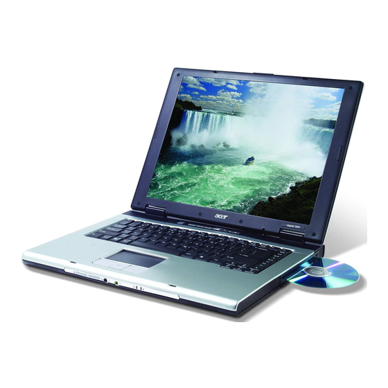
Page 13: An Aspire Tour
An Aspire tour After knowing your computer features, let us show you around your new TravelMate computer. Front View Item Icon Chapter 1 Description Item Display screen Also called LCD (liquid-crystal display), displays computer output. Power button Turns the computer on and off. Microphone Internal microphone for sound recording. -
Page 14: Closed Front View
Closed Front View Icon Item Icon Speakers Bluetooth communication button/ indicator Wireless communication button/ indicator Line-in/mic-in jack Speaker/Line-Out/ Headphone jack Battery indicator Power indicator Latch Description Item Description Left and right speakers deliver stereo audio output. ® Press to enable/disable Bluetooth function. Lights to indicate the status of Bluetooth- communications (manufacturing option). -
Page 15: Left View
Left View Icon Icon Right View Item Icon Chapter 1 Item Description Item Ventilation slots Enable the computer to stay cool, even after prolonged use. S-video/TV-out port Connects to a television or display device with S-video input (manufacturing option). IEEE 1394 port Connects to IEEE 1394 devices (manufacturing option). -
Page 16: Power Jack
Note: Rear Panel Icon Item Icon Optical drive eject Ejects the optical drive tray from the drive. button Optical disk access LED that indicates when an optical disk is indicator being read or written. Optical drive Internal optical drive; accepts CDs or DVDs depending on the optical drive type. -
Page 17: Bottom Panel
Bottom Panel Item Item Wireless LAN bay Battery lock Battery release latch Battery bay Cooling fan Memory and hard disk Indicators The computer has four easy-to-read status indicators on the upper-right above the keyboard, and four on the front panel. The power, battery and wireless communication status indicators are visible even when the LCD display is closed. -
Page 18: Launch Keys
Web browser, Acer Empowering key “ Press “ “ to ru the Acer eManager. Please see “Acer eManager”. The mail and Web buttons are pre-set to email and Internet programs, but can be reset by users. To set the Web browser, mail and programmable keys, run the Acer Launch Manager. -
Page 19: Touchpad Basics
The central location on the palmrest provides optimum comfort and support. Touchpad Basics The following teaches you how to use the touchpad: Chapter 1 Default application Email application (user-programmable) Internet browser (user-programmable) Acer eManager (user-programmable) User-programmable... - Page 20 Move your finger across the touchpad (2) to move the cursor. Press the left (1) and right (4) buttons located beneath the touchpad to perform selection and execution functions. These two buttons are similar to the left and right buttons on a mouse. Tapping on the touchpad is the same as clicking the left button.
-
Page 21: Using The Keyboard
Using the Keyboard The keyboard has full-sized keys and an embedded keypad, separate cursor keys, two Windows keys and twelve function keys. Lock Keys and embedded mumeric keypad The keyboard has three lock keys which you can toggle on and off. Lock Key Caps Lock When Caps Lock is on, all alphabetic characters typed... -
Page 22: Hot Keys
This key has the same effect as clicking the right mouse button; it opens the application’s context menu. Function Hot key help Displays help on hot keys. Acer eSetting Launches the Acer eSettings in Acer eManager. Acer Launches the Acer ePowerManagement in Acer ePowerManagement eManager. Description Chapter 1... -
Page 23: Special Key
Hot Key Icon Fn-F4 Fn-F5 Fn-F6 Fn-F7 Fn-F8 Fn-w Fn-y Fn-x Fn-z Special Key You can locate the Euro symbol and US dollar sign at the upper-center and/or bottom-right of your keyboard. To type: Chapter 1 Function Sleep Puts the computer in Sleep mode. Display toggle Switches display output between the display screen, external monitor (if connected) and both. - Page 24 The Euro symbol Open a text editor or word processor. Either directly press the <Euro> symbol at the bottom-right of the keyboard, or hold <Alt Gr> and then press the<5> symbol at the upper-center of the keyboard. The US dollar sign Open a text editor or word processor.
-
Page 25: Hardware Specifications And Configurations
1.0a, DMI 2.0, PS/2 keyboard and mouse, USB 2.0, VGA BIOS, CD-ROM bootable, IEEE 1394 Set by setup manual Specification Built-in CPU 128KB/256KB for Aspire 3020 Series 512KB/1MB for Aspire 5020 Series Always enabled Always enabled Fixed in write-back Specification AMD CPU built-in... -
Page 26: Memory Combinations
System Memory Item Supports DIMM voltage Supports DIMM package Memory module combinations Memory Combinations Slot 1 128MB 128MB 128MB 1284MB 256MB 256MB 256MB 256MB 512MB 512MB 512MB 512MB 1024MB 1024MB 1024MB 1024MB 1024MB NOTE: Above table lists some system memory configurations. You may combine DIMMs with various capacities to form other combinations. - Page 27 IR Interface Item Performance Compliant Modem Interface Item Data modem data baud rate (bps) Supports modem protocol Modem connector type Modem connector location Bluetooth Interface Item Chipset Data throughput Protocol Interface Connector type Wireless Module 802.11b/g (optional device) Item Chipset Data throughput Protocol Interface...
- Page 28 Hard Disk Drive Interface Item Capacity (MB) 40000 Bytes per sector Data heads Drive Format Disks Spindle speed 4200 RPM (RPM) Performance Specifications Buffer size 2048KB Interface ATA/ATAPI-6; ATA-6 Max. media transfer rate (disk-buffer, Mbytes/s) Data transfer 100 MB/Sec. rate Ultra DMA mode-5 (host~buffer, Mbytes/s)
- Page 29 DVD-Dual Interface Item Transfer rate (KB/sec) Buffer Memory Interface Applicable disc format Loading mechanism Power Requirement Input Voltage Audio Interface Item Audio Controller Audio onboard or optional Mono or Stereo Resolution Compatibility Mixed sound source Voice channel Sampling rate Internal microphone Internal speaker / Quantity Video Interface Item...
- Page 30 Video Memory Item Chipset Memory size Interface USB Port Item Chipset USB Compliancy Level OHCI Number of USB port Location Serial port function control IEEE 1394 Port Item Chipset Number of IEEE 1394 port Location Connector type PCMCIA Port Item PCMCIA controller Supports card type Number of slots...
- Page 31 System Board Major Chips Item Wireless 802.11 b+g PCMCIA Audio 6-in-1 card reader Keyboard Item Keyboard controller Total number of keypads Windows logo key Internal & external keyboard work simultaneously Battery Item Vendor & model name Battery Type Pack capacity Number of battery cell Package configuration Normal voltage...
- Page 32 LCD 15 inch Item Typical Power Consumption (watt) Weight Physical Size(mm) Electrical Interface Support Color Viewing Angle (degree) Horizontal: Right/Left Vertial: Upper/Lower ° Temperature Range( C) Operating Storage (shipping) LCD 15 inch and 15.4 inch Item Vendor & model name Screen Diagonal (mm) Active Area (mm) Display resolution (pixels)
- Page 33 LCD Inverter Item Vendor & model name Brightness conditions Input voltage (V) Input current (mA) Output voltage (V, rms) Output current (mA, rms) Output voltage frequency (k Hz) AC Adaptor Item Input rating Maximum input AC current Inrush current Efficiency System Power Management ACPI mode Mech.
- Page 34 Chapter 1...
-
Page 35: System Utilities
BK-ATI VER008.025M.000.000 VGA BIOS Ver 01.17 KBC Ver xxxxxxxxxxxxxxxxxxxxxx Serial Number Asset Tag Number Product Name TravelMate 4400 Manufacturer Name: Acer xxxxxxxxxxxxxxxxxxxxxxxxxxxxxxxx UUID: Help Select Item ↑ ↓ ← → Exit Select Menu Chapter 2 during POST (when “Press <F2> to enter Setup” message is prompted... -
Page 36: Navigating The Bios Utility
Navigating the BIOS Utility There are six menu options: Info., Main, System Devices, Security, Boot, and Exit. Follow these instructions: To choose a menu, use the cursor left/right keys (zx). To choose a parameter, use the cursor up/down keys ( wy). To change the value of a parameter, press por q. - Page 37 VGA BIOS Ver 01.17 KBC Ver xxxxxxxxxxxxxxxxxxxxxx Serial Number Asset Tag Number Product Name TravelMate 4400 Manufacturer Name: Acer xxxxxxxxxxxxxxxxxxxxxxxxxxxxxxxx UUID: Help Select Item ↑ ↓ ← → Exit Select Menu NOTE: The system information is subject to different models.
- Page 38 Main The Main screen displays a summary of your computer hardware information, and also includes basic setup parameters. It allows the user to specify standard IBM PC AT system parameters. Info. Main System Time: System Date: System Memory: 640 KB Extended Memory: 477 MB Video Memory...
- Page 39 The table below describes the parameters in this screen. Settings in boldface are the default and suggested parameter settings. Parameter System Time Sets the system time. The hours are displayed with 24-hour format. System Date Sets the system date. System Memory This field reports the memory size of the system.
- Page 40 Advanced The Advanced menu screen contains parameters involving your hardware devices. It also provides advanced settings of the system. Info. Main Infrared Port (FIR) Base I/O address: Interrupt: DMA channel: Serial port A: Parallel port: Legacy USB Support Help Select Item ↑...
- Page 41 Parameter Description Options Enabled Legacy USB Support Enables, disables USB interface devices support. Option: or Disabled (Enable for use with a non-USB aware Operating System such as DOS or UNIX). Chapter 2...
- Page 42 Security The Security screen contains parameters that help safeguard and protect your computer from unauthorized use. Info. Main User Password is : Supervisor Password is : Set Supervisor Password Set User Password Password on Boot Help Select Item ↑ ↓ ←...
- Page 43 The table below describes the parameters in this screen. Settings in boldface are the default and suggested parameter settings. Parameter User Password is Supervisor Password is Set User Password Set Supervisor Password Password on Boot NOTE: When you are prompted to enter a password, you have three tries before the system halts. Don’t forget your password.
- Page 44 Type the current password in the Enter Current Password field and press e. Press e twice without typing anything in the Enter New Password and Confirm New Password fields. The computer then sets the Supervisor Password parameter to “Clear”. When you have changed the settings, press u to save the changes and exit the BIOS Setup Utility. Changing a Password Use the w and y keys to highlight the Set Supervisor Password parameter and press the e key.
- Page 45 If the new password and confirm new password strings do not match, the screen will display the following message. Chapter 2...
- Page 46 Boot This menu allows the user to decide the order of boot devices to load the operating system. Bootable devices includes the distette drive in module bay, the onboard hard disk drive and the CD-ROM in module bay. Info. Main +Hard Drive Floppy Devices CD-ROM/DVD Drive...
-
Page 47: Exit
Exit The Exit screen contains parameters that help safeguard and protect your computer from unauthorized use. Info. Main Exit Saving Changes Exit Dicarding Changes Load Setup Defaults Discard Changes Save Changes Help ↑ ↓ Select Item ← → Exit Select Menu The table below describes the parameters in this screen. -
Page 48: Bios Flash Utility
BIOS Flash Utility The BIOS flash memory update is required for the following conditions: New versions of system programs New features or options Restore a BIOS when it becomes corrupted. Use the Phlash utility to update the system BIOS flash ROM. NOTE: If you do not have a crisis recovery diskette at hand, then you should create a Crisis Recovery Diskette before you use the Phlash utility. -
Page 49: Machine Disassembly And Replacement
Machine Disassembly and Replacement This chapter contains step-by-step procedures on how to disassemble the notebook computer for maintenance and troubleshooting. To disassemble the computer, you need the following tools: Wrist grounding strap and conductive mat for preventing electrostatic discharge Small Philips screw driver Philips screwdriver Plastic flat head screw driver Tweezers... -
Page 50: General Information
General Information Before You Begin Before proceeding with the disassembly procedure, make sure that you do the following: Turn off the power to the system and all peripherals. Unplug the AC adapter and all power and signal cables from the system. Remove the battery pack. -
Page 51: Disassembly Procedure Flowchart
Disassembly Procedure Flowchart The flowchart on the succeeding page gives you a graphic representation on the entire disassembly sequence and instructs you on the components that need to be removed during servicing. For example, if you want to remove the system board, you must first remove the keyboard, then disassemble the inside assembly frame in that order. - Page 52 LCD Panel Screw List Item Description SCW HEX NYL I#R-40/O#4-40 L5.5 SCREW MACH WAFER M2*L4 NI CPU SCREW M2.5*6.5 (2.7KG) CPU SCREW M2.5*6.5 (4.5KG) SCRW WH MS+CBZ M2.5+L4 BLACK SCREW M2.5-6 SCREW M2*3 NYLON 1JMCPC-420325 SCREW M2.5X6 SCREW M2-3 SCRW M2.5*L3(NON NYLOK) SCREW M2.5-5 SCREW M3x4(86.9A524.4R0) SCREW WAFER NYLOK NI 2ML3...
-
Page 53: Removing The Battery Pack
Removing the Battery Pack Unlock the battery lock. Slide the battery latch then remove the battery. Chapter 3... - Page 54 Removing the Memory/the HDD Module/the Wireless LAN Card/the ODD Module and the LCD Module Removing the Memory and the HDD Module Remove the three screws fastening the DIMM/HDD cover. Detach the DIMM/HDD cover carefully. Pop out the memory then remove it. Remove four screws fastening the HDD module.
-
Page 55: Removing The Odd Module
Removing the ODD Module Remove the screws fastening the ODD module as shown. Use a flat headed screwdriver to push the ODD module outwards then remove it. Removing the LCD Module Open the notebook as the impage shows. Detach the middle cover carefully as shown. Remove the screw holding the keyboard. - Page 56 Take out the LCD cable from the main unit then disconnect the cable. Remove two screws fastening the LCD module. Remove another two screws on the bottom as shown. 10. Then detach the entire LCD module cautiously. Chapter 3...
-
Page 57: Disassembling The Main Unit
Disassembling the Main Unit Separate the Main Unit Into the Upper and the Lower Case Assembly Disconnect the touchpad cable from the main board. Disconnect the microphone cable then remove the microphone. Remove one screw holding the upper case and the lower case assembly. Then remove 13 screws on the bottom as shown. -
Page 58: Disassembling The Lower Case Assembly
Detach the touchpad bracket carefully. Then detach the touchpad from the touchpad bracket. Disassembling the Lower Case Assembly Disconnect the bluetooth cable then remove the bluetooth module. Disconnect the speaker set cable from the main board. Remove two screws fastening the main board to the lower case. Remove three screws fastening the fan to the lower case. - Page 59 Disconnect the modem board cable from the main board. Remove the two screws holding the modem board. 10. Disconnect the modem board from the main board then remove it. 11. Disconnect the modem cable from the modem board. 12. Remove the three screws holding the CPU heatsink. 13.
- Page 60 18. Remove the three screws fastening the speaker set. 19. Tear off the tape holding the speaker set. 20. Take out the speaker set from the lower case. This completes main unit disassembly. Chapter 3...
-
Page 61: Disassembling The Lcd Module
Disassembling the LCD Module Remove the four screw caps as shown. Remove the four screws holding the LCD bezel. Then detach the LCD bezel from the LCD module. Remove the two screws fastening the LCD inverter. Take out the LCD inverter from the LCD cover, then disconnect the LCD cable from the inverter. Disconnect the inverter cable and remove the inverter. -
Page 62: Disassembling The External Modules
Disassembling the External Modules Disassembling the HDD Module Remove the two screws holding the HDD bracket on one side. Remove another two screws holding the HDD bracket on the other side. Then take the hard disc drive out from the HDD bracket. Chapter 3... -
Page 63: Troubleshooting
Troubleshooting Use the following procedure as a guide for computer problems. NOTE: The diagnostic tests are intended to test only Acer products. Non-Acer products, prototype cards, or modified options can give false errors and invalid system responses. Obtain the failing symptoms in as much detail as possible. -
Page 64: System Check Procedures
System Check Procedures External Diskette Drive Check Do the following to isolate the problem to a controller, driver, or diskette. A write-enabled, diagnostic diskette is required. NOTE: Make sure that the diskette does not have more than one label attached to it. Multiple labels can cause damage to the drive or cause the drive to fail. -
Page 65: Memory Check
If any of these devices do not work, reconnect the cable connector and repeat the failing operation. Memory check Memory errors might stop system operations, show error messages on the screen, or hang the system. Boot from the diagnostics diskette and start the doagmpstotics program (please refer to main board. Go to the diagnostic memory in the test items. - Page 66 Check the Power Adapter Unplug the power adapter cable from the computer and measure the output voltage at the plug of the power adapter cable. See the following figure If the voltage is not correct, replace the power adapter. If the voltage is within the range, do the following: Replace the System board.
-
Page 67: Touchpad Check
Check the Battery Pack To check the battery pack, do the following: From Software: Check out the Power Management in control Panel In Power Meter, confirm that if the parameters shown in the screen for Current Power Source and Total Battery Power Remaining are correct. -
Page 68: Power-On Self-Test (Post) Error Message
Power-On Self-Test (POST) Error Message The POST error message index lists the error message and their possible causes. The most likely cause is listed first. NOTE: Perform the FRU replacement or actions in the sequence shown in FRU/Action column, if the FRU replacement does not solve the problem, put the original part back in the computer. -
Page 69: Error Message List
Index of Error Messages Error Code List Error Codes <No error code> <No error code> Error Message List Error Messages Failure Fixed Disk Stuck Key Keyboard error Keyboard Controller Failed Keyboard locked - Unlock key switch Monitor type does not match CMOS - Run Setup Run “Load Default Settings” in BIOS Setup Utility. Shadow RAM Failed at offset: nnnn System RAM Failed at offset: nnnn Extended RAM Failed at offset: nnnn... - Page 70 Error Message List Error Messages Real time clock error Previous boot incomplete - Default configuration used Memory size found by POST differed from CMOS Diskette drive A error Incorrect Drive A type - run SETUP System cache error - Cache disabled CPU ID: DMA Test Failed Software NMI Failed...
- Page 71 Error Message List No beep Error Messages No beep, power-on indicator turns off and LCD is blank. No beep, power-on indicator turns on and LCD is blank. No beep, power-on indicator turns on and LCD is blank. But you can see POST on an external CRT.
-
Page 72: Phoenix Bios Beep Codes
Phoenix BIOS Beep Codes Code Beeps Verify Real Mode Disable Non-Maskable Interrupt (NMI) Get CPU type Initialize system hardware Initialize chipset with initial POST values Set IN POST flag Initialize CPU registers Enable CPU cache Initialize caches to initial POST values Initialize I/O component Initialize the local bus IDE Initialize Power Management... - Page 73 Code Chapter 4 Beeps 2-1-2-3 Check ROM copyright notice Check video configuration against CMOS Initialize PCI bus and devices Initialize all video adapters in system QuietBoot start (optional) Shadow video BIOS ROM Display BIOS copyright notice Display CPU type and speed Initialize EISA board Test keyboard Set key click if enabled...
-
Page 74: Docking
Code Beeps Initialize floppy controller Determine number of ATA drives (optional) Initialize hard-disk controllers Initialize local-bus hard-disk controllers Jump to UserPatch2 Build MPTABLE for multi-processor boards Install CD ROM for boot Clear huge ES segment register Fixup Multi Processor table Search for option ROMs. - Page 75 Code Code Chapter 4 Beeps Unknown interrupt Beeps Initialize the chipset Initialize the bridge Initialize the CPU Initialize the system timer Initialize system I/O Check force recovery boot Checksum BIOS ROM Go to BIOS Set Huge Segment Initialize Multi Processor Initialize OEM special code Initialize PIC and DMA Initialize Memory type...
-
Page 76: Index Of Symptom-To-Fru Error Message
Index of Symptom-to-FRU Error Message LCD-Related Symptoms Symptom / Error LCD backlight doesn't work LCD is too dark LCD brightness cannot be adjusted LCD contrast cannot be adjusted Unreadable LCD screen Missing pels in characters Abnormal screen Wrong color displayed LCD has extra horizontal or vertical lines displayed. - Page 77 Power-Related Symptoms Symptom / Error Battery can’t be charged PCMCIA-Related Symptoms Symptom / Error System cannot detect the PC Card (PCMCIA) PCMCIA slot pin is damaged. Memory-Related Symptoms Symptom / Error Memory count (size) appears different from actual size. Speaker-Related Symptoms Symptom / Error In Windows, multimedia programs, no sound comes from the computer.
- Page 78 Power Management-Related Symptoms Symptom / Error Battery fuel gauge in Windows doesn’t go higher than 90%. System hangs intermittently. Peripheral-Related Symptoms Symptom / Error System configuration does not match the installed devices. External display does not work correctly. USB does not work correctly Print problems.
-
Page 79: Intermittent Problems
Intermittent Problems Intermittent system hang problems can be caused by a variety of reasons that have nothing to do with a hardware defect, such as: cosmic radiation, electrostatic discharge, or software errors. FRU replacement should be considered only when a recurring problem exists. When analyzing an intermittent problem, do the following: Run the advanced diagnostic test for the system board in loop mode at least 10 times. -
Page 80: Undetermined Problems
System Check” on page 59.): Power-off the computer. Visually check them for damage. If any problems are found, replace the FRU. Remove or disconnect all of the following devices: Non-Acer devices Printer, mouse, and other external devices Battery pack Hard disk drive... -
Page 81: Odd Connector
Jumper and Connector Locations Top View Please note that the main board view file will not be provided by the vendor. Please use the utility to open main board file to see the top view and the bottom of this model. 13 (PJ1) Power Jack 15 (CN14) -
Page 82: Hdd Connector
19 (CN17) MINI PCI 21 (U21) CPU Socket 23 (CN19) USB Connector 25 (U23) EC PC97551 27 (CN20) DDR SO-DIMM Socket1 29 (CN21) DDR SO-DIMM Socket2 31 (CN22) PCMCIA Connector 33 (CN24) USB Connector 35 (CN25) Microphone Jack 37 (SW2) WLAN Button 39 (LED2) Battery LED... -
Page 83: Bottom View
Bottom View 1 (SW1) Lid Switch 3 (CN2) LED Board Connector 5 (CN4) Keyboard Connector 7 (CN6) Touchpad Board Connector 9 (U12) Clock Generator 11 (CN9) MDC Connector Chapter 5 2 (CN1) Panel Connector 4 (CN3) Modem Connector 6 (CN5) Bluetooth Module Connector 8 (CN7) Internal Microphone Connector... - Page 84 Chapter 5...
- Page 85 DIFFERENT part number code from those given in the FRU list of this printed Service Guide. You MUST use the local FRU list provided by your regional Acer office to order FRU parts for repair and service of customer machines.
- Page 86 Aspire 3020/5020 FRU List Adapter Battery Board Cable ADAPTER 90W LITEON PA-1900- 04AW BATTERY PACK LI+ 8CELL 2.2MAH SANYO BATTERY PACK LI+ 8CELL 2.2MAH PANASONIC WIRELESS LAN BOARD 802.11BG FOXCONN MODEM BOARD FOXCONN T60M845.01 Acer Incorporated AP.09003.002 BT.00803.007 BT.00805.002 54.A56V1.002 54.A56V1.001 Chapter 6...
- Page 87 Aspire 3020/5020 FRU List CASE/COVER/BRACKET ASSEMBLY Chapter 6 MODEM CABLE TOUCHPAD CABLE COVER SWITCH CABLE POWER CABLE 16A 250V 3PIN EUR POWER CORD 220V 3PIN EUR POWER CORD 10A 125V 3PIN US POWER CORD 10A 125V US POWER CORD 10A 250V 3PIN CHINA POWER CORD 3A 250V 3PIN UK POWER CORD 10A 250V 3PIN BK...
- Page 88 Aspire 3020/5020 FRU List CPU/Processor DVD-RW Module IO BRACKET LEFT LOWER CASE W/SPEAKER SPEAKER LEFT/RIGHT UPPER CASE W/COVER SWITCH CABLE AMD MOBILE SEMPRON 2600+ 25WD AMD MOBILE SEMPRON 2800+ 25WD AMD MOBILE SEMPRON 3000+ 25WD AMD MOBILE SEMPRON 3100+ 25WD DVD-RW MODULE 8X DUAL 33.A46V1.002 60.A46V1.001...
- Page 89 Aspire 3020/5020 FRU List Heatsink Chapter 6 OPTICAL BRACKET DVD-RW 8X DUAL LITEON SOSW- 833S W/BEZEL DVD-RW MODULE 8X DUAL OPTICAL BRACKET DVD-RW 8X TOSHIBA TS-L532A DUAL W/BEZEL CPU HEATSINK CPU HEATSINK CPU HEATSINK VGA HEATSINK HDD BRACKET 33.A46V1.003 KU.00804.015 6M.A46V1.004 33.A46V1.003 KU.00801.009...
- Page 90 Aspire 3020/5020 FRU List Keyboard HDD 40GB HITACHI HTS424040M9AT00 HDD 40GB TOSHIBA MK4025GAS HDD 40GB 4200PRM SEAGATE ST94019A HDD BRACKET HDD 60GB HITACHI C25N060ATMR04 HDD 60GB SEAGATE ST960821A HDD 60GB TOSHIBA MK6025GAS HDD BRACKET HDD 80G HITACHI IC25N080ATMR04 HDD 80G SEAGATE ST9808210A KEYBOARD DARFON NSK-H3M1D US INTERNATIONAL KEYBOARD DARFON NSK-H3M02...
- Page 91 Aspire 3020/5020 FRU List LCD Module Chapter 6 KEYBOARD DARFON NSK-H3M0D DANISH KEYBOARD DARFON NSK-H3M0T TURKISH KEYBOARD DARFON NSK-H3M0L GREEK KEYBOARD DARFON NSK-H3M0R RUSSIAN ASSY LCD MODULE 15IN. XGA W/ ANTENNA INVERTER BOARD DARFON V0.21189301 LCD/INVERTER CABLE 15" XGA LCD BRACKET 15" LEFT LCD BRACKET 15"...
- Page 92 LCD 15.4IN. WXGA LG LP154W01- A5K2 GLARE TYPE LCD 15.4IN. WXGA CHIMEI N154I1- L07 GLARE TYPE MAINBOARD M26P128MB/6IN1/GBL W/O CPU W/PCMCIA SLOT & RTC BATTERY (for Aspire 5020) MAINBOARD M24P64MBSAMSUNG/ 6IN1/GBL W/O CPU W/PCMCIA SLOT & RTC BATTERY (for Aspire 3020) RTC BATTERY PCMCIA SLOT/PC CARD SLOT 60.A46V1.007...
- Page 93 Aspire 3020/5020 FRU List Microphone Miscellaneous Pointing Device Screw Chapter 6 SDIMM 256M NANYA NT256D64SH8C0GM-6K SDIMM 256M INFINEON HYS64D32020HDL-6-C (.11U/G) SDIMM 256M HYNIX HYMD232M646D6-J SDIMM 256M SAMSUNG M470L3224FT0-CB3 SDIMM 256M MICRON MT8VDDT3264HG-335G3 SDIMM 512M HYNIX HYMD564M646B6-J SDIMM 512M INFINEON HYS64D64020HBDL-6-C SDIMM 512M SAMSUNG M470L6524CU0-CB3 MICROPHONE...
- Page 94 Aspire 3020/5020 FRU List SRW M2.5*8L B/ZN NYLOK 700 SCRW M2.5*L3(NON NYLOK) SCREW M3x4(86.9A524.4R0) SCREW WAFER NYLOK NI 2ML3 SCRW M2*4 WAFER NI SCRW M2.5*3 WAFER NI 86.9A353.8R0 86.9A523.3R0 86.9A524.4R0 86.9A552.3R0 86.9A552.4R0 86.9A553.3R0 Chapter 6...
- Page 95 Chapter 6...