
Related Manuals for Acer Aspire 4810TZ Series


Summary of Contents for Acer Aspire 4810TZ Series
- Page 1 Aspire 4810T/4810TZ/4410T/4810TG Series Service Guide Service guide files and updates are available on the ACER/CSD web; for more information, please refer to http://csd.acer.com.tw PRINTED IN TAIWAN...
-
Page 2: Revision History
Revision History Please refer to the table below for the updates made on Aspire 4810T/4810TZ/4410T/4810TG Series service guide. Date Chapter Updates... - Page 3 Copyright Copyright © 2009 by Acer Incorporated. All rights reserved. No part of this publication may be reproduced, transmitted, transcribed, stored in a retrieval system, or translated into any language or computer language, in any form or by any means, electronic, mechanical, magnetic, optical, chemical, manual or otherwise, without the prior written permission of Acer Incorporated.
- Page 4 Conventions The following conventions are used in this manual: SCREEN MESSAGES NOTE WARNING CAUTION IMPORTANT Denotes actual messages that appear on screen. Gives bits and pieces of additional information related to the current topic. Alerts you to any damage that might result from doing or not doing specific actions.
- Page 5 DIFFERENT part number code to those given in the FRU list of this printed Service Guide. You MUST use the list provided by your regional Acer office to order FRU parts for repair and service of customer machines.
-
Page 7: Table Of Contents
Using the System Utilities ..........17 Acer GridVista (dual-display compatible) ......17 Hardware Specifications and Configurations . - Page 8 Table of Contents Removing the Thermal Module ........63 Removing the Mini Board Module .
-
Page 9: System Specifications
Celeron mobile processor* • ® Mobile Intel GS45 Express Chipset • ™ Acer InviLink Nplify • System Memory Dual-Channel SDRAM support • Up to 2 GB of DDR3 1066 MHz memory, upgradeable to 4 GB using two soDIMM modules* •... - Page 10 Communication Integrated Acer Crystal Eye webcam • ® Wi-Fi/WiMAX: Intel Wireless WiFi Link 5150* • WWAN: • UMTS/HSPA at 900 MHz/2100 MHz and quad-band GSM/GPRS/EDGE • (850/900/1800/1900 MHz)* UMTS/HSPA at 850 MHz/900 MHz/1900 MHz/2100 MHz and quad-band GSM/GPRS/EDGE • (850/900/1800/1900 MHz)* WLAN: •...
-
Page 11: Aspire 4810T/4810Tz/4410T System Block Diagram
Aspire 4810T/4810TZ/4410T System Block Diagram Chapter 1... -
Page 12: Aspire 4810Tg System Block Diagram
Aspire 4810TG System Block Diagram Chapter 1... -
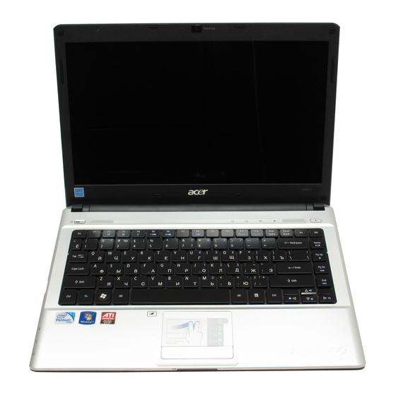
Page 13: Your Acer Notebook Tour
Comfortable support area for your hands when you use the computer. Turns the internal touchpad on and off. Enables / disables the WLAN / 3G functions. Launches Acer Backup Management for three-step data backup. Puts your computer into power-saving mode. Indicates when the hard disk drive is active. -
Page 14: Closed Front View
Closed Front View Icon Battery 5-in-1 card reader Item Indicates the computer's battery status. 1. Charging: The light shows amber when the battery is charging. 2. Fully charged: The light shows blue when in AC mode. Accepts Secure Digital (SD), MultiMediaCard (MMC), Memory Stick (MS), Memory Stick PRO (MS PRO), xD- Picture Card (xD). -
Page 15: Left View
Left View Icon HDMI Chapter 1 Item USB 2.0 port Connect to USB 2.0 devices (e.g., USB mouse, USB camera). Ventilation slots Enable the computer to stay cool, even after prolonged use. External display Connects to a display device (e.g., external monitor, LCD (VGA) port projector). -
Page 16: Right View
Right View Icon Item Optical drive Internal optical drive; accepts CDs or DVDs. Optical disk access Lights up when the optical drive is active. indicator Emergency eject hole Ejects the optical drive tray when the computer is turned off. Note: Insert a paper clip to the emergency eject hole to eject the optical drive tray when the computer is off. -
Page 17: Rear View
Rear View Icon Item Description Battery bay Houses the computer's battery pack. Chapter 1... -
Page 18: Bottom View
Bottom View Icon Battery bay Battery lock Memory compartment Hard disk bay Ventilation slots and cooling fan Battery release latch Item Houses the computer's battery pack. Locks the battery in position. Houses the computer's main memory. Houses the computer's hard disk (secured with screws). -
Page 19: Indicators
Indicates the computer's battery status. 1. Charging: The light shows amber when the battery is charging. 2. Fully charged: The light shows blue when in AC mode. Launches Acer Backup Management for three-step data backup. Puts your computer into power-saving mode. Description Description... - Page 20 Function Left button (2) Execute Quickly click twice. Select Click once. Drag Click and hold, then use finger on the touchpad to drag the cursor. Access context menu NOTE: Illustrations for reference only. The exact configuration of your PC depends on the model purchased. NOTE: When using the touchpad, keep it —...
-
Page 21: Using The Keyboard
Using the Keyboard The keyboard has full-sized keys and an embedded numeric keypad, separate cursor, lock, Windows, function and special keys. Lock Keys and Numeric Keypad The keyboard has three lock keys which you can toggle on and off. Lock key Caps Lock When Caps Lock is on, all alphabetic characters typed are in uppercase. -
Page 22: Windows Keys
Windows Keys The keyboard has two keys that perform Windows-specific functions. Windows Pressed alone, this key has the same effect as clicking on the Windows Start button; it launches the Start menu. It can also be used with other keys to provide a variety of functions: <... -
Page 23: Hot Keys
Hot Keys The computer employs hotkeys or key combinations to access most of the computer’s controls like screen brightness, volume output and the BIOS utility. To activate hot keys, press and hold the <Fn> key before pressing the other key in the hotkey combination. Hotkey Icon <Fn>... -
Page 24: Windows Mobility Center
Windows Mobility Center also includes Acer-specific settings like sharing folders overview/sharing service on or off, Bluetooth Add Device (if applicable), and a shortcut to the Acer user guide, drivers and utilities. To launch Windows Mobility Center: Use the shortcut key <... -
Page 25: Using The System Utilities
Apply to confirm the new settings and click OK to complete the process. Acer GridVista is a handy utility that offers four pre-defined display settings so you can view multiple windows on the same screen. To access this function, please go to Start>All Programs and click on Acer GridVista. - Page 26 NOTE: Please ensure that the resolution setting of the second monitor is set to the manufacturer's recommended value. Chapter 1...
-
Page 27: Hardware Specifications And Configurations
Hardware Specifications and Configurations Processor Item CPU type Core logic CPU package CPU core voltage CPU Fan True Value Table DTS(degree C) Fan Speed (rpm) 45-50 0-3000 55-66 0-3300 68-74 3300-3800 78-83 3800-4100 86-91 4100-4800 Throttling 50%: On= 99 C; OFF=93 C ... - Page 28 Memory Combinations Slot 1 1024MB 1024MB 1024MB 2048MB 2048MB 2048MB NOTE: Above table lists some system memory configurations. You may combine DIMMs with various capacities to form other combinations. On above table, the configuration of slot 1 and slot 2 could be reversed.
- Page 29 Hard Disk Drive Interface Item Vendor & HGST Model Name HTS543216L9A300 SEAGATE SATA ST9160310AS F/ TOSHIBA MK1655GSX WD WD1600BEVT- 22ZCT0 Capacity 160000 (MB) Bytes per sector Data heads Drive Format Disks Spindle 5400 RPM speed (RPM) Performance Specifications Buffer size Interface SATA Max.
- Page 30 Optical Disc Drive Item Applicable disc format Loading mechanism Power Requirement Input Voltage Audio Interface Item Audio Controller Audio onboard or optional Mono or Stereo Resolution Compatibility Sampling rate Internal microphone Internal speaker / Quantity Specification Applicable disc format CD: CD-DA, CD-ROM, CD-ROM XA, Photo CD (multi-session), Video CD, Cd-Extra (CD+), CD-text DVD: DVD-VIDEO, DVD-ROM, DVD-R (3.9GB, 4.7GB) DVD-R DL, DVD-RW, DVD-RAM, DVD+R, DVD+R DL, DVD+RW...
- Page 31 Video Memory Item Chipset Memory size Item Chipset USB Compliancy Level OHCI Number of USB port Location Serial port function control System Board Major Chips Item Core logic USB 2.0 Super I/O controller MODEM Bluetooth Wireless 802.11 b+g PCMCIA/ 5-in-1 Card Reader Audio Codec Keyboard Item...
- Page 32 LCD 14” inch Item Vendor & model name Screen Diagonal (mm) Display resolution (pixels) Pixel Pitch Pixel Arrangement Display Mode Typical White Luminance (NIT) also called Brightness Luminance Uniformity Contrast Ratio Response Time msec Nominal Input Voltage VDD Viewing Angle (degree) Horizontal: Right/Left Vertical: Upper/Lower ...
- Page 33 System Power Management ACPI mode Power Management Save to Disk (S4) Also called Hibernation Mode. System saves all system states and data onto the disc prior to power off the whole system. Chapter 1...
- Page 34 Chapter 1...
-
Page 35: System Utilities
System Utilities BIOS Setup Utility The BIOS Setup Utility is a hardware configuration program built into your computer’s BIOS (Basic Input/ Output System). Your computer is already properly configured and optimized, and you do not need to run this utility. However, if you encounter configuration problems, you may need to run Setup. -
Page 36: Navigating The Bios Utility
Navigating the BIOS Utility There are six menu options: Information, Main, Security, Boot, and Exit. Follow these instructions: To choose a menu, use the left and right arrow keys. • To choose an item, use the up and down arrow keys. •... -
Page 37: Information
Information The Information screen displays a summary of your computer hardware information. NOTE: The system information is subject to different models. Parameter CPU Type This field shows the CPU type and speed of the system. CPU Speed This field shows the speed of the CPU. IDE0 Model Name This field shows the model name of HDD installed on primary IDE master. -
Page 38: Main
Main The Main screen allows the user to set the system time and date as well as enable and disable boot option and recovery. I n f o r m a t i o n M a i n S y s t e m Ti m e : S y s t e m D a t e : S y s t e m M e m o r y : E x t e n d e d M e m o r y :... - Page 39 Parameter D2D Recovery Enables, disables D2D Recovery function. The function allows the user to create a hidden partition on hard disc drive to store operation system and restore the system to factory defaults. SATA Mode Control the mode in which the SATA controller should operate.
-
Page 40: Security
Security The Security screen contains parameters that help safeguard and protect your computer from unauthorized use. I n f o r m a t i o n M a i n S u p e r v i s o r P a s s w o r d I s U s e r P a s s w o r d I s H D D P a s s w o r d S e t S u p e r v i s o r P a s s w o r d... -
Page 41: Setting A Password
NOTE: When you are prompted to enter a password, you have three tries before the system halts. Don’t forget your password. If you forget your password, you may have to return your notebook computer to your dealer to reset it. Setting a Password Follow these steps as you set the user or the supervisor password: Use the up/down keys to highlight the Set Supervisor Password parameter and press the Enter key. -
Page 42: Changing A Password
Changing a Password Use the up/down keys to highlight the Set Supervisor Password parameter and press the Enter key. The Set Password box appears: Type the current password in the Enter Current Password field and press Enter. Type a password in the Enter New Password field. Retype the password in the Confirm New Password field. -
Page 43: Boot
Boot This menu allows the user to decide the order of boot devices to load the operating system. Bootable devices includes the diskette drive in module bay, the onboard hard disk drive and the CD-ROM in module bay. Chapter 2... -
Page 44: Exit
Exit The Exit screen contains parameters that confirmed or discard the changes made to the parameters in the BIOS Setup Utility. I n f o r m a t i o n M a i n E x i t S a v i n g C h a n g e s E x i t D i s c a r d i n g C h a n g e s D i s c a r d C h a n g e s S a v e C h a n g e s... -
Page 45: Bios Flash Utility
BIOS Flash Utility BIOS Flash Utility The BIOS flash memory update is required for the following conditions: New versions of system programs • New features or options • Restore a BIOS when it becomes corrupted. • Use the Flash utility to update the system BIOS flash ROM. NOTE: If you do not have a crisis recovery disk at hand, then you should create a Crisis Disk (See “Steps for BIOS Recovery by Crisis Disk”... -
Page 46: Remove Hdd And Bios Passwords
Remove HDD and BIOS Passwords This section teaches you how to remove HDD password: Remove HDD Password If you key in the wrong HDD password thrice, “HDD password error code” will appear on the • screen. See the image below. If you need to solve HDD password locked problem, you can run HDD_PW.EXE •... -
Page 47: Remove Bios Password
Remove BIOS Password If you key in wrong Supervisor Password for three time, “System Disabled” would display on the • screen. See the image below. If you need to solve BIOS password locked problem, you can run BIOS_PW.EXE • Key in “bios_pw 14452 0” Choose one upper-case string Reboot the system and key in “qjjg9vy”... - Page 48 Chapter 2...
-
Page 49: Machine Disassembly And Replacement
Machine Disassembly and Replacement This chapter contains step-by-step procedures on how to disassemble the notebook computer for maintenance and troubleshooting. Disassembly Requirements To disassemble the computer, you need the following tools: Wrist grounding strap and conductive mat for preventing electrostatic discharge •... -
Page 50: General Information
General Information Pre-disassembly Instructions Before proceeding with the disassembly procedure, make sure that you do the following: Turn off the power to the system and all peripherals. Unplug the AC adapter and all power and signal cables from the system. Place the system on a flat, stable surface. -
Page 51: External Module Disassembly Process
External Module Disassembly Process EXTERNAL MODULE DISASSEMBLY BATTERY MODULE OPTICAL DISK Item Screw M2 x L3 M3 x L3 M2.5 x L6 M2.5 x L11 Chapter 3 TURN OFF POWER AND PERIPHERALS UNPLUG POWER CABLES REMOVE BATTERY PACK Captive Screwx5 LOWER COVER DIMM... -
Page 52: Removing The Battery Pack
Removing the Battery Pack Turn base unit over. Slide the battery lock/unlock latch to the unlock position. Slide and hold the battery release latch to the release position. Then slide out the battery from the battery bay. Note: Battery has been highlighted with the yellow circle as above image shows. Please detach the battery and follow local regulations for disposal. -
Page 53: Removing The Lower Cover
Removing the Lower Cover See “Removing the Battery Pack” on page 44. Remove the two screws (F) and five captive screws securing the lower cover. Step Size (Quantity) M2.5 x L11 (2) Use a plastic screw driver to carefully pry open the lower cover. Remove the lower cover from the lower case. -
Page 54: Removing The Optical Drive Module
Removing the Optical Drive Module See “Removing the Battery Pack” on page 44. See “Removing the Lower Cover” on page 45. Remove the one screw (E) securing the optical drive. Step Size (Quantity) M2.5 x L6 (1) Remove the one screw (B) securing the locker bracket and remove the locker bracket from the optical disk drive module. -
Page 55: Removing The Hard Disk Drive Module
Push out the latches on both sides of the DIMM socket to release the DIMM and remove it from the socket. Do the same to the other socket if there is any DIMM present. Removing the Hard Disk Drive Module See “Removing the Battery Pack”... -
Page 56: Removing The Ssd Module
Remove the two screws (D) securing the hard disk to the bracket and remove the hard disk from the bracket. Step Size (Quantity) M3 x L3 (2) Removing the SSD Module See “Removing the Battery Pack” on page 44. See “Removing the Lower Cover” on page 45. Using the plastic tab, slide the SSD module away from the connector and lift to remove it from the system. - Page 57 Disconnect the RTC battery cable from the system board and lift to remove it. NOTE: Be careful when removing the RTC battery. It is glued to the system board. Note: RTC battery has been highlighted with the yellow circle as above image shows. Please detach the RTC battery and follow local regulations for disposal.
-
Page 58: Main Unit Disassembly Process
Main Unit Disassembly Process TOUCHPAD LCD MODULE LOCK BOARD SPEAKER MODULE A x 1 MINI BOARD Item Screw M2 x L4 M2.5 x L6 M2.5 x L5 M2 x L6 MAIN UNIT DISASSEMBLY MAIN UNIT KEYBOARD A x 1 WLAN BOARD MODULE H x 8 I x 2, Ex2... -
Page 59: Removing The Keyboard
Removing the Keyboard See “Removing the Battery Pack” on page 44. Release the keyboard from the latches securing it. Carefully pry loose the keyboard. Place the keyboard below the LCD screen to gain access to the keyboard cable. Chapter 3... -
Page 60: Removing The Wlan Board Module
Disconnect the keyboard cable from the main board to remove the keyboard. Removing the WLAN Board Module See “Removing the Battery Pack” on page 44. See “Removing the Keyboard” on page 51. Disconnect the antenna cables from the WLAN board. NOTE: There are 2 antenna cables connected to the WLAN board. -
Page 61: Separating The Upper Case From The Lower Case
Remove the one screw (A) on the WLAN board to release the WLAN board. Step Size (Quantity) M2 x L4 (1) Detach the WLAN board from the WLAN socket. NOTE: When attaching the antenna back to the WLAN board, make sure the cable are arranged properly. Separating the Upper Case from the Lower Case See “Removing the Battery Pack”... - Page 62 11. Remove the twelve screws (I, E, H) from the bottom panel. Step Size (Quantity) M2.5 x L6 (2) M2 x L4 (2) 5~12 M2.5 x L5 (8) 12. Disconnect the touchpad cable from the TPAD1 connector on the main board. 13.
-
Page 63: Removing The Power Button Board
14. Disconnect the power button cable from the BTB2 connector on the system board. 15. Disconnect the speaker cable from the SPK1 connector on the system board. 16. Gently separate the upper case from the lower case. Removing the Power Button Board See “Removing the Battery Pack”... -
Page 64: Removing The Touchpad Module
See “Removing the Optical Drive Module” on page 46. See “Removing the DIMM” on page 46. See “Removing the Hard Disk Drive Module” on page 47. See “Removing the SSD Module” on page 48. See “Removing the RTC Battery” on page 48. See “Removing the Keyboard”... -
Page 65: Removing The Speaker Module
12. Disconnect the touchpad cable from the touchpad board; then carefully pry loose and remove the touch pad board WARNING:The touchpad board is glued to the upper case, only remove the touchpad board if it is defective. Note: Circuit boards >10 cm² has been highlighted with the yellow rectangle as above image shows. Please detach the Circuit boards and follow local regulations for disposal. -
Page 66: Removing The Led Board
12. Remove the two screws (A) securing the left and right speaker modules, peel off the stickers securing the speaker cables, and remove them from the upper case. Step Size (Quantity) M2 x L4 (2) Removing the LED Board See “Removing the Battery Pack” on page 44. See “Removing the Lower Cover”... -
Page 67: Removing The Lcd Module
13. Carefully pry loose and remove the LED board from the upper case. WARNING:The LED board is glued to the upper case, only remove the LED board if it is defective. Removing the LCD Module See “Removing the Battery Pack” on page 44. See “Removing the Lower Cover”... - Page 68 13. Disconnect the LCD cable. 14. Pell off the LCD cable from the fan. 15. Remove the two screws (E) from the left and right hinge of the LCD module. Step Size (Quantity) Color Torque M2.5 x L6 (2) Black 3.0 kgf-cm Chapter 3...
-
Page 69: Removing The System Board
16. Carefully remove the LCD module from the base unit. NOTE: When connecting the cables back to the unit, please note that the cables should be routed well. Removing the System Board See “Removing the Battery Pack” on page 44. See “Removing the Lower Cover”... - Page 70 14. For the UMA model, disconnect the top CRT cable from the system board and the bottom CRT cable from the CRT board. 15. For the Discrete model, disconnect the CRT cable from CN2 on the system board and disconnect the CRT cable connector from CN3 on the system board.
-
Page 71: Removing The Thermal Module
16. Remove the one screw (A) securing the system board and the mini board.. Step Size (Quantity) M2 x L4 (1) 17. Carefully remove the main board. Removing the Thermal Module There are two version of thermal module. For this section, we are going to use the UMA model (for Aspire 4810T/4810TZ/4410T). - Page 72 See “Removing the Battery Pack” on page 44. See “Removing the Lower Cover” on page 45. See “Removing the Lower Cover” on page 45. See “Removing the Optical Drive Module” on page 46. See “Removing the DIMM” on page 46. See “Removing the Hard Disk Drive Module”...
-
Page 73: Removing The Mini Board Module
module as shown below. 15. Carefully remove the heatsink module from the system. Removing the Mini Board Module See “Removing the Battery Pack” on page 44. See “Removing the Lower Cover” on page 45. See “Removing the Lower Cover” on page 45. See “Removing the Optical Drive Module”... -
Page 74: Removing The Crt Board Module
13. Remove the one screw (A) securing the mini board to the system board. Step Size (Quantity) M2 x L4 (1) 14. Detach the system board from the mini board. Note: Circuit boards >10 cm² has been highlighted with the yellow rectangle as above image shows. Please detach the Circuit boards and follow local regulations for disposal. -
Page 75: Removing The Card Reader Board
11. See “Separating the Upper Case from the Lower Case” on page 53. 12. See “Removing the System Board” on page 61. 13. Release the CRT board from the latch. 14. Carefully lift the CRT board and remove it from the lower case. Note: Circuit boards >10 cm²... -
Page 76: Removing The Bluetooth Module
11. See “Separating the Upper Case from the Lower Case” on page 53. 12. See “Removing the System Board” on page 61. 13. Remove the one screw (A) securing the card reader board to the lower case. Step Size (Quantity) M2 x L4 (1) 14. -
Page 77: Removing The Touchpad Lock Board
See “Removing the Keyboard” on page 51. 10. See “Removing the WLAN Board Module” on page 52. 11. See “Separating the Upper Case from the Lower Case” on page 53. 12. See “Removing the Card Reader Board” on page 67. 13. - Page 78 11. See “Separating the Upper Case from the Lower Case” on page 53. 12. Carefully pry loose and remove the touchpad lock board from the lower case. WARNING:The touchpad lock board is glued to the lower case, only remove the touchpad lock board if it is defective.
-
Page 79: Lcd Module Disassembly Process
LCD Module Disassembly Process LCD FPC CABLE Item Screw M2.5 X L3.5 M2 x L2.5 M2 x L3 Chapter 3 LCD MODULE DISASSEMBLY LCD MODULE LCD BEZEL RIGHT HINGE LEFT HINGE LCD PANEL MICROPHONE Color Silver Silver Black CAMERA Part No. 86.9A563.3R5 86.9A562.2R5 86.00K60.630... -
Page 80: Removing The Lcd Bezel
Removing the LCD Bezel See “Removing the Battery Pack” on page 44. See “Removing the Lower Cover” on page 45. See “Removing the Lower Cover” on page 45. See “Removing the Optical Drive Module” on page 46. See “Removing the DIMM” on page 46. See “Removing the Hard Disk Drive Module”... -
Page 81: Removing The Lcd Panel Hinges
15. Carefully pry open the LCD bezel and and remove the bezel from the LCD panel. Removing the LCD Panel Hinges See “Removing the Battery Pack” on page 44. See “Removing the Lower Cover” on page 45. See “Removing the Lower Cover” on page 45. See “Removing the Optical Drive Module”... -
Page 82: Removing The Lcd Panel
15. Remove the four screws (J) securing the left and right hinges, and remove the hinges Step Size (Quantity) M2.5 x L2.5 (4) Removing the LCD Panel See “Removing the Battery Pack” on page 44. See “Removing the Lower Cover” on page 45. See “Removing the Lower Cover”... - Page 83 15. Remove the four screws (G) securing the LCD panel to the back cover. Step Size (Quantity) Color Torque M2 x L2.5 (4) Silver 1.6 kgf-cm 16. Carefully lift up the LCD panel and turn it over to gain access to the LCD cable. 17.
-
Page 84: Removing The Webcam
18. Detach the LCD cable from the LCD panel. 19. Remove the LCD panel from the back cover. Removing the Webcam See “Removing the Battery Pack” on page 44. See “Removing the Lower Cover” on page 45. See “Removing the Lower Cover” on page 45. See “Removing the Optical Drive Module”... -
Page 85: Removing The Microphone
16. Carefully pry loose the webcam. CAUTION: Only remove the webcam if it is defective as it is glued to the back cover. Removing the Microphone See “Removing the Battery Pack” on page 44. See “Removing the Lower Cover” on page 45. See “Removing the Lower Cover”... - Page 86 Chapter 3...
-
Page 87: Troubleshooting
Troubleshooting Use the following procedure as a guide for computer problems. NOTE: The diagnostic tests are intended to test only Acer products. Non-Acer products, prototype cards, or modified options can give false errors and invalid system responses. Obtain the failing symptoms in as much detail as possible. -
Page 88: System Check Procedures
System Check Procedures External Diskette Drive Check Do the following to isolate the problem to a controller, driver, or diskette. A write-enabled, diagnostic diskette is required. NOTE: Make sure that the diskette does not have more than one label attached to it. Multiple labels can cause damage to the drive or cause the drive to fail. -
Page 89: Memory Check
External keyboard • If any of these devices do not work, reconnect the cable connector and repeat the failing operation. Memory Check Memory errors might stop system operations, show error messages on the screen, or hang the system. Boot from the diagnostics diskette and start the diagnostic program (please refer to main board. Go to the diagnostic memory in the test items. -
Page 90: Touchpad Check
Check the Battery Pack To check the battery pack, do the following: From Software: Check out the Power Management in control Panel In Power Meter, confirm that if the parameters shown in the screen for Current Power Source and Total Battery Power Remaining are correct. -
Page 91: Power-On Self-Test (Post) Error Messages
Power-On Self-Test (POST) Error Messages The POST error message index lists the error message and their possible causes. The most likely cause is listed first. NOTE: Perform the FRU replacement or actions in the sequence shown in FRU/Action column, if the FRU replacement does not solve the problem, put the original part back in the computer. -
Page 92: Post Code Table
Post Code Table POST Code Prepare PEI Event Log service (bios debug purpose) OEM service Initialization (bios debug purpose) Status code report service initialization (bios debug purpose) CPU IO and PCI IO (bios debug purpose) CPU Initialization PC Init at stage 1 (SB related init) Firmware Flash Device (for BIOS ROM) Read Services (bios debug purpose) PC Init at stage 2 (NB related init) SMbus... - Page 93 The service of monitor insert key from Keyboard (bios debug purpose) EFI CSM service (bios debug purpose) EFI CSM service (bios debug purpose) PCI Bus platform policy relative services initialization (bios debug purpose) Acer INT15 Hook Acer WMI USB relative initialization USB relative initialization...
- Page 94 ICH Serial GPIO Interface (bios debug purpose) System Management Mode IO Trap service (bios debug purpose) System Management Mode service for ICH S3 resume HD Password Acer Int15 Function System Password relative Initialization System Password relative Initialization DataHub relative service (bios debug purpose)
-
Page 95: Index Of Symptom-To-Fru Errors
Index of Symptom-to-FRU Errors LCD-Related Symptoms Symptom / Error LCD backlight doesn't work LCD is too dark LCD brightness cannot be adjusted LCD contrast cannot be adjusted Unreadable LCD screen Missing pels in characters Abnormal screen Wrong color displayed LCD has extra horizontal or vertical lines displayed. - Page 96 Power-Related Symptoms Symptom / Error The system doesn’t power-off. Battery can’t be charged PCMCIA-Related Symptoms Symptom / Error System cannot detect the PC Card (PCMCIA) PCMCIA slot pin is damaged. Memory-Related Symptoms Symptom / Error Memory count (size) appears different from actual size.
- Page 97 Power Management-Related Symptoms Symptom / Error The system doesn't resume from hibernation mode. The system doesn't resume from standby mode after opening the LCD. Battery fuel gauge in Windows doesn’t go higher than 90%. System hangs intermittently. Peripheral-Related Symptoms Symptom / Error System configuration does not match the installed devices.
- Page 98 Keyboard/Touchpad-Related Symptoms Symptom / Error Touchpad does not work. Modem-Related Symptoms Symptom / Error Internal modem does not work correctly. NOTE: If you cannot find a symptom or an error in this list and the problem remains, see “Undetermined Problems” on page 92. Action in Sequence Reconnect touchpad cable.
-
Page 99: Intermittent Problems
Intermittent Problems Intermittent system hang problems can be caused by a variety of reasons that have nothing to do with a hardware defect, such as: cosmic radiation, electrostatic discharge, or software errors. FRU replacement should be considered only when a recurring problem exists. When analyzing an intermittent problem, do the following: Run the advanced diagnostic test for the system board in loop mode at least 10 times. -
Page 100: Undetermined Problems
System Check” on page 81.): Power-off the computer. Visually check them for damage. If any problems are found, replace the FRU. Remove or disconnect all of the following devices: Non-Acer devices Printer, mouse, and other external devices Battery pack Hard disk drive... -
Page 101: Connector Locations
Connector Locations Top and Bottom Views Aspire 4810T/4810TZ/4410T Top View Code SPK1 FAN1 LCD1 BTB2 Chapter 5 Connector Speaker cable connector Keyboard cable connector Touchpad cable connector Card reader cable connector Top CRT cable connector Thermal module fan cable connector LCD cable connector Power button cable connector Chapter 5... -
Page 102: Aspire 4810T/4810Tz/4410T Bottom View
Aspire 4810T/4810TZ/4410T Bottom View Code SSD1 BTB1 Connector DIMM slot 1 DIMM slot 2 Bottom CRT cable connector SSD connector Miniboard connector Chapter 5... -
Page 103: Aspire 4810Tg Top View
Aspire 4810TG Top View Code SPK1 FAN1 LCD1 BTB2 Chapter 5 Connector Speaker cable connector Keyboard cable connector Touchpad cable connector Card reader cable connector CRT cable connector CRT cable connector Thermal module fan cable connector LCD cable connector Power button cable connector... -
Page 104: Aspire 4810Tg Bottom View
Aspire 4810TG Bottom View Code SSD1 BTB1 Connector DIMM slot 1 DIMM slot 2 SSD connector Miniboard connector Chapter 5... -
Page 105: Clearing Password Check And Bios Recovery
Clearing Password Check and BIOS Recovery This section provides the standard operating procedures for clearing the password and BIOS recovery for Aspire 4810T/4810TZ/4410T/4810TG Series. There is one Hardware Open Gap on the main board for clearing the password check and one Hotkey for enabling BIOS Recovery. Clearing Password Check Hardware Open Gap Description Hardware... -
Page 106: Bios Recovery By Crisis Disk
Steps for Clearing BIOS Password Check If the user sets the BIOS Password (Supervisor Password and/or User Password) for a security reason, the BIOS will ask for the password during system POST or when the system enters into the BIOS Setup menu. If it is necessary to bypass the password check, the user needs to short the hardware gap to clear the password by following these steps: •... - Page 107 Creating the Crisis Disk in Windows XP/Vista Follow these steps to create the Crisis Disk: Prepare a removable USB storage device (size greater than 10MB). Note that all data on the USB storage device will be cleared during the creation of the Crisis Disk. Set up another computer loaded with Windows XP or Vista operating system.
- Page 108 The Crisis Disk will be created after a few seconds. Press No if you do not want to create another Crisis Disk. Reconnect the USB removable storage device and check if it contains the 3 files shown in the following figure.
-
Page 109: Fru (Field Replaceable Unit) List
DIFFERENT part number code from those given in the FRU list of this printed Service Guide. You MUST use the local FRU list provided by your regional Acer office to order FRU parts for repair and service of customer machines. -
Page 110: Aspire 4810T/4810Tz/4410T Series Exploded Diagram
Aspire 4810T/4810TZ/4410T Series Exploded Diagram Chapter 6... -
Page 111: Aspire 4810Tg Series Exploded Diagram
Aspire 4810TG Series Exploded Diagram Chapter 6... - Page 112 BLUETOOTH BOARD FOXCONN BCM2045 V2 T60H928.11 CARD READER BOARD UMA 4 IN 1-BUILD IN W/RTC BATTERY & BLUETOOTH CABLE & TOUCHPAD LOCK BOARD CABLE CRT BOARD UMA MINI BOARD UMA/DIS NON-3G Acer Part No. AP.0650A.013 AP.06501.027 AP.06503.026 BT.00605.038 BT.00603.082 BT.00604.039 BT.00603.079...
- Page 113 CRT BOARD CABLE 40PIN LED LCD/CAMERA/MICROPHONE CABLE LED LCD/CAMERA/MICROPHONE CABLE LED LCD/CAMERA/MICROPHONE CABLE MULTI MEDIA BUTTON BOARD CABLE MULTI MEDIA BUTTON BOARD CABLE POWER BUTTON CABLE POWER BUTTON CABLE POWER BUTTON CABLE Acer Part No. 56.41010.211 56.41010.201 55.PBA01.005 56.17010.211 56.17025.101 55.PBA01.004 KI.SPH01.003 KI.SPH01.005 KI.SPM01.003...
- Page 114 TOUCHPAD BOARD CABLE TOUCHPAD LOCK BOARD CABLE TOUCHPAD LOCK BOARD CABLE CAMERA 1.0M SUYIN CN1014-S36D-OV05 LAVENDER_G 56.18007.273 CAMERA 1.0M CHICONY CNF911321004970L DVD-RW SUPER-MULTI BEZEL FOR GBAS DVD-RW SUPER-MULTI BEZEL NONE GBAS Acer Part No. 27.03118.001 27.01518.541 27.01518.691 27.01518.581 27.01518.0U1 27.01518.641 27.01518.521...
- Page 115 LED LCD COVER 14" ALUMINUM SLIVER W/ANTENNA*2 & MICROPHONE LED LCD HINGE LEFT LED LCD HINGE LEFT LED LCD HINGE RIGHT LED LCD HINGE RIGHT LOWER CASE OPTICAL BRACKET Acer Part No. "33.PBA01.002 20.PBA01.001 60.PBA01.004 42.PBA01.005 42.PBA01.004 60.PBA01.005 34.4CQ06.101 34.4CQ06.001 34.4CQ07.101...
- Page 116 HDD 320GB 5400RPM SATA WD WD3200BEVT-22ZCT0 ML125 F/W:01.01A01 HDD 500GB 5400RPM SEAGATE ST9500325AS SATA LF F/W:0001SDM1 HDD 2.5" 5400RPM 500GB TOSHIBA MK5055GSX LIBRA SATA LF F/W:FG001J HDD 500GB 5400RPM HGST SATA HTS545050B9A300 PANTHER B LF Acer Part No. 42.PBA01.001 60.PBA01.002 6M.PBA01.001 6M.PBA01.002 KU.0080D.046 KU.00801.031 KU.00807.069 KU.00807.067...
- Page 117 KEYBOARD 87KEYS AC4G JM41 INTERNAL 14 STANDARD BLACK UV GLOSSY SPANISH KEYBOARD 87KEYS AC4G JM41 INTERNAL 14 STANDARD BLACK UV GLOSSY TURKISH KEYBOARD 87KEYS AC4G JM41 INTERNAL 14 STANDARD BLACK UV GLOSSY NORDIC Acer Part No. KH.50007.009 60.4CQ14.001 60.4CQ12.001 KB.I140A.084 KB.I140A.070 KB.I140A.065...
- Page 118 M471B5673EH1-CF8 MICROPHONE NAME PLATE AS4810T LCD SCREW RUBBER NONE FLUSH SCREW M2.5 X L6 SCREW M2 X L4 SCREW M3 X L3 BZNYLOK SCREW M2.5 X L5 BLACK ZN+NYLOK Acer Part No. KB.I140A.067 KB.I140A.087 KB.I140A.064 KB.I140A.073 6M.PBA01.003 LK.1400D.005 LK.14005.007 LK.14006.010 LK.14008.002...
- Page 119 CELL 4400MAH MAIN COMMON 2.2F , ID: AS09D75 BATTERY SANYO AS-2009D LI-ION 3S2P SANYO 6 CELL 5200MAH MAIN COMMON BATTERY PANASONIC LI-ION 3S2P PANASONIC 6 CELL 5800MAH MAIN COMMON BLUETOOTH BOARD FOXCONN BCM2045 V2 T60H928.11 Acer Part No. 86.00K60.630 86.00K64.524 86.1A353.110 86.9A552.3R0 86.9A562.2R5 86.9A563.3R5 23.40576.001...
- Page 120 BLUETOOTH BOARD CABLE BLUETOOTH BOARD CABLE CARD READER BOARD CABLE CARD READER BOARD CABLE CRT BOARD CABLE 32PIN CRT BOARD CABLE 32PIN CRT BOARD CABLE 40PIN CRT BOARD CABLE 40PIN Acer Part No. 55.PBA01.003 55.PBA01.002 55.PBA01.001 56.41010.211 56.41010.201 55.PBA01.005 56.17010.211 56.17025.101...
- Page 121 POWER CORD ACA / ACNZ POWER CORD 7.5A 250V 3P AUSTRALIA BK POWER CODE 7A 125V 2PIN JAPAN TOUCHPAD LOCK BOARD CABLE TOUCHPAD LOCK BOARD CABLE TOUCHPAD BOARD CABLE TOUCHPAD BOARD CABLE Acer Part No. 50.4CQ04.021 50.4CQ04.001 50.4CQ04.011 50.4CQ11.011 50.4CQ11.001 50.4CQ03.031 50.4CQ03.001...
- Page 122 LED LCD BEZEL CAP LEFT LED LCD COVER 14" ALUMINUM SLIVER W/ANTENNA*2 & MICROPHONE LED LCD HINGE LEFT LED LCD HINGE LEFT LED LCD HINGE RIGHT LED LCD HINGE RIGHT Acer Part No. 56.18012.113 42.PBA01.002 42.PBA01.003 "33.PBA01.002 20.PBA01.001 60.PBA01.004 42.PBA01.005 42.PBA01.004...
- Page 123 HDD 2.5" 5400RPM 250GB SEAGATE ST9250315AS WYATT SATA LF F/W:0001SDM1 HDD 250GB 5400RPM SATA WD WD2500BEVT-22ZCT0 F/ W:11.01A11 HDD 320GB 5400RPM SATA HGST HTS545032B9A300 PANTHER B LF HDD 320GB 5400RPM SATA SEAGATE ST9320320AS F/ W:2010 Acer Part No. 60.PBA01.001 33.PBA01.001 42.PBA01.001 60.PBA01.002 6M.PBA01.001 KU.0080D.046 KU.00801.031 6M.PBA01.002...
- Page 124 KEYBOARD 87KEYS AC4G JM41 INTERNAL 14 STANDARD BLACK UV GLOSSY ITALIAN KEYBOARD 87KEYS AC4G JM41 INTERNAL 14 STANDARD BLACK UV GLOSSY BELGIUM KEYBOARD 87KEYS AC4G JM41 INTERNAL 14 STANDARD BLACK UV GLOSSY GERMAN Acer Part No. KH.32001.008 KH.32004.002 KH.50008.013 KH.50001.011 KH.50004.001 KH.50007.009...
- Page 125 SODIMM 1GB DDRIII 1066MHZ SAMSUNG M471B2874DZ1-CF8 SODIMM 2GB DDRIII 1066MHZ SAMSUNG M471B5673DZ1-CF8 SODIMM 2GB DDRIII 1066MHZ MICRON MT16JSF25664HY-1G1D1 SODIMM 2GB DDRLLL 1066MHZ ELPIDA EBJ21UE8BBS0-AE-F SODIMM 2GB DDRIII 1066MHZ SAMSUNG M471B5673EH1-CF8 MICROPHONE Acer Part No. KB.I140A.075 KB.I140A.071 KB.I140A.079 KB.I140A.083 KB.I140A.074 KB.I140A.067 KB.I140A.087 KB.I140A.064 KB.I140A.073 LK.1400D.005 LK.14005.007...
- Page 126 SCREW M2 X L4 NYLOK D=0.34 SCREW M2.5 X L11 NYLOK SCREW NYLOK NI M2 X L3 SCREW M2 X L2.5 NYLOK SCREW M2.5 X L3.5 SPEAKER SPEAKER SPEAKER Acer Part No. 40.PBA01.001 47.PBA01.001 86.00E12.536 86.00E13.524 86.W2301.003 86.TK501.001 86.00K60.630 86.00K64.524 86.1A353.110...
-
Page 127: Aspire 4810T/4810Tz/4410T/4810Tg Series
Appendix A Model Definition and Configuration Aspire 4810T/4810TZ/4410T/4810TG Series Appendix A... - Page 128 Model Country Acer Part No Description AS4810TG- EMEA South LX.PE10X.047 AS4810TG-354G50Mn EM VHP32ATZA2 MC M92LP512Css C2SSU3500B 354G50Mn Africa 2*2G/500_L/BT/6L2.8/5R/cb_n2_1.0D_AL_EN16 AS4810TG- EMEA Belgium LX.PE10X.039 AS4810TG-354G50Mn VHP32ATBE1 MC M92LP512Css C2SSU3500B 354G50Mn 2*2G/500_L/BT/6L2.8/5R/cb_n2_1.0D_AL_NL13 AS4810TG- EMEA Holland LX.PE10X.040 AS4810TG-354G50Mn VHP32ATNL1 MC M92LP512Css C2SSU3500B 354G50Mn 2*2G/500_L/BT/6L2.8/5R/cb_n2_1.0D_AL_NL12...
- Page 129 Model Country Acer Part No Description AS4810TG- EMEA Ukraine LX.PE10X.007 AS4810TG-354G50Mn VHP32ATUK1 MC M92LP512Css C2SSU3500B 354G50Mn 2*2G/500_L/BT/6L2.8/5R/cb_n2_1.0D_AL_RU11 AS4810TG- EMEA Turkey LX.PE10X.009 AS4810TG-354G50Mn EM VHP32ATTR1 MC M92LP512Css C2SSU3500B 354G50Mn 2*2G/500_L/BT/6L2.8/5R/cb_n2_1.0D_AL_TR33 AS4810TG- EMEA Switzerlan LX.PE10X.008 AS4810TG-354G50Mn VHP32ATCH1 MC M92LP512Css C2SSU3500B 354G50Mn 2*2G/500_L/BT/6L2.8/5R/cb_n2_1.0D_AL_IT42...
- Page 130 Model Country Acer Part No Description AS4810TG- CHIN China LX.PE10Y.003 AS4810TG-942G32Mn VHB32ATCN1 MC M92LP512Css_V3 C2DSU9400B 942G32Mn 2*1G/320/6L2.8/5R/cb_n2_1.0D_AL_SC11 AS4810TZG EMEA South LX.PE30X.040 AS4810TZG-274G32Mn EM VHP32ATZA2 MC PMSSU2700B -274G32Mn Africa M92LP512Css 2*2G/320/6L2.8/5R/cb_bgn_1.0D_AL_EN16 AS4810TZG EMEA South LX.PE30X.039 AS4810TZG-274G32Mn EM VHP32ATZA1 MC PMSSU2700B -274G32Mn Africa M92LP512Css 2*2G/320/6L2.8/5R/cb_bgn_1.0D_AL_FR23...
- Page 131 Model Country Acer Part No Description AS4810TZG EMEA Portugal LX.PE30X.015 AS4810TZG-274G32Mn VHP32ATPT1 MC M92LP512Css PMSSU2700B -274G32Mn 2*2G/320/6L2.8/5R/cb_bgn_1.0D_AL_PT12 AS4810TZG EMEA Spain LX.PE30X.035 AS4810TZG-274G32Mn VHP32ATES1 MC M92LP512Css PMSSU2700B -274G32Mn 2*2G/320/6L2.8/5R/cb_bgn_1.0D_AL_ES22 AS4810TZG EMEA Greece LX.PE30X.014 AS4810TZG-274G32Mn VHP32ATGR1 MC M92LP512Css PMSSU2700B -274G32Mn 2*2G/320/6L2.8/5R/cb_bgn_1.0D_AL_EL32 AS4810TZG...
- Page 132 Model Country Acer Part No Description AS4810TZ- EMEA South LX.PDN0X.132 AS4810TZ-273G32Mn EM VHP32ATZA2 MC UMACss PMSSU2700B 273G32Mn Africa 2G+1G/320/6L2.8/5R/cb_bgn_1.0D_AL_EN16 AS4810TZ- EMEA South LX.PDN0X.131 AS4810TZ-273G32Mn EM VHP32ATZA1 MC UMACss PMSSU2700B 273G32Mn Africa 2G+1G/320/6L2.8/5R/cb_bgn_1.0D_AL_FR23 AS4810TZ- EMEA Ukraine LX.PDN0X.130 AS4810TZ-273G32Mn VHP32ATUK1 MC UMACss 2G+1G/...
- Page 133 Model Country Acer Part No Description AS4810TZ- EMEA Middle LX.PDN0X.070 AS4810TZ-273G32Mn EM VHP32ATME4 MC UMACss PMSSU2700B 273G32Mn East 2G+1G/320/6L2.8/5R/cb_bgn_1.0D_AL_RU61 AS4810TZ- EMEA Middle LX.PDN0X.066 AS4810TZ-273G32Mn EM VHP32ATME2 MC UMACss PMSSU2700B 273G32Mn East 2G+1G/320/6L2.8/5R/cb_bgn_1.0D_AL_EN15 AS4810TZ- EMEA Middle LX.PDN0X.065 AS4810TZ-273G32Mn EM VHP32ATME6 MC UMACss...
- Page 134 Model Country Acer Part No Description AS4810TZ- EMEA Turkey LX.PDN0X.051 AS4810TZ-273G32Mn EM VHP32ATTR1 MC UMACss PMSSU2700B 273G32Mn 2G+1G/320/6L2.8/5R/cb_bgn_1.0D_AL_TR33 AS4810TZ- EMEA Switzerlan LX.PDN0X.055 AS4810TZ-273G32Mn VHP32ATCH1 MC UMACss 2G+1G/ PMSSU2700B 273G32Mn 320/6L2.8/5R/cb_bgn_1.0D_AL_IT42 AS4810TZ- EMEA Poland LX.PDN0X.054 AS4810TZ-273G32Mn VHP32ATPL1 MC UMACss 2G+1G/ PMSSU2700B 273G32Mn 320/6L2.8/5R/cb_bgn_1.0D_AL_PL11...
- Page 135 Model Country Acer Part No Description AS4810TZ- EMEA Luxembou LX.PDN0X.034 AS4810TZ-274G25Mn VHP32ATLU3 MC UMACss 2*2G/ PMSSU2700B 274G25Mn 250/BT/6L2.8/5R/cb_bgn_1.0D_AL_IT41 AS4810TZ- EMEA Norway LX.PDN0X.033 AS4810TZ-274G25Mn VHP32ATNO1 MC UMACss 2*2G/ PMSSU2700B 274G25Mn 250/BT/6L2.8/5R/cb_bgn_1.0D_AL_NO12 AS4810TZ- EMEA Norway LX.PDN0X.032 AS4810TZ-274G25Mn VHP32ATNO3 MC UMACss 2*2G/ PMSSU2700B 274G25Mn 250/BT/6L2.8/5R/cb_bgn_1.0D_AL_ENS3...
- Page 136 Model Country Acer Part No Description AS4810TZ- Philippine LX.PDN0Y.001 AS4810TZ-272G25Mn EM VHB32ATPH1 MC UMACss 1*2G/ PMSSU2700B 272G25Mn 250/BT/6L2.8/5R/cb_bgn_1.0D_AL_EN14 AS4810T- EMEA Italy LX.PBA0X.138 AS4810T-354G50Mn VHP32ATIT1 MC UMACss 2*2G/ C2SSU3500B 354G50Mn 500_L/BT/6L2.8/5R/cb_n2_1.0D_AL_IT12 AS4810T- EMEA Hungary LX.PBA0X.119 AS4810T-354G50Mn VHP32ATHU1 MC UMACss 2*2G/ C2SSU3500B 354G50Mn 500_L/BT/6L2.8/5R/cb_n2_1.0D_AL_HU13...
- Page 137 Model Country Acer Part No Description AS4810T- EMEA South LX.PBA0X.099 AS4810T-354G50Mn EM VHP32ATZA1 MC UMACss 2*2G/ C2SSU3500B 354G50Mn Africa 500_L/BT/6L2.8/5R/cb_n2_1.0D_AL_FR23 AS4810T- EMEA Eastern LX.PBA0X.124 AS4810T-354G50Mn VHP32ATEU7 MC UMACss 2*2G/ C2SSU3500B 354G50Mn Europe 500_L/BT/6L2.8/5R/cb_n2_1.0D_AL_SL11 AS4810T- EMEA Eastern LX.PBA0X.125 AS4810T-354G50Mn VHP32ATEU7 MC UMACss 2*2G/...
- Page 138 Model Country Acer Part No Description AS4810T- Singapore LX.PBA0X.079 AS4810T-352G16Mn VHP32ATSG1 MC UMACss 1*2G/160/ C2SSU3500B 352G16Mn BT/6L2.8/5R/cb_n2_1.0D_AL_EN12 AS4810T- Singapore LX.PBA0X.078 AS4810T-353G32Mn VHP32ATSG1 MC UMACss 2G+1G/ C2SSU3500B 353G32Mn 320/BT/6L2.8/5R/cb_n2_1.0D_AL_EN12 AS4810T- Singapore LX.PBA0X.077 AS4810T-354G50Mn VHP32ATSG1 MC UMACss 2*2G/ C2SSU3500B 354G50Mn 500_L/BT/6L2.8/5R/cb_n2_1.0D_AL_EN12 AS4810T-...
- Page 139 Model Country Acer Part No Description AS4810T- EMEA Turkey LX.PBA0X.032 AS4810T-354G32Mn EM VHP32ATTR1 MC UMACss 2*2G/ C2SSU3500B 354G32Mn 320/BT/6L2.8/5R/cb_n2_1.0D_AL_TR33 AS4810T- EMEA Switzerlan LX.PBA0X.033 AS4810T-354G32Mn VHP32ATCH1 MC UMACss 2*2G/320/ C2SSU3500B 354G32Mn BT/6L2.8/5R/cb_n2_1.0D_AL_IT42 AS4810T- EMEA Poland LX.PBA0X.034 AS4810T-354G32Mn VHP32ATPL1 MC UMACss 2*2G/320/...
- Page 140 Model Country Acer Part No Description AS4810T- Singapore LX.PBA0X.006 AS4810T-944G32Mn VHP32ATSG1 MC UMACss 2*2G/320/ C2DSU9400B 944G32Mn BT/6L2.8/5R/cb_n2_1.0D_AL_EN12 AS4810T- India LX.PBA0X.007 AS4810T-944G32Mn VHP32ATIN1 MC UMACss 2*2G/320/ C2DSU9400B 944G32Mn BT/6L2.8/5R/cb_n2_1.0D_AL_EN12 AS4810T- GCTWN LX.PBA0X.072 AS4810T-352G32Mn VHP32ATTW1 MC UMACss 1*2G/320/ C2SSU3500B 352G32Mn BT/6L2.8/5R/cb_n2_1.0D_AL_TC11 AS4810T- Thailand LX.PBA0X.017...
-
Page 141: Test Compatible Components
Appendix B Test Compatible Components This computer’s compatibility is tested and verified by Acer’s internal testing department. All of its system ® ® functions are tested under Windows XP Home, Windows XP Pro environment. Refer to the following lists for components, adapter cards, and peripherals which have passed these tests. -
Page 142: Microsoft® Windows® Vista Environment Test
Bluetooth Device Vista Environment Test ® Specification Acer 211c 21”, ViewSonic G220F, ViewSonic PF790 19” Acer FP751 17” TFT LCD, Acer AL1521, Acer AL1721, ViewSonic VD201b, Westinghouse W37G, HP LP2065, HP S9500 Dell 3300MP Microsoft Natural Keyboard Pro Dell USB Keyboard... - Page 143 Item PCMCIA Test LAN/Modem Card Storage Card 1394 Card USB2.0 Card Wireless Lan Card (Not recommended for wireless ready model) ISDN Card GPRS Card ExpressCard Test Express Card Memory Card Test (SD/MS/MMC/SM/CF/Microdrive/XD) SD Card MS Card MMC Card XD Card CF Card Appendix B Specification...
- Page 144 Appendix B...
-
Page 145: Online Support Information
This section describes online technical support services available to help you repair your Acer Systems. If you are a distributor, dealer, ASP or TPM, please refer your technical queries to your local Acer branch office. Acer Branch Offices and Regional Business Units may access our website. However some information sources will require a user i.d. - Page 146 Appendix C...
-
Page 147: Index
15 volume up 15 Hot Keys 13, 15 Indicator battery 11 HDD 11 WLANG/3G 11 Indicator/button Acer PowerSmart key 11 backup key 11 power 11 Indicators 11 Intermittent Problems 91 Keyboard 23 removing 51 using 13 Keyboard or Auxiliary Input Device Check 80... - Page 148 Flowchart 71 LCD panel removing 74 Lock key Caps Lock 13 Num Lock 13 Scroll Lock 13 Lock Keys 13 lower cover removing 45 Main Unit Disassembly Flowchart 50 media access on indicator 5 Memory Check 81 Menu Boot 35 Exit 36 Main 30 Security 32...