Table of Contents
Advertisement
Quick Links
Advertisement
Chapters
Table of Contents

Related Manuals for Asus RS720Q-E9-RS8-S


Summary of Contents for Asus RS720Q-E9-RS8-S
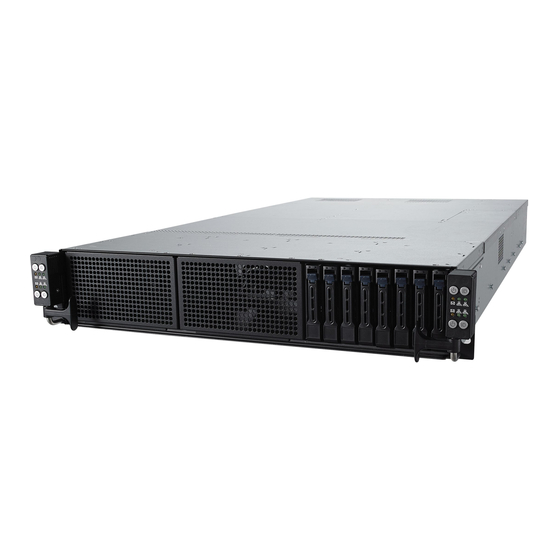
- Page 1 RS720Q-E9-RS8 RS720Q-E9-RS8-S 2U Rackmount Server User Guide...
- Page 2 ASUSTeK COMPUTER INC. (“ASUS”). ASUS provides this manual “as is” without warranty of any kind, either express or implied, including but not limited to the implied warranties or conditions of merchantability or fitness for a particular purpose. In no...
-
Page 3: Table Of Contents
Contents Notices ........................vii REACH ......................vii Safety information ....................viii Australia statement notice ................ix About this guide ......................x Chapter 1: Product Introduction System package contents ................. 1-2 Serial number label ..................1-3 System specifications ................1-4 Front panel features ................... 1-6 Rear panel features .................. - Page 4 Mid Plane jumper ..................4-16 Chapter 5: BIOS Setup Managing and updating your BIOS ............5-2 5.1.1 ASUS CrashFree BIOS 3 utility........... 5-2 5.1.2 ASUS EZ Flash Utility ..............5-3 5.1.3 BUPDATER utility ............... 5-4 BIOS setup program .................. 5-6 5.2.1...
- Page 5 Contents 5.5.6 Onboard LAN Configuration ............5-17 5.5.7 APM ..................5-18 5.5.8 PCI Subsystem Settings ............5-19 5.5.9 Network Stack Configuration............. 5-23 5.5.10 CSM Configuration ..............5-24 5.5.11 NVMe Configuration ..............5-25 5.5.12 USB Configuration ..............5-25 5.5.13 Vcore Adjust ................5-26 5.5.14 iSCSI Configuration ..............
- Page 6 ..........7-8 ® Installing the Intel I350-AM2/I210 Gigabit Adapters driver ....7-10 VGA driver installation ................7-13 ® Intel Rapid Storage Technology enterprise 5.0 installation ....7-15 Appendix Z11PH-D12 block diagram ..................A-2 ASUS contact information ..................A-3...
-
Page 7: Notices
(2) l’utilisateur de l’appareil doit accepter tout brouillage radioélectrique subi, même si le brouillage est susceptible d’en compromettre le fonctionnement. CAN ICES-3(A)/NMB-3(A) REACH Complying with the REACH (Registration, Evaluation, Authorization, and Restriction of Chemicals) regulatory framework, we publish the chemical substances in our products at ASUS REACH website at http://csr.asus.com/english/REACH.htm. -
Page 8: Safety Information
Safety information Electrical Safety • Before installing or removing signal cables, ensure that the power cables for the system unit and all attached devices are unplugged. • To prevent electrical shock hazard, disconnect the power cable from the electrical outlet before relocating the system. -
Page 9: Australia Statement Notice
If you require assistance please call ASUS Customer Service 1300 2787 88 or visit us at https://www.asus.com/support... -
Page 10: About This Guide
About this guide Audience This user guide is intended for system integrators, and experienced users with at least basic knowledge of configuring a server. Contents This guide contains the following parts: Chapter 1: Product Introduction This chapter describes the general features of the server, including sections on front panel and rear panel specifications. - Page 11 Refer to the following sources for additional information, and for product and software updates. ASUS Control Center (ACC) user guide This manual tells how to set up and use the proprietary ASUS server management utility. Visit asuscontrolcenter.asus.com for more information. ASUS websites The ASUS websites worldwide provide updated information for all ASUS hardware and software products.
-
Page 13: Chapter 1: Product Introduction
Chapter 1: Product Introduction Product Introduction This chapter describes the general features of the chassis kit. It includes sections on front panel and rear panel specifications. -
Page 14: System Package Contents
4 x System Fans (80mm x 38mm) 4 x System Fans (80mm x 38mm) 8 x Hot-swap 2.5” Storage Bays 8 x Hot-swap 2.5” Storage Bays 1 x ASUS RS720Q-E9-RS8 Series Support DVD (includes User Guide) 8 x CPU Heatsinks 1 x Bag of Screws Accessories... -
Page 15: Serial Number Label
Please take note of the product’s serial number. The Serial number contains 12 characters such as xxS0xxxxxxxx similar to the figure shown below. You need to provide the correct serial number to the ASUS Technical Support team member if you need assistance or, when requesting support. -
Page 16: System Specifications
System specifications The ASUS RS720Q-E9-RS8 Series is a 2U server system featuring the ASUS Z11PH-D12 ® ® Server Board. The server supports Intel Xeon processor Scalable family plus other latest technologies through the chipsets onboard. RS720Q-E9-RS8 RS720Q-E9-RS8-S Model Name 2 x Socket P0 (LGA 3647) per Node ®... - Page 17 Out of Band Solution Remote On-Board ASMB9-iKVM for KVM-over-IP Management OS support Please find the latest OS support from http://www.asus.com/ Regulatory Compliance BSMI, CE, C-TICK, FCC (ClassA) 800mm x 444mm x 88mm(2U) Dimension 31.5" x 17.48" x 3.46" Gross Weight Kg 41.5 kg...
-
Page 18: Front Panel Features
Front panel features The barebone server displays easily accessible features such as the power and reset buttons, LED indicators, and optical drive. Refer to the Front panel LEDs section for the LED descriptions. PORT80 PORT80 PORT80 PORT80 Turn off the system power and detach the power supply before removing or replacing any system component. -
Page 19: Rear Panel Features
When installing only two nodes, install the nodes to node slot number 1 and 3 or number 2 and 4. Z11PH-D12 (Node) DM management LAN port* LAN port 2 USB 3.0 ports Power button LAN port 1 Q-Code/Port 80 LED This port is for ASUS ASMB9-iKVM controller and for technicians only. RS720Q-E9-RS8 Series... -
Page 20: Internal Features
System fan (SYS_FAN4) BP_FAN1 (top) and BP_FAN2 (bottom) SATA/NVMe Mid-plane (for RS720Q-E9-RS8) or SATA/SAS/NVMe Mid-plane (for RS720Q-E9-RS8-S) ASUS Z11PH-D12 Server Board Power supply and power fan Ensure that the air duct is positioned on the gaps between the memory slots. -
Page 21: Led Information
LED information 1.7.1 Front panel LEDs LAN1 LED Location button with LED Power button with LED Message LED LAN2 LED LAN2 LED Message LED Power button with LED Location button with LED LAN1 LED PORT80 PORT80 Display PORT80 PORT80 Icon Description status PORT80... -
Page 22: Lan (Rj-45) Leds
1.7.2 LAN (RJ-45) LEDs LAN port LED indications ACT/LINK Activity/Link LED Speed LED SPEED Status Description Status Description No link 10 Mbps connection GREEN Linked ORANGE 100 Mbps connection BLINKING Data activity GREEN 1 Gbps connection LAN port 1.7.3 HDD status LEDs Status LED Active LED HDD LED... - Page 23 1.7.4 Q-Code table Action PHASE POST CODE TYPE DESCRIPTION Progress First post code(POWER_ON_POST_CODE) Progress Load BSP microcode(MICROCODE_POST_CODE) Security Phase Progress Set cache as ram for PEI phase(CACHE_ENABLED_POST_CODE) Progress CPU Early init.(CPU_EARLY_INIT_POST_CODE) Progress initializes South bridge for PEI preparation Progress PEI Core Entry Progress NB initialize before installed memory Progress...
- Page 24 Q-Code table Action PHASE POST CODE TYPE DESCRIPTION Progress DXE Core Started Progress DXE NVRAM Init. Progress SB run-time init. Progress DXE CPU Init Progress NB Init. DXE(Driver Progress NB Init. Execution Progress NB Init. Environment) phase Progress SB Init. Progress SB Init.
-
Page 25: Chapter 2: Hardware Information
Chapter 2: Hardware Information Hardware Information This chapter lists the hardware setup procedures that you have to perform when installing or removing system components. -
Page 26: Removing The Server Node
Removing the server node Remove the screw located on the node latch. Hold the server node lever and press the green node latch. Firmly pull the server node out of the server chassis. When installing only two nodes, install the nodes to node slot number 1 and 3 or number 2 and 4. -
Page 27: Air Duct
Air Duct The RS720Q-E9-RS8 series server system comes with a motherboard fan air duct to enable better air flow inside the motherboard while the system is running. Removing the air duct Remove the screws securing the air duct in place. Carefully lift the air duct out of the chassis. -
Page 28: Central Processing Unit (Cpu)
Contact your retailer immediately if the PnP cap is missing, or if you see any damage to the PnP cap/socket contacts/motherboard components. ASUS will shoulder the cost of repair only if the damage is shipment/ transit-related. - Page 29 Align the triangle mark on the CPU with the triangle mark on the CPU Carrier (A), install the CPU into the CPU Carrier until it clicks firmly into place (B), and CPU Carrier then install the CPU Carrier into the heatsink until it clicks firmly in place (C).
- Page 30 Twist each of the four screws with a screwdriver just enough to attach the heatsink to the motherboard. When the four screws are attached, tighten them one by one in the sequence 1, 2 then 3, 4 as shown on the heatsink to completely secure the heatsink. •...
-
Page 31: System Memory
GB, 128 GB LRDIMMS 3DS into the DIMM sockets using the memory configurations in this section. • Refer to ASUS Server AVL for the updated list of compatible DIMMs. • Always install DIMMs with the same CAS latency. For optimum compatibility, it is recommended that you obtain memory modules from the same vendor. - Page 32 To install two or more DIMMs, refer to the user guide bundled in the motherboard package. • Refer to www.asus.com for qualified vendor lists of the memory modules. Removing a DIMM from a single clip DIMM socket Press the retaining clip outward to unlock the DIMM.
-
Page 33: Storage Devices
Storage devices The system supports two (2) hot-swap storage devices per node. The storage device installed on the drive tray connects to the Mid Plane via the backplane. To install a hot-swap storage device: Ensure that the storage devices installed correspond to the correct node. For more information on the nodes and the storage bays, please refer to 1.4 Front panel features and 1.5 Rear panel features. - Page 34 Align and insert the 2.5-inch storage device and drive tray assembly into the drive bay. Repeat steps 1-6 to install the other 2.5-inch storage devices. 2-10 Chapter 2: Hardware Information...
-
Page 35: Expansion Slots
Expansion slots The following subsections describe the slots and expansion cards that they support. Ensure to unplug the power cord before adding or removing expansion cards. Failure to do so may cause you physical injury and damage motherboard components. 2.6.1 The PCI Express riser card The onboard PCI Express slot on the motherboard comes pre-installed with a riser card that supports one x16 slot (Gen3 x16 link) for installing PCI-E x16 low profile cards. - Page 36 Remove the screw from the metal bracket on the riser card, then remove the metal brackets from the riser card. Prepare the expansion card. Before installing an expansion card, read the documentation that came with it and ensure to make the necessary hardware settings. Align and insert the golden finger connectors of the expansion card to the PCI-E slot connector on the riser card as shown.
- Page 37 Align and insert the riser card and expansion card assembly into the PCI-E slot on the motherboard. The expansion card fits in one orientation only. If it does not fit, try reversing it. Secure the riser card with the screw that you removed earlier in step 1. RS720Q-E9-RS8 Series 2-13...
-
Page 38: Installing Mezzanine Cards
2.6.2 Installing Mezzanine cards To install a Mezzanine card: Locate a Mezzanine card connector on your motherboard. Prepare the Mezzanine card. Insert the port of the Mezzanine card into the mounting hole on the chassis then insert the golden connector of the Mezzanine card into the OCP connector on the motherboard. -
Page 39: Configuring An Expansion Card
2.6.3 Configuring an expansion card After installing the expansion card, configure it by adjusting the software settings. Turn on the system and change the necessary BIOS settings, if any. See Chapter 5 for information on BIOS setup. Assign an IRQ to the card. Refer to the Standard Interrupt assignments table for more information. -
Page 40: Backplane And Mid Plane Cabling
Backplane and Mid Plane cabling RS720Q-E9-RS8-S Backplane Upper Mid Plane Lower Mid Plane 2-16 Chapter 2: Hardware Information... - Page 41 Connect N4_MSASHD1 on the Backplane to N4_OCUSAS1 on the Upper Mid Plane Connect N3_MSASHD1 on the Backplane to N3_OCUSAS1 on the Lower Mid Plane Connect N2_MSASHD1 on the Backplane to N2_OCUSAS1 on the Upper Mid Plane Connect N1_MSASHD1 on the Backplane to N1_OCUSAS1 on the Lower Mid Plane Connect N4_OCUPCIE2 on the Backplane to N4_OCUPCIE2 on the Upper Mid Plane...
- Page 42 RS720Q-E9-RS8 Backplane Upper Mid Plane Lower Mid Plane 2-18 Chapter 2: Hardware Information...
- Page 43 Connect N4_MSASHD1 on the Backplane to N4_OCUSATA1 on the Upper Mid Plane Connect N3_MSASHD1 on the Backplane to N3_OCUSATA1 on the Lower Mid Plane Connect N2_MSASHD1 on the Backplane to N2_OCUSATA1 on the Upper Mid Plane Connect N1_MSASHD1 on the Backplane to N1_OCUSATA1 on the Lower Mid Plane Connect N4_OCUPCIE2 on the Backplane to N4_OCUPCIE2 on the Upper Mid Plane...
-
Page 44: Removable/Optional Components
Removable/optional components You may need to remove previously installed system components when installing or removing system devices. Or you may need to install the optional components into the system. This section tells how to remove/install the following components: System fans Power supply module Ensure that the system is turned off before removing any components. - Page 45 Prepare a replacement fan of the same type and size. Disconnect the system fan cable from the fan connector on the Mid Plane. Lift the fan then set it aside. Repeat steps 3 to 4 to uninstall the other system fans. RS720Q-E9-RS8 Series 2-21...
-
Page 46: Power Supply Module
2.8.2 Power supply module To replace a power supply unit (PSU): Lift up the PSU lever. Hold the PSU lever, press the PSU latch (A) then carefully pull the PSU out of the system chassis (B). Prepare the replacement PSU. Align and insert the replacement PSU into the empty PSU bay until it clicks in place. - Page 47 • The system automatically combines the two power supply modules as a single one. The combined output power varies with input voltages. Refer to the table below for details. 1600W Input Voltage Max. Output Power (Watt) per PSU 200V-240Vac, 9.5A, 47-63Hz 1600W 2200W Input Voltage...
- Page 48 2-24 Chapter 2: Hardware Information...
-
Page 49: Chapter 3: Installation Options
Chapter 3: Installation Options Installation Options This chapter describes how to install the optional components and devices into the barebone server. -
Page 50: Tool-Less Friction Rail Kit
Tool-less Friction Rail Kit The tool less design of the rail kit allows you to easily install the rack rails into the server rack without the need for additional tools. The kit also comes with a metal stopping bracket that can be installed to provide additional support and stability to the server. - Page 51 Select a desired space and place the appropriate rack rail (left and right) on opposite positions on the rack. A 1U space is consists of three square mounting holes with two thin lips on the top and the bottom. Press the spring lock then insert the studs into the selected square mounting holes on the rack post.
-
Page 52: Rail Kit Dimensions
Lift the server chassis and insert into the rack rail. • Ensure that the rack rail cabinet and the rack posts are stable and standing firmly on a level surface. • We strongly recommend that at least two able-bodied persons perform the steps described in this guide. • We recommend the use an appropriate lifting tool or device, if necessary. Ensure to include the side knots on the two sides of the server in the rack rail holders. The illustrations shown above are for reference only. - Page 53 Chapter 4: Motherboard Information Motherboard Information This chapter includes the motherboard layout and brief descriptions of the jumpers and internal connectors.
-
Page 54: Motherboard And Mid Plane Layout
Motherboard and Mid plane layout Z11PH-D12 Chapter 4: Motherboard Information... - Page 55 RS720Q-E9-RS8-S Mid Plane RS720Q-E9-RS8 Mid Plane RS720Q-E9-RS8 Series...
-
Page 56: Layout Contents
4.1.1 Layout contents Jumpers Page Clear RTC RAM (CLRTC1) VGA controller setting (3-pin VGA_SW1) LAN controller setting (3-pin LAN_SW1, LAN_SW2) ME firmware force recovery setting (3-pin ME_RCVR1) DDR4 thermal event setting (3-pin DIMMTRIP1-2) BMC Setting (3-pin BMC_EN1) PMBus 1.2 PSU select jumper (3-pin SMART_PSU1) Chassis Intrusion (2-pin INTRUSION1) DMLAN setting (3-pin DM_IP_SEL1) 10. -
Page 57: Jumpers
Jumpers Clear RTC RAM (CLRTC1) This jumper allows you to clear the Real Time Clock (RTC) RAM in CMOS. You can clear the CMOS memory of date, time, and system setup parameters by erasing the CMOS RTC RAM data. The onboard button cell battery powers the RAM data in CMOS, which include system setup information such as system passwords. -
Page 58: Vga Controller Setting (3-Pin Vga_Sw1)
VGA controller setting (3-pin VGA_SW1) This jumper allows you to enable or disable the onboard VGA controller. Set to pins 1–2 to activate the VGA feature. LAN controller setting (3-pin LAN_SW1, LAN_SW2) ® These jumpers allow you to enable or disable the onboard Intel I210AT Gigabit LAN controllers. -
Page 59: Me Firmware Force Recovery Setting (3-Pin Me_Rcvr1)
ME firmware force recovery setting (3-pin ME_RCVR1) This jumper allows you to quickly recover the Intel Management Engine (ME) firmware when it becomes corrupted. DDR4 thermal event setting (3-pin DIMMTRIP1-2) These jumpers allow you to enable or disable DDR4 DIMM thermal sensing event pin. RS720Q-E9-RS8 Series... -
Page 60: Bmc Setting (3-Pin Bmc_En1)
BMC Setting (3-pin BMC_EN1) This jumper allows you to enable or disable the ASMB9. PMBus 1.2 PSU select jumper (3-pin SMART_PSU1) This jumper allows you to select PSU PMBus version. Chapter 4: Motherboard Information... -
Page 61: Chassis Intrusion (2-Pin Intrusion1)
Chassis Intrusion (2-pin INTRUSION1) These leads are for the intrusion detection feature for chassis with intrusion sensor or microswitch. When you remove any chassis component, the sensor triggers and sends a high level signal to these leads to record a chassis intrusion event. The default setting is short CHASSIS# and GND pin by jumper cap to disable the function. -
Page 62: Pch_Mfg Setting (3-Pin Pch_Mfg1)
PCH_MFG setting (3-pin PCH_MFG1) This jumper allows you to update the BIOS ME block. 4-10 Chapter 4: Motherboard Information... -
Page 63: Internal Connectors
Internal connectors Trusted Platform Module connector (20-1 pin TPM) This connector supports a Trusted Platform Module (TPM) system, which can securely store keys, digital certificates, passwords, and data. A TPM system also helps enhance network security, protects digital identities, and ensures platform integrity. Serial port connector (10-1 pin COM1) This connector is for a serial (COM) port. -
Page 64: Vroc_Key Connector (4-Pin Vroc_Key1)
VROC_KEY connector (4-pin VROC_KEY1) This connector allows you to connect a KEY module to enable CPU RAID functions with Intel CPU RSTe. ® The KEY module is purchased separately. VGA connector (16-1 pin VGA_HDR1) This connector supports the VGA High Dynamic-Range interface. 4-12 Chapter 4: Motherboard Information... -
Page 65: Mezzanine Pci Card Connectors (Mezzpcie1; Mezzpcie2)
Mezzanine PCI card connectors (MEZZPCIE1; MEZZPCIE2) The MEZZPCIE1, MEZZPCIE2, and MEZZKR1 connectors support Open Compute Project (OCP) cards. Power connector This power connector connects to the Mid Plane. RS720Q-E9-RS8 Series 4-13... -
Page 66: Internal Leds
The green heartbeat LED blinks per second to indicate that the ASMB9 is working normally. • The heartbeat LED functions only when you enable the ASUS ASMB9. • Every time after the AC power is replugged, you have to wait for about 30 seconds for the system to power up. -
Page 67: Message Led (Mesled1)
Message LED (MESLED1) This onboard LED lights up to red when there is temperature warning or a BMC event log is generated. Location LED (LOCLED1) This onboard LED lights up when the Location button on the server is pressed or when triggered by a system management software. -
Page 68: Mid Plane Jumper
Mid Plane jumper The illustration in this section may differ between models, but the location of the jumper remains the same. 12V_SEL1 jumper This jumper allows you to enhance the 12V standy when the system’s +12VSB is not enough. 4-16 Chapter 4: Motherboard Information... -
Page 69: Chapter 5: Bios Setup
Chapter 5: BIOS Setup BIOS Setup This chapter tells how to change the system settings through the BIOS Setup menus. Detailed descriptions of the BIOS parameters are also provided. -
Page 70: Managing And Updating Your Bios
BIOS in the future. Copy the original motherboard BIOS using the BUPDATER utility. 5.1.1 ASUS CrashFree BIOS 3 utility The ASUS CrashFree BIOS 3 is an auto recovery tool that allows you to restore the BIOS file when it fails or gets corrupted during the updating process. You can update a corrupted BIOS file using a USB flash drive that contains the updated BIOS file. -
Page 71: Asus Ez Flash Utility
5.1.2 ASUS EZ Flash Utility The ASUS EZ Flash Utility feature allows you to update the BIOS without having to use a DOS-based utility. Before you start using this utility, download the latest BIOS from the ASUS website at www. asus.com. To update the BIOS using EZ Flash Utility: Insert the USB flash disk that contains the latest BIOS file into the USB port. Enter the BIOS setup program. Go to the Tool menu then select ASUS EZ Flash Utility. -
Page 72: Bupdater Utility
The BUPDATER utility allows you to update the BIOS file in the DOS environment using a bootable USB flash disk drive with the updated BIOS file. Updating the BIOS file To update the BIOS file using the BUPDATER utility: Visit the ASUS website at www.asus.com and download the latest BIOS file for the motherboard. Save the BIOS file to a bootable USB flash disk drive. Copy the BUPDATER utility (BUPDATER.exe) from the ASUS support website at support.asus.com to the bootable USB flash disk drive you created earlier. Boot the system in DOS mode, then at the prompt, type: BUPDATER /i[filename].CAP where [filename] is the latest or the original BIOS file on the bootable USB flash disk drive, then press <Enter>. A:\>BUPDATER /i[file name].CAP Chapter 5: BIOS Setup... - Page 73 The utility verifies the file, then starts updating the BIOS file. ASUS Tek. EzFlash Utility Current Platform New Platform Platform : Z11PH-D12 Platform : Z11PH-D12 Version : 0301 Version : 0304 Build date: 11/05/2017 Build date: 11/22/2017 Start Programming Flash. DO NOT SHUTDOWN THE SYSTEM!!! Write DO NOT shut down or reset the system while updating the BIOS to prevent system boot failure! The utility returns to the DOS prompt after the BIOS update process is completed.
-
Page 74: Bios Setup Program
<F5> and select Yes to load the BIOS default settings. • The BIOS setup screens shown in this section are for reference purposes only, and may not exactly match what you see on your screen. • Visit the ASUS website (www.asus.com) to download the latest BIOS file for this motherboard. The system then runs the power-on self-test or POST. While the tests are running, the BIOS beeps or additional messages appear on the screen. If you do not see anything within 30 seconds from the time you turned on the power, the system may have failed a power-on test. -
Page 75: Bios Menu Screen
5.2.1 BIOS menu screen Menu items Menu bar Configuration fields General help Navigation keys 5.2.2 Menu bar The menu bar on top of the screen has the following main items: Main For changing the basic system configuration For changing the performance settings Performance Tuning For changing the advanced system settings Advanced For changing the platform settings Platform Configuration... -
Page 76: Menu Items
5.2.3 Menu items The highlighted item on the menu bar displays the specific items for that menu. For example, selecting Main shows the Main menu items. The other items (Advanced, Platform Configuration, Socket Configuration, Event Logs, Server Mgmt, Security, Boot, Tool, and Save & Exit) on the menu bar have their respective menu items. 5.2.4 Submenu items A solid triangle before each item on any menu screen means that the item has a submenu. To display the submenu, select the item then press <Enter>. 5.2.5 Navigation keys At the bottom right corner of a menu screen are the navigation keys for the BIOS setup program. Use the navigation keys to select items in the menu and change the settings. 5.2.6 General help At the top right corner of the menu screen is a brief description of the selected item. -
Page 77: Main Menu
Main menu When you enter the BIOS Setup program, the Main menu screen appears. The Main menu provides you an overview of the basic system information, and allows you to set the system date, time, language, and security settings. 5.3.1 System Date [Day xx/xx/xxxx] Allows you to set the system date. 5.3.2 System Time [xx:xx:xx] Allows you to set the system time. RS720Q-E9-RS8 Series... -
Page 78: Performance Tuning Menu
Performance Tuning menu The Performance Tuning menu items allow you to change performance related settings for different scenarios. Optimized Performance Setting [Default] Allows you to select performance settings for different scenarios. [Default] Default settings. [By Benchmark] O ptimize for different kinds of benchmarks. Select this option, then select a benchmark type from the >> list. [By Workload] O ptimize for different kinds of workloads. Select this option, then select a workload type from the >>... - Page 79 Engine Boost [Disabled] Enable this item to boost the CPU's frequency. Configuration options: [Disabled] [Level1] [Level2] [Level3(Max)] Overclocking [Disabled] Enable this item to increase the CPU’s clock. Configuration options: [Disabled] [Level1] [Level2] [Level3(Max)] Operate with an ambient temperature of 25 C or lower for optimized performance. Please note that overclocking might cause component damage or system crashes, which may reduce the lifespan of the system and the CPU. Use this tool at your own risk. Power Balancer [Disabled] Select [Enable Auto] to dynamically adjust the frequency of all CPU cores based on the current utilization, delivering better performance per watt for improved system energy efficiency. Configuration options: [Disabled] [Enable Auto] [Enable Manual] RS720Q-E9-RS8 Series 5-11...
-
Page 80: Advanced Menu
Take caution when changing the settings of the Advanced menu items. Incorrect field values can cause the system to malfunction. Optimized Performance Settings [Default] This option allows you to select a recommended BIOS setting to optimize performance. Asus Turbo Ratio Lock (ATRL) [Disabled] Allows you to keep the processor operating at the turbo highest frequency for maximum performance. Configuration options: [Disabled] [Enabled] 5-12 Chapter 5: BIOS Setup... -
Page 81: Trusted Computing
5.5.1 Trusted Computing Configuration Security Device Support [Enabled] Allows you to enable or disable the BIOS support for security device. Configuration options: [Disabled] [Enabled] 5.5.2 ACPI Settings Enable ACPI Auto Configuration [Disabled] Allows you to enable or disable the BIOS ACPI Auto Configuration. Configuration options: [Disabled] [Enabled] Enable Hibernation [Enabled] Allows you to enable or disable the ability of the system to hibernate (OS/Sleep State). Configuration options: [Disabled] [Enabled] This option may be not effective with some OS. -
Page 82: Super Io Configuration
5.5.4 Super IO Configuration Serial Port 1 Configuration Allows you to set the parameters of Serial Port 1. Serial Port [Enabled] Allows you to enable or disable Serial Port. Configuration options: [Disabled] [Enabled] The following item appears only when you set Serial Port to [Enabled]. Change Settings [Auto] Allows you to choose the setting for Super IO device. - Page 83 The following item appears only when you set Console Redirection to [Enabled]. Console Redirection Settings This item becomes configurable only when you enable the Console Redirection item. The settings specify how the host computer and the remote computer (which the user is using) will exchange data. Both computers should have the same or compatible settings. Terminal Type [VT-UTF8] Allows you to set the terminal type.
- Page 84 Flow Control [Hardware RTS/CTS] Flow control can prevent data loss from buffer overflow. When sending data, if the receiving buffers are full, a “stop” signal can be sent to stop the data flow. Once the buffers are empty, a “start” signal can be sent to re-start the flow. Hardware flow control uses two wires to send start/stop signals. Configuration options: [None] [Hardware RTS/CTS] VT -UTF8 Combo Key Support [Enabled] This allows you to enable the VT -UTF8 Combination Key Support for ANSI/VT100 terminals. Configuration options: [Disabled] [Enabled] Recorder Mode [Disabled] With this mode enabled only text will be sent. This is to capture Terminal data. Configuration options: [Disabled] [Enabled] Legacy OS Redirection Resolution [80x24] This allows you to set the number of rows and columns supported on the Legacy OS. Configuration options: [80x24] [80x25] Putty Keypad [VT100] This allows you to select the FunctionKey and Keypad on Putty. Configuration options: [VT100] [LINUX] [XTERMR6] [SCO] [ESCN] [VT400] Redirection After BIOS POST [Always Enable] This setting allows you to specify if Bootloader is selected than Legacy console...
-
Page 85: Onboard Lan Configuration
The following item appears only when you set Console Redirection to [Enabled]. Console Redirection Settings Out-of-Band Mgmt Port [COM1] Microsoft Windows Emergency Management Services (EMS) allow for remote management of a Windows Server OS through a serial port. Configuration options: [COM1] [COM2] Terminal Type [VT-UTF8] Microsoft Windows Emergency Management Services (EMS) allow for remote management of a Windows Server OS through a serial port. Configuration options: [VT100] [VT100+] [VT-UTF8] [ANSI] Bits per second [115200] Microsoft Windows Emergency Management Services (EMS) allow for remote management of a Windows Server OS through a serial port. Configuration options: [9600] [19200] [57600] [115200] Flow Control [None] Microsoft Windows Emergency Management Services (EMS) allow for remote management of a Windows Server OS through a serial port. Configuration options: [None] [Hardware RTS/CTS] [Software Xon/Xoff] 5.5.6 Onboard LAN Configuration... -
Page 86: Apm
The following item appears only when you set Intel LAN1 Enable to [Enabled]. Intel LAN ROM Type [PXE] Allows you to select the Intel LAN ROM type. Configuration options: [Disabled] [PXE] [iSCSI] ® Due to Intel limitations, both Intel LAN ROM Type options should be the same when [PXE] or [iSCSI] is selected. Intel LAN2 Enable [Enabled] Allows you to enable or disable the Intel LAN. Configuration options: [Disabled] [Enabled] The following item appears only when you set Intel LAN2 Enable to [Enabled]. Intel LAN2 ROM Type [Disabled] Allows you to select the Intel LAN ROM type. -
Page 87: Pci Subsystem Settings
5.5.8 PCI Subsystem Settings Allows you to configure PCI, PCI-X, and PCI Express Settings. Load RT32 Image [Disabled] Allows you to enable or disable RT32 Image Loading. Configuration options: [Disabled] [Enabled] Above 4G Decoding [Disabled] Allows you to enable or disable 64-bit capable devices to be decoded in above 4G address space. It only works if the system supports 64-bit PCI decoding. Configuration options: [Disabled] [Enabled] The following item appears only when you set Above 4G Decoding to [Enabled]. First VGA 4G Decode [Auto] This option enables or disables 64-bit capable devices to be decoded in above 4G address space (only if system supports 64-bit PCI decoding). - Page 88 No Snoop [Enabled] This option allows you to enable or disable PCI Express Device No Snoop option. Configuration options: [Disabled] [Enabled] Maximum Payload [Auto] This option allows you to set the Maximum Payload of PCI Express Device or allow System BIOS to select the value. Configuration options: [Auto] [128 Bytes] [256 Bytes] [512 Bytes] [1024 Bytes] [2048 Bytes] [4096 Bytes] Maximum Read Request [Auto]...
- Page 89 PCI Express Gen 2 Settings PCI Express GEN2 Device Register Settings Completion Timeout [Default] This option allows system software to modify the Completion Timeout value for device Functions which support Completion Timeout programmability. [Default] 50us to 50ms. [Shorter] Shorter timeout ranges supported by hardware will be used. [Longer] Longer timeout ranges supported by hardware will be used. [Disabled] Disable Completion Timeout.
- Page 90 PCI Express GEN2 Device Register Settings Target Link Speed [Auto] If supported by hardware and set to Force to X.X GT/s, for Downstream Ports, this sets an upper limit on Link operational speed by restricting the values advertised by the Upstream component in its training sequences. When Auto is selected HW initialized data will be used. Configuration options: [Auto] [Force to 2.5 GT/s] [Force to 5.0 GT/s] [Force to 8.0 GT/s] Clock Power Management [Disabled] If supported by hardware and set to Enabled, the device is permitted to use CLKREQ# signal for power management of Link clock in accordance to protocol defined in appropriate form factor specification. Configuration options: [Disabled] [Enabled] Compliance SOS [Disabled] If supported by hardware and set to Enabled, this will force LTSSM to send SKP Ordered Sets between sequences when sending Compliance Pattern or Modified Compliance Pattern. Configuration options: [Disabled] [Enabled] Hardware Autonomous Width [Enabled] If supported by hardware and set to Disabled, this will disable the hardware’s ability to change link width except for width size reduction for the purpose of correcting unstable link operation.
-
Page 91: Network Stack Configuration
5.5.9 Network Stack Configuration Allows you to configure the network stack configuration. Network Stack [Disabled] Allows you to enable or disable UEFI Network Stack. Configuration options: [Disabled] [Enabled] The following items appear only when you set Network Stack to [Enabled]. Ipv4 PXE Support [Disabled] Enables or disables the Ipv4 PXE Boot Support. If disabled, Ipv4 PXE boot option will not be created. Configuration options: [Disable] [Enable] Ipv4 HTTP Support [Disabled] Enables or disables the Ipv4 HTTP Boot Support. If disabled, Ipv4 PXE boot option will not be created. Configuration options: [Disable] [Enable] Ipv6 PXE Support [Disabled] Enables or disables the Ipv6 PXE Boot Support. If disabled, Ipv6 PXE boot option will not be created. -
Page 92: Csm Configuration
5.5.10 CSM Configuration CSM Support [Enabled] This option allows you to enable or disable CSM Support. Configuration options: [Disabled] [Enabled] The following items appear only when you set CSM Support to [Enabled]. GateA20 Active [Upon Request] This allows you to set the GA20 option. [Upon Request] GA20 can be disabled using BIOS services. -
Page 93: Nvme Configuration
Other PCI devices [Legacy] This item determines the OpROM execution policy for devices other than Network, Storage, or Video. Configuration options: [UEFI ] [Legacy] 5.5.11 NVMe Configuration You may view the NVMe controller and Drive information if an NVMe device is connected. 5.5.12 USB Configuration Legacy USB Support [Enabled] [Disabled] The USB devices can be used only for the BIOS setup program. It cannot be recognized in boot devices list. [Enabled] Enables the support for USB devices on legacy operating systems (OS). -
Page 94: Vcore Adjust
5.5.13 Vcore Adjust CPU1 / CPU2 Configuration options: [AUTO] [0.3438] [0.3320] [0.3203] [0.3086] [0.3008] [0.2969] [0.2852] [0.2734] [0.2617] [0.2500] [0.2383] [0.2266] [0.2148] [0.2031] 5.5.14 iSCSI Configuration Allows you to configure the iSCSi parameters. 5.5.15 Intel(R) Virtual RAID on CPU Allows you to configure the view the RAID volumes and VMD controllers on the system. 5-26 Chapter 5: BIOS Setup... -
Page 95: Platform Configuration Menu
Platform Configuration menu The IntelRCSetup menu items allow you to change the platform settings. Take caution when changing the settings of the Platform Configuration menu items. Incorrect field values can cause the system to malfunction. 5.6.1 PCH Configuration PCH Devices Board Capability [DeepSx] [SUS_PWR_DN_ACK] Send Disabled to PCH. [DeepSx] Show DeepSx Policies. DeepSx Power Policies [Disabled] Allows you to configure the DeepSx Mode configuration. Configuration options: [Disabled] [Enabled in S5] [Enabled in S4 and S5] GP27 Wake From DeepSx [Disabled] Allows you to enable or disable GP27 Wake From DeepSx. Configuration options: [Disabled] [Enabled] PCI Express Configuration PCI-E ASPM Support (Global) [L1 Only]... - Page 96 USB Configuration USB Precondition [Disabled] Allows you to enable or disable precondition work on USB host controller and root ports for faster enumeration. Configuration options: [Disabled] [Enabled] XHCI Manual Mode [Disabled] This option is used by validation. Configuration options: [Disabled] [Enabled] The following items appear only when XHCI Manual Mode is set to [Enabled]. Trunk Clock Gating (BTCG) [Enabled] Allows you to enable or disable BTCG. Configuration options: [Disabled] [Enabled] Enable USB 3.0 pins [Disable all pins] Allows you to enable or disable USB 3.0 pins or on a per pin basis.
-
Page 97: Miscellaneous Configuration
5.6.2 Miscellaneous Configuration Active Video [Offboard Device] Allows you to select the video type. Configuration options: [Onboard Device] [Offboard Device] PMTT ACPI Table [Disabled] Allows you to enable or disable PMTT ACPI Table for DDR4 only. Configuration options: [Disabled] [Enabled] 5.6.3 Server ME Configuration Displays the Server ME Technology parameters on your system. Navigate to the second page of the screen to see the rest of items in this menu by pressing the Up or Down arrow keys. -
Page 98: Runtime Error Logging
5.6.4 Runtime Error Logging Displays the Server ME Technology parameters on your system. System Errors [Enabled] This item allows you to enable or disable System Errors. Configuration options: [Disabled] [Enabled] The following item is configurable only when System Errors is set to [Enabled]. Whea Settings Whea Support [Enabled] This item allows you to enable or disable the WHEA support. Configuration options: [Disabled] [Enabled] 5-30 Chapter 5: BIOS Setup... -
Page 99: Socket Configuration Menu
Socket Configuration menu The IntelRCSetup menu items allow you to change the socket settings. 5.7.1 Processor Configuration Navigate to the second page of the screen to see the rest of items in this menu by pressing the Up or Down arrow keys. To quickly go to the last item of the second page, press the Page Down button. Press the Page Up button to go back to the first item in the first page. Hyper-threading [ALL] [Enabled] This item allows a hyper-threading processor to appear as two logical processors, allowing the operating system to schedule two threads or processors simultaneously. Configuration options: [Disabled] [Enabled] RS720Q-E9-RS8 Series 5-31... - Page 100 Execute Disable Bit [Enabled] XD can prevent certain classes of malicious buffer overflow attacks when combined with a supporting OS (Windows Server 2003 SP1, Windows XP SP2, SuSE Linux 9.2, Redhat Enterprise 3 Update 3). Configuration options: [Disabled] [Enabled] Enable Intel(R) TXT [Disabled] Forces the XD feature log to always return 0 when disabled. Configuration options: [Disabled] [Enabled] VMX [Enabled] Enables the Vanderpool Technology. Takes effect after reboot. Configuration options: [Disabled] [Enabled] Enable SMX [Disabled] Enables the Safer Mode Extensions. Configuration options: [Disabled] [Enabled] Hardware Prefetcher [Enabled] This Item allows you to turn on/off the mid level cache(L2) streamer prefetcher. Configuration options: [Disabled] [Enabled] Adjacent Cache Prefetch [Enabled] This Item allows you to turn on/off prefetching of adjacent cache lines. Configuration options: [Disabled] [Enabled] DCU Streamer Prefetcher [Enabled] This Item allows you to enable or disable prefetcher of next L1 data line.
-
Page 101: Common Refcode Configuration
5.7.2 Common RefCode Configuration Numa [Enabled] This item enables or disables the Non uniform Memory Access (NUMA). Configuration options: [Disabled] [Enabled] 5.7.3 UPI Configuration UPI General Configuration UPI Status This item displays information about the UPI status. Link Speed Mode [Fast] This item allows you to select the UPI link speed as either the fast mode or slow mode. Configuration options: [Slow] [Fast] Link Frequency Select [Auto] This item allows for selecting the UPI link frequency. -
Page 102: Memory Configuration
5.7.4 Memory Configuration Enforce POR [Auto] Allows you to enforce POR restrictions for DDR4 frequency and voltage programming. Configuration options: [Auto] [POR] [Disabled] Memory Frequency [Auto] Allows you to select the memory frequency setting. Configuration options: [Auto] [2133] [2400] [2666] Data Scrambling for DDR4 [Auto] Allows you to enable or disable data scrambling. Configuration options: [Auto] [Disabled] [Enabled] Memory Topology Displays memory topology with DIMM population information. -
Page 103: Iio Configuration
Memory RAS Configuration Mirror mode [Disabled] Allows you to select Mirror modes. Mirror mode will set entire 1LM/2LM memory in system to be mirrored, consequently reducing the memory capacity by half. Enabling Mirror mode will disable XPT Prefetch. Configuration options: [Disabled] [Mirror Mode 1LM] [Mirror Mode 2LM] Mirror TAD0 [Disabled] Allows you to enable or disable Mirror on entire memory for TAD0. Configuration options: [Disabled] [Enabled] Enable Partial Mirror [Disabled] Partial mirror mode will enable the required size of memory to be mirrored. If rank sparing is enabled, partial mirroring will not take effect. Mirror Enable will disable XPT Prefetch. Configuration options: [Disabled] [Enabled] UEFI ARM Mirror [Disabled] Allows you to enable or disable UEFI ARM Mirror. Configuration options: [Disabled] [Enabled] Memory Rank Sparing [Disabled] Allows you to enable or disable Memory Rank Sparing... -
Page 104: Advanced Power Management Configuration
IIO-PCIE Express Global Options PCIE relaxed Ordering [Enabled] Allows you to enable or disable PCIE relaxed Ordering. Configuration options: [Disabled] [Enabled] 5.7.6 Advanced Power Management Configuration CPU P State Control Boot performance mode [Max Performance] Allows you to switch between Boot performance mode. Configuration options: [Max Performance] [Max Efficient] [Set by Intel Node Manager] Energy Efficient Turbo [Enabled] Allows you to enable or disable Energy Efficient Turbo. - Page 105 Package C State Control Package C State [Auto] Allows you to select Package C State. Configuration options: [C0/C1 state] [C3 state] [C6(non Retention) state] [C6(Retention) state] [No Limit] [Auto] CPU Thermal Management CPU T State Control Software Controlled T-States [Disabled] Allows you to enable or disable Software Controlled T-States. Configuration options: [Disabled] [Enabled] The following item appears only when Software Controlled T-States is set to [Enabled]. T-State Throttle Level [Disabled] Allows you to set the T-State Throttle level.
-
Page 106: Event Logs Menu
P0 TotalTimeThreshold Low [23] The HW switching mechanism DISABLES the performance setting (0) when the total P0 time is less than the threshold set. Configuration options: [0] - [99] P0 TotalTimeThreshold High [3a] The HW switching mechanism Enables the performance setting (0) when the total P0 time is greater than the threshold set. Configuration options: [0] - [99] Event Logs menu 5.8.1 Change Smbios Event Log Settings Press <Enter> to change the Smbios Event Log configuration. All values changed here do not take effect until computer is restarted. Enabling/Disabling Options Smbios Event Log [Enabled] Change this to enable or disable all features of Smbios Event Logging during boot. -
Page 107: Server Mgmt Menu
Server Mgmt menu OS Watchdog Timer [Disabled] This item allows you to start a BIOS timer which can only be shut off by Intel Management Software after the OS loads. Configuration options: [Disabled] [Enabled] The following items are configurable only when OS Watchdog Timer is set to [Enabled]. OS Wtd Timer Timeout [10 minutes] Allows you to configure the length for the OS Boot Watchdog Timer. -
Page 108: Bmc Network Configuration
5.9.2 BMC network configuration The sub-items in this configuration allow you to configure the BMC network parameters. Navigate to the second page of the screen to see the rest of items in this menu by pressing the Up or Down arrow keys. To quickly go to the last item of the second page, press the Page Down button. Press the Page Up button to go back to the first item in the first page. IPV4 DM_LAN1/ Shared LAN Config Address source [Previous State] This item allows you to configure LAN channel parameters statistically or dynamically (by BIOS or BMC). Unspecified option will not modify any BMC network parameters during BIOS phase. -
Page 109: View System Event Log
Config Address source [Previous State] This item allows you to configure LAN channel parameters statistically or dynamically (by BIOS or BMC). Unspecified option will not modify any BMC network parameters during BIOS phase. Configuration options: [Previous State] [Static] [DynamicBmcDhcp] [DynamicBmcNonDhcp] 5.9.3 View System Event Log This item allows you to view the system event log records. RS720Q-E9-RS8 Series 5-41... -
Page 110: Security Menu
5.10 Security menu This menu allows a new password to be created or a current password to be changed. The menu also enables or disables the Secure Boot state and lets the user configure the System Mode state. Administrator Password To set an administrator password: 1. Select the Administrator Password item and press <Enter>. 2. From the Create New Password box, key in a password, then press <Enter>. 3. Confirm the password when prompted. - Page 111 User Password To set a user password: 1. Select the User Password item and press <Enter>. 2. From the Create New Password box, key in a password, then press <Enter>. 3. Confirm the password when prompted. To change a user password: 1. Select the User Password item and press <Enter>. 2. From the Enter Current Password box, key in the current password, then press <Enter>. 3. From the Create New Password box, key in a new password, then press <Enter>. 4. Confirm the password when prompted. To clear a user password: 1.
- Page 112 Key Management This item only appears when the item Secure Boot Mode is set to [Custom]. The Key Management item allows you to modify Secure Boot variables and set Key Management page. Provision Factory Defaults [Disabled] Allows you to provision factory default Secure Boot keys when the system is in Setup Mode. Configuration options: [Disabled] [Enabled] Install Factory Default keys This item will install all Factory Default keys. Reset to Setup Mode This item appears only when you load the default Secure Boot keys. This item allows you to clear all default Secure Boot keys. Enroll Efi Image This item will allow the image to run in Secure Boot mode. Save All Secure Boot Variables This item will ask you if you want to save all secure boot variables. Select Yes if you want to save all secure boot variables, otherwise select No.
-
Page 113: Boot Menu
These items specify the boot device priority sequence from the available devices. The number of device items that appears on the screen depends on the number of devices installed in the system. • To select the boot device during system startup, press <F8> when ASUS Logo appears. • To access Windows OS in Safe Mode, please press <F8> after POST. Network Device BBS Priorities / Hard Drive BBS Priorities These items allow you to set the booting order of the devices. -
Page 114: Tool Menu
<Enter> to display the submenu. IPMI HWM Allows you to run the IPMI hardware monitor. Start EzFlash Allows you to run ASUS EzFlash BIOS ROM Utility when you press <Enter>. Refer to the ASUS EzFlash Utility section for details. 5.13 Save & Exit menu The Exit menu items allow you to save or discard your changes to the BIOS items. - Page 115 Boot Override These items displays the available devices. The device items that appears on the screen depends on the number of devices installed in the system. Click an item to start booting from the selected device. Launch EFI Shell from filesystem device This item allows you to attempt to launch the EFI Shell application (shellx64.efi) from one of the available filesystem devices. RS720Q-E9-RS8 Series 5-47...
- Page 116 5-48 Chapter 5: BIOS Setup...
-
Page 117: Chapter 6: Raid Configuration
Chapter 6: RAID Configuration RAID Configuration This chapter provides instructions for setting up, creating, and configuring RAID sets using the available utilities. -
Page 118: Setting Up Raid
Setting up RAID ® The motherboard supports the Intel Rapid Storage Technology enterprise Option ROM Utility with RAID 0, RAID 1, RAID 10, and RAID 5 support (for Windows OS and Linux). 6.1.1 RAID definitions RAID 0 (Data striping) optimizes two identical hard disk drives to read and write data in parallel, interleaved stacks. -
Page 119: Intel ® Virtual Raid On Cpu In Bios
Intel Virtual Raid on CPU in BIOS ® This feature allows you to do CPU RAID functions with Intel CPU RSTe. ® ® • Due to chipset behavior, enabling the Intel RSTe CPU RAID functions requires an ® Intel VROC hardware key module. •... -
Page 120: Creating A Raid Set
Go to the Save & Exit menu > Save Changes and Reset, or press <F10> to save and reset. Enter the BIOS Setup again during POST. Go to the Advanced menu > Intel(R) Virtual Raid on CPU > All Intel VMD ®... -
Page 121: Deleting A Raid Set
When the Strip Size item is selected, press <Enter> to select strip size for the RAID array (for RAID 0, 10 and 5 only), and then press <Enter>. The available strip size values range from 4 KB to 128 KB. The following are typical values: RAID 0: 128 KB RAID 10: 64 KB RAID 5: 64 KB... -
Page 122: Intel ® Rapid Storage Technology Enterprise (Windows)
® Intel Rapid Storage Technology enterprise (Windows) The Intel Rapid Storage Technology enterprise allows you to create RAID 0, RAID 1, RAID ® 10 (RAID 1+0), and RAID 5 set(s) from Serial ATA hard disk drives that are connected to the Serial ATA connectors supported by the Southbridge. -
Page 123: Creating A Raid Set
6.3.1 Creating a RAID set To create a RAID set: From the utility main menu, select Create Volume and select volume type. Click Next. Enter a name for the RAID set, then select the array disks. Select Volume Size tab, you can drag the bar to decide the volume size. Click Next. - Page 124 Confirm the volume creation, than click Create Volume to continue. This process could take a while depending on the number and size of the disks. You can continue using other applications during this time. Wait until the process is completed, then click OK when prompted. You still need to partition your new volume using Windows Disk Management before adding any data.
-
Page 125: Changing A Volume Type
6.3.2 Changing a Volume Type To change the volume type in Volume Properties: Click the SATA array items you want to change in Volumes field. From the Volume Properties field, select Type: RAID 1 Change type. You can change the Name, Select the new volume type, and Select additional disks to include in the new volume if needed. -
Page 126: Deleting A Volume
6.3.3 Deleting a volume Be cautious when deleting a volume. You will lose all data on the hard disk drives. Before you proceed, ensure that you back up all your important data from your hard drives. To delete a volume: From the utility main menu, select the volume (ex. -
Page 127: Preferences
6.3.4 Preferences System Preferences Allow you to set to show the notification area icon and show system information, warning, or errors here. E-Mail Preferences Allow you to set to sent e-mail of the following events: • Storage system information • Storage system warnings •... - Page 128 6-12 Chapter 6: RAID Configuration...
-
Page 129: Chapter 7: Driver Installation
Chapter 7: Driver Installation Driver Installation This chapter provides the instructions for installing the necessary drivers for different system components in both ® ® Linux and Windows Operating Systems. -
Page 130: Intel Rste Raid Driver Installation
Intel RSTe RAID driver installation After creating the RAID sets for your server system, you are now ready to install an operating system to the independent hard disk drive or bootable array. This part provides the instructions on how to install the RAID controller drivers during OS installation. 7.1.1 Creating a USB flash drive with RAID driver When installing Windows... - Page 131 Click Load Driver. A message appears, reminding you to insert the installation media containing the driver of the RAID controller driver. If you have only one optical drive installed in your system, eject the Windows OS installation disc and replace with the motherboard Support DVD into the optical drive.
- Page 132 When the system finishes loading the RAID driver, replace the motherboard Support DVD with the Windows Server installation disc. Select the drive to install Windows and click Next. Setup then proceeds with the OS installation. Follow screen instructions to continue. Chapter 7: Driver Installation...
-
Page 133: Management Applications And Utilities Installation
The contents of the support DVD are subject to change at any time without notice. Visit the ASUS website (www.asus.com) for the latest updates on software and utilities. Running the Support DVD When you place the support DVD into the optical drive, the DVD automatically displays the main screen if Autorun is enabled in your computer. - Page 134 7.3.1 Drivers menu tab The Drivers Menu shows the available device drivers if the system detects installed devices. Install the necessary drivers to activate the devices. 7.3.2 Utilities menu tab The Utilities menu displays the software applications and utilities that the motherboard supports. Chapter 7: Driver Installation...
- Page 135 You need an internet browser installed in your OS to view the User Guide. 7.3.4 Contact information menu The Contact menu displays the ASUS contact information, e-mail addresses, and useful links if you need more information or technical support for your motherboard. RS720Q-E9-RS8 Series...
-
Page 136: Intel ® Chipset Device Software Installation
Intel chipset device software installation ® This section provides the instructions on how to install the Intel chipset device software on ® the system. You need to manually install the Intel chipset device software on a Windows operating ® system. To install the Intel chipset device software: ®... - Page 137 Read the License Agreement and click Accept to continue the process. Read the Readme File Information and click Install to start the installation process. Click Restart Now to complete the setup process. RS720Q-E9-RS8 Series...
-
Page 138: Installing The Intel ® I350-Am2/I210 Gigabit Adapters Driver
® Installing the Intel I350-AM2/I210 Gigabit Adapters driver This section provides the instructions on how to install the Intel I350-AM2/I210 Gigabits ® Adapter Driver on the system. To install the Intel I350-AM2/I210 Gigabit Adapters Driver on the Windows operating ® ®... - Page 139 Click Next when the Intel(R) Network Connections Install Wizard window appears. Tick I accept the terms in the license agreement and click Next to continue. From the Setup Options window, click Next to start the installation. By default, Intel(R) PROSet for Windows Device Manager and Windows PowerShell Module are ticked.
- Page 140 Click Install to start the installation. When the installation is done, press Finish to complete the installation. 7-12 Chapter 7: Driver Installation...
-
Page 141: Vga Driver Installation
VGA driver installation This section provides the instructions on how to install the ASPEED Video Graphics Adapter (VGA) driver. You need to manually install the ASPEED VGA driver on a Windows operating system. ® To install the ASPEED VGA driver: Restart the computer, and then log on with Administrator privileges. - Page 142 Click Install to start the installation process. Click Finish to complete the installation. 7-14 Chapter 7: Driver Installation...
-
Page 143: Intel ® Rapid Storage Technology Enterprise 5.0 Installation
® Intel Rapid Storage Technology enterprise 5.0 installation ® This section provides the instructions on how to install the Intel Rapid Storage Technology enterprise 5.0 on the system. ® You need to manually install the Intel Rapid Storage Technology enterprise 5.0 utility on a ®... - Page 144 Read the Warning message and click Next to continue. Read the License Agreement and click Accept to continue the process. Select the destination folder and click Next to continue. 7-16 Chapter 7: Driver Installation...
- Page 145 Tick the features that you would like to install and click Next to continue. Click Install to start the installation process. Click Restart Now to complete the setup process. RS720Q-E9-RS8 Series 7-17...
- Page 146 7-18 Chapter 7: Driver Installation...
-
Page 147: Appendix
Appendix Appendix... -
Page 148: Z11Ph-D12 Block Diagram
Z11PH-D12 block diagram Appendix... -
Page 149: Asus Contact Information
ASUS contact information ASUSTeK COMPUTER INC. Address 4F, No. 150, Li-Te Rd., Peitou, Taipei 112, Taiwan Telephone +886-2-2894-3447 +886-2-2890-7798 Web site https://www.asus.com Technical Support Telephone +86-21-38429911 +86-21-58668722 ext: 9101 Online Support https://www.asus.com/support/Product/ContactUs/Services/ questionform/?lang=en ASUSTeK COMPUTER INC. (Taiwan) Address 4F, No. 150, Li-Te Rd., Peitou, Taipei 112, Taiwan... - Page 150 +1-510-608-4555 Web site https://www.asus.com/us/ Technical Support Support fax +1-812-284-0883 General support +1-812-282-2787 Online support https://www.asus.com/support/Product/ContactUs/Services/ questionform/?lang=en-us ASUS COMPUTER GmbH (Germany and Austria) Address Harkort Str. 21-23, 40880 Ratingen, Germany +49-2102-959911 Web site https://www.asus.com/de/ Technical Support Telephone +49-1805-010923 Support Fax +49-2102-959911 Online support https://www.asus.com/support/Product/ContactUs/Services/...
- Page 151 Marconistraat 2, 7825GD EMMEN, The Netherlands Web site https://www.asus.com/nl/ Technical Support Telephone +31-(0)591-5-70292 +31-(0)591-666853 E-mail advance.rma.eu@asus.com Online Support https://www.asus.com/support/Product/ContactUs/Services/ questionform/?lang=nl-nl ASUS Polska Sp. z o.o. (Poland) Address Ul. Postępu 6, 02-676 Warszawa, Poland Web site https://www.asus.com/pl/ Technical Support Telephone +48-225718033 Online Support https://www.asus.com/support/Product/ContactUs/Services/ questionform/?lang=pl-pl ASK-Service (Russia and CIS) г.Москва, ул.
- Page 152 Appendix...