Table of Contents
Advertisement
Quick Links
Congratulations on owning a Scag mower! This manual contains the operating
instructions and safety information for your Scag mower. Reading this manual
can provide you with assistance in maintenance and adjustment procedures to
keep your mower performing to maximum efficiency. The specific models that
this book covers are listed on the inside cover. Before operating your machine,
please read all the information enclosed.
© 2012
Scag Power Equipment
Division of Metalcraft of Mayville, Inc.
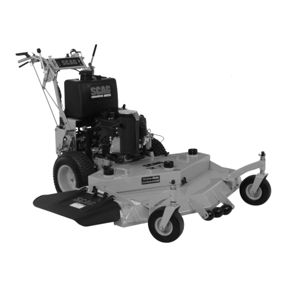
OPERATOR'S
MANUAL
SWZ
Walk-Behind
Model:
SWZ36A-481FS
SWZ48V-541FS
SWZ52V-600FS
SWZ-600FS
SWZ-651FSE
PART NO. 03320
PRINTED 9/2012
PRINTED IN USA
Advertisement
Table of Contents

Related Manuals for Scag Power Equipment SWZ36A-481FS


Summary of Contents for Scag Power Equipment SWZ36A-481FS
- Page 1 The specific models that this book covers are listed on the inside cover. Before operating your machine, please read all the information enclosed. © 2012 PART NO. 03320 Scag Power Equipment PRINTED 9/2012 Division of Metalcraft of Mayville, Inc. PRINTED IN USA...
- Page 2 CONCERN, PRUDENCE, AND PROPER TRAINING OF THE PERSONNEL INvOLvED IN THE OPERATION, TRANSPORT, MAINTENANCE, AND STORAGE OF THE EqUIPMENT. This manual covers the operating instructions and illustrated parts list for: SWz36A-481FS with a serial number of H2700001 to H2799999 SWz48v-541FS...
-
Page 3: Table Of Contents
Table of Contents Table of Contents SECTION 1 - GENERAL INFORMATION ...................1 1.1 INTRODUCTION ............................1 1.2 DIRECTION REFERENCE ...........................1 1.3 SERvICING THE ENGINE AND DRIvE TRAIN COMPONENTS ..............1 1.4 SYMBOLS ..............................2 SECTION 2 - SAFETY INFORMATION ..................3 2.1 INTRODUCTION ............................3 2.2 SIGNAL WORDS ............................3 2.3 BEFORE OPERATION CONSIDERATIONS ....................3 2.4 OPERATION CONSIDERATIONS ........................4... - Page 4 Table of Contents SECTION 6 - ADJUSTMENTS ....................18 6.1 PARkING BRAkE ADJUSTMENT ......................18 6.2 NEUTRAL ADJUSTMENT .........................18 6.3 STEERING CONTROL ROD ADJUSTMENTS ..................18 6.4 TRACkING ADJUSTMENT ........................19 6.5 THROTTLE CONTROL AND CHOkE ADJUSTMENTS ................19 6.6 CUTTER DECk BELT ADJUSTMENTS ....................19 6.7 BELT ALIGNMENT .............................20 6.8 ADJUSTING CUTTING HEIGHT ........................20 6.9 ELECTRIC CLUTCH ADJUSTMENT ......................23...
-
Page 5: General Information
Scag service parts. All information is based upon product information available - IMPORTANT - at the time of approval for printing. Scag Power Equipment The replacement of any part on this product reserves the right to make changes at any time without by other than the manufacturer's authorized notice and without incurring any obligation. -
Page 6: Symbols
Section 1 SYMBOLS SYMBOL DESCRIPTION SYMBOL DESCRIPTION Choke Transmission Parking Brake Spinning Blade 48071S On/Start Spring Tension on Idler Off/Stop Falling Hazard Thrown Object Hazard Fast Slow Continuously Variable - Linear Cutting Element - Basic Symbol Pinch Point Cutting Element - Engage 481039S Hour meter/Elapsed Operating Hours Cutting Element - Disengage... -
Page 7: Safety Information
Section 2 SAFETY INFORMATION INTRODUCTION DANGER Your mower is only as safe as the operator. Carelessness or operator error may result in serious bodily injury The signal word “DANGER” denotes that an extremely or death. Hazard control and accident prevention are hazardous situation exists on or near the machine that dependent upon the awareness, concern, prudence, and could result in high probability of death or irreparable injury... -
Page 8: Operation Considerations
Section 2 DO NOT allow children to ride or play on the Fuel is flammable; handle it with care. Fill the fuel machine, it is not a toy. tank outdoors. Never fill it indoors. Use a funnel or spout to prevent spillage. Clean up any spillage Clear the area to be mowed of objects that could be before starting the engine. - Page 9 Section 2 Start the engine when the neutral latches are in CAUTION the neutral lock position, the cutter blades are disengaged, parking brake is engaged and the speed control lever is in neutral. Do not touch the engine or the muffler while the If the mower discharge ever plugs, shut off the engine is running or immediately after stopping.
-
Page 10: Maintenance Considerations & Storage
Section 2 MAINTENANCE CONSIDERATIONS & WARNING STORAGE Never make adjustments to the machine with the Hydraulic fluid is under high pressure and can engine running unless specifically instructed to do penetrate skin causing injury. If hydraulic fluid so. If the engine is running, keep hands, feet, and is injected into the skin, it must be surgically clothing away from moving parts. -
Page 11: Safety And Instructional Decals
Section 2 SAFETY AND INSTRUCTIONAL DECALS... -
Page 12: Specifications
General Type ....................Heavy Duty Industrial/Commercial Gasoline Brand ..................................Kawasaki Engine Model: (Scag Model SWZ36A-481FS) ..................Kawasaki Model # FS481V (Scag Model SWZ48V-541FS) ..................Kawasaki Model # FS541V (Scag Model SWZ52V-600FS, SWZ-600FS) ..............Kawasaki Model # FS600V (Scag Model SWZ-651FSE) ....................Kawasaki Model # FS651V Displacement: Kawasaki FS481V .............................. -
Page 13: Cutter Deck
Section 3 CUTTER DECk Type ........................Out-Front design with anti-scalp rollers Construction ....36 / 48 = 7-Gauge Deck Top w/10-Gauge Reinforced Spindle Area, 7-gauge (3/16") Deck Skirt 52 / 61 = 10-Gauge Deck Top w/10-Gauge Reinforced Spindle Area, 7-Gauge (3/16") Deck Skirt True Cutting Width: 36 .................................35.5"... -
Page 14: Operating Instructions
Section 4 OPERATING INSTRUCTIONS Mower Deck Switch (Figure 4-1). Used to engage CAUTION and disengage the mower drive system. Pulling up on the switch will engage the deck drive. Pushing down on the switch will disengage the deck drive. Do not attempt to operate this mower unless you Engine Choke Control (Figure 4-1). -
Page 15: Safety Interlock System
Section 4 STARTING THE ENGINE Speed Control Lever (Figure 4-1). Used to select the forward speed. Neutral Latch (Figure 4-1). Used to secure the CAUTION hydraulic drive system in neutral. Apply neutral latches when parking the machine. Operator Pressence Control (Figure 4-1) DO NOT USE STARTING FLUIDS. -
Page 16: Engaging The Deck Drive (Cutter Blades)
Section 4 FORWARD TRAvEL - NOTE - The mower may not travel straight in reverse. To travel forward with the mower, release the parking brake, select the desired speed using the speed control lever, pull To steer left while traveling in reverse, pull upward on the steering control levers upward, release the neutral latch right steering control lever. -
Page 17: Hillside Operation
Section 4 Keep the entire mower clean to inhibit serious heat HILLSIDE OPERATION damage to the engine or hydraulic oil circuit. Check the drive belts for proper alignment and any WARNING signs of wear. Correct and adjust if necessary. DANGER DO NOT operate on steep slopes. -
Page 18: Moving Mower With Engine Stopped
Section 4 4.11 MOvING MOWER WITH ENGINE Cut grass when it is dry and not too tall. Do not cut grass too short (cut off 1/3 or less of existing grass STOPPED for best appearance). Mow frequently. Keep mower and discharge chute clean. To “free-wheel”... -
Page 19: Troubleshooting Cutting Conditions
Section 5 TROUBLESHOOTING CUTTING CONDITIONS CONDITION CAUSE CURE STRINGERS - OCCASIONAL Low engine RPM Run engine at full RPM BLADES OF UNCUT GRASS Ground speed too fast Slow speed to adjust for conditions Wet grass Cut grass after it has dried out Dull blades, incorrect sharpening Sharpen blades Deck plugged, grass accumulation... - Page 20 Section 5 TROUBLESHOOTING CUTTING CONDITIONS (CONT'D) CONDITION CAUSE CURE U N E v E N C U T O N F L AT Lift worn from blade Replace blade GROUND - WAvY HIGH-LOW APPEARANCE, SCALLOPED Blade upside down Mount with cutting edge toward ground CUT, OR ROUGH CONTOUR Deck plugged, grass accumulation Clean underside of deck...
- Page 21 Section 5 TROUBLESHOOTING CUTTING CONDITIONS (CONT'D) CONDITION CAUSE CURE SCALPING - BLADES HITTING Low tire pressures Check and adjust pressures DIRT OR CUTTING vERY CLOSE TO THE GROUND Ground speed too fast Slow speed to adjust for conditions May need to reduce ground speed, raise Cutting too low cutting height, change direction of cut, and/or change pitch and level...
-
Page 22: Adjustments
Section 6 ADJUSTMENTS PARkING BRAkE ADJUSTMENT Adjust the parking brake so that when the brake hand lever is against the stop on the handle bar, the brake levers on the brake shaft weldment are against the stops on the engine deck. CAUTION Figure 6-1. -
Page 23: Tracking Adjustment
Section 6 TRACkING ADJUSTMENT -NOTE- Before proceeding with this adjustment, be sure that the tire pressures are correct and the neutral adjustment and the steering control rod adjustment have been completed. Figure 6-3. Tracking Adjustment With the machine on a flat level surface, start the engine, release the parking brake and place the THROTTLE CONTROL AND CHOkE speed control lever into the speed that will most... -
Page 24: Belt Alignment
Section 6 -NOTE- Due to many cutting conditions that exist, it is difficult to suggest a cutter deck setting that will work for every lawn. Due to initial belt stretch and to prevent the belt There are two adjustments that can be made to the cutter from slipping, check this adjustment after the first deck, pitch and height. - Page 25 Section 6 CUSTOM-CUT BAFFLE ADJUSTMENT BLADE HEIGHT ADJUSTMENT The Custom-Cut Baffle is designed to deliver optimum Adjusting the blade height can be done by moving any number airflow and superior cutting performance in any type of of the five smaller 1/4" spacers on the blade mounting bolts grass.
- Page 26 Section 6 Custom-Cut Baffle Adjustment Mounting Slot Selected Mounting Hardware Location Slot “A” Hole 1 Hole 2 Hole 3 Hole 4 Height (inches) 3-3/4” 4-1/4” 4-3/4” 5-1/4” Slot “B” Hole 2 Hole 3 Hole 4 Height (inches) 3-1/2” 4” 4-1/2” Figure 6-10.
-
Page 27: Electric Clutch Adjustment
Section 6 ELECTRIC CLUTCH ADJUSTMENT ADJUSTMENT NUTS The electric clutch serves two functions in the operation of the mower. In addition to starting and stopping the power flow to the cutter blades, the clutch also acts as a brake to assist in stopping blade rotation when the PTO is switched off or the operator presence circuit is interrupted. -
Page 28: Maintenance
Section 7 MAINTENANCE MAINTENANCE CHART - RECOMMENDED SERvICE INTERvALS HOURS PROCEDURE COMMENTS BREAk-IN 100 200 500 (FIRST 10) Check all hardware for tightness C h e c k a l l b e l t s f o r p r o p e r See paragraph 7.6 alignment Check all hydraulic fittings and... -
Page 29: Lubrication
Section 7 MAINTENANCE CHART - RECOMMENDED SERvICE INTERvALS (CONT'D) HOURS PROCEDURE COMMENTS BREAk-IN (FIRST 10) Check hardware for tightness Change engine oil filter See paragraph 7.4 Replace engine fuel filter See paragraph 7.5 Grease caster wheel pivot See paragraph 7.2 shafts Drain hydraulic system and See paragraph 7.3... - Page 30 Section 7 GREASE FITTING LUBRICATION LUBRICANT / INTERVAL LITHIUM MP WHITE GREASE 2125 ( 40 HOURS / WEEKLY ) CHASSIS GREASE ( 100 HOURS / BI-MONTHLY ) CHASSIS GREASE ( 200 HOURS / MONTHLY ) 390S0177 Figure 7-1. Lubrication Fitting Points...
-
Page 31: Hydraulic System
Section 7 HYDRAULIC SYSTEM A. CHECkING HYDRAULIC OIL LEvEL The hydraulic oil level should be checked after the first 8 Filter Head Hydraulic Oil hours of operation. Thereafter, check the oil after every Drain Cap 200 hours of machine operation or monthly, whichever occurs first. -
Page 32: Engine Oil
Section 7 ENGINE OIL FILLER NECK INSERT A. CHECkING ENGINE CRANkCASE OIL LEvEL FUEL LEVEL The engine oil level should be checked after every 8 hours of operation or daily as instructed in the Engine Operator’s Manual furnished with this mower. B. -
Page 33: Engine Air Cleaner
Section 7 BATTERY - ELECTRIC START MODELS Replace gas cap and tighten securely. For Low Emission (LE) and EPA Phase 3 (produced after 1/1/2011) models, tighten the fuel cap until it ratchets. WARNING B. REPLACING IN-LINE FUEL FILTER ELEMENTS Lead-acid batteries produce flammable and explosive gases. -
Page 34: Cutter Blades
Section 7 A. CHARGING THE BATTERY CUTTER BLADES Refer to the battery charger’s manual for specific A. BLADE INSPECTION instructions. Remove the ignition key before servicing the blades. Under normal conditions the engine’s alternator will have no problem keeping a charge on the battery. If the battery WARNING has been completely discharged for a long period of time, the alternator may not be able to recharge the battery, and... -
Page 35: Tires
Section 7 - NOTE - CAUTION DO NOT sharpen the blades beyond 1/3 of the width of the blade. See Figure 7-4. Inspect the cutter blade spacer(s) and washer Sharpen the cutting edge at the same bevel as the for wear and/or cupping. Replace the worn parts. original. -
Page 36: Illustrated Parts List
Section 8 ILLUSTRATED PARTS LIST SCAG APPROvED ATTACHMENTS AND ACCESSORIES. Attachments and accessories manufactured by companies other than Scag Power Equipment are not approved for use on this machine. Scag approved attachments and accessories: • Mulch Plate (p/n 9258, 9286, 9287, 9288) •... -
Page 37: Caster Assembly
Section 8 CASTER ASSEMBLY SW-SWZ2006CSTR Ref. Part No. Description 04066-01 Quick Pin 43037-01 Spacer, Spacer Yoke, 1/2" Long 48100-01 Bronze Bearing 48114-04 Greasing Fitting 46082 Support Assembly (Incl. #3 & #4) 45006 Caster Yoke 04021-07 Nut, Elastic Stop 1/2-13 43022 Sleeve, Caster Wheel Bearing 04001-37 Bolt, Hex Head 1/2-13 x 5-1/2"... -
Page 38: 36A Cutter Deck
Section 8 36A CUTTER DECk SW2011CD36A... - Page 39 Section 8 36A CUTTER DECk Ref. Ref. Part No. Description Part No. Description 04117-04 Nut, 1/2-13 Flange Elastic Stop 461848 Cutter Deck w/Decals 461663 Cutter Spindle Assembly 43277 Spacer, J-Hook 04041-12 Flatwasher, 3/8 x 1-1/2 x 16 GA 43312 Spacer, Outside 04021-09 Elastic Stop Nut, 3/8-16 481022...
-
Page 40: 48V & 52V Cutter Decks
Section 8 48v & 52v CUTTER DECkS 40 39 SW-06CD48V-52V... - Page 41 Section 8 48v & 52v CUTTER DECkS Ref. Ref. Part No. Description Part No. Description 44078 J-Hook, 48V 461852 Cutter Deck w/Decals 43028 J-Hook, 52V 461855 Cutter Deck w/Decals 48181 Idler Pulley, “V” Groove 461663 Spindle Assembly 04040-04 Flatwasher, 5/16" 43296 Spacer, Inside 482744...
-
Page 42: 61V Cutter Deck
Section 8 61v CUTTER DECk 40 39 SW-06CD48V-52V... - Page 43 Section 8 61v CUTTER DECk Ref. Ref. Part No. Description Part No. Description 461091 Idler Arm Assy. (Incl. 62) 461860 Cutter Deck w/Decals 483176 Pad, Deck Wear 461663 Spindle Assembly 43028 J-Rod, Idler Pulley 43296 Spacer, Inside 482745 Pulley 43077 Spacer, J-Rod 04041-12 Washer, 3/8 x 1-1/2 x 16 ga.
-
Page 44: Engine Deck - Manual Start
Section 8 ENGINE DECk - MANUAL START ENGINE DECk - MANUAL START SWZ 2013 EDMAN... - Page 45 Section 8 ENGINE DECk - MANUAL START Ref. Part No. Description 484408 Engine, Kawasaki FS481V 484409 Engine, Kawasaki FS541V 484410 Engine, Kawasaki FS600V 424620 Plate, Clutch Bracket 421370 Clutch Bracket 48030-09 Clamp 04003-04 Bolt, Carriage 5/16-18 x 1" 04021-10 Nut, 5/16-18 Elastic Stop 45418 Pulley Guard, 16"...
-
Page 46: Engine Deck - Electric Start
Section 8 ENGINE DECk - ELECTRIC START SWZ 2013 EDELCT... - Page 47 Section 8 ENGINE DECk - ELECTRIC START Ref. Part No. Description 484411 Engine, Kawasaki FS651V 424620 Plate, Clutch Bracket 04030-04 Lock Washer 3/8" 04001-32 Bolt, Hex Head 3/8-16 x 1-1/4" 424730 Heatshield, 20" Large Frame 04003-12 Carriage Bolt, 5/16-18 x .75" 48126 Rubber Boot 423308...
-
Page 48: Drive And Brake Components
Section 8 DRIvE AND BRAkE COMPONENTS DRIvE AND BRAkE COMPONENTS 3, 3A 10, 10A 37 41 SWZ05D&BC... - Page 49 Section 8 DRIvE AND BRAkE COMPONENTS Ref. Part No. Description 481876 Ring, Split 04001-19 Bolt, 3/8-16 x 1" Hex Head 45842 Brake Shaft Assembly Weldment, 16" Small Frame 45854 Brake Shaft Assembly Weldment, 20" Large Frame 04062-01 Hair Pin Cotter, .094 x 1.62 04003-12 Carrage Bolt, 5/16-18 x .75"...
-
Page 50: Handle Assembly - 16" Small Frame
Section 8 HANDLE ASSEMBLY - 16" SMALL FRAME 45 11 SWZ08SFHAN... - Page 51 Section 8 HANDLE ASSEMBLY - 16" SMALL FRAME Ref. Ref. Part No. Description Part No. Description 04063-07 Key, Woodruff, 3/16 x .75 461976 Upper Handle Wlmt. W/Decals 04001-59 Bolt, Hex Head, 1/4-20 x 1.25" 42675 Quadrant, Speed Control 04001-19 Bolt, Hex Head, 3/8-16 x 1" 04062-02 Hairpin, .094 x 1.19 45282...
- Page 52 Section 8 HANDLE ASSEMBLY - 20" LARGE FRAME 45 11 SWZ 08 LFHAN...
-
Page 53: Handle Assembly - 20" Large Frame
Section 8 HANDLE ASSEMBLY - 20" LARGE FRAME Ref. Ref. Part No. Description Part No. Description 04063-07 Key, Woodruff, 3/16 x .75 461977 Upper Handle Wlmt. W/Decals 04001-59 Bolt, Hex Head, 1/4-20 x 1.25" 42675 Quadrant, Speed Control 04001-19 Bolt, Hex Head, 3/8-16 x 1" 04062-02 Hairpin, .094 x 1.19 43415... -
Page 54: Swz Fuel System
Section 8 SWz FUEL SYSTEM FUEL SYSTEM - EPA PHASE 3 (produced after 1/1/2010) Tank Purge To Fuel Pump To Engine Purge Port 2011 SWZ EPA Phase 3 Fuel System... - Page 55 Section 8 SWz FUEL SYSTEM Ref. Part No. Description 462375 Fuel Tank Assembly (incl. #3, 4, 5, 6, 16, 17) 484286 Fuel Cap w/ Tether 484297 Fuel Cap w/Tethered - California Models Only (not shown) 484259 Fuel Gauge Assembly (incl. #4) 484242 Seal, Fuel Gauge 482571...
-
Page 56: Hydraulic Assembly
Section 8 HYDRAULIC ASSEMBLY HYDRAULIC ASSEMBLY 2005SWZ-HA... - Page 57 Section 8 HYDRAULIC ASSEMBLY Ref. Part No. Description 481164 Cap, Oil Reservoir 461428 Oil Reservoir (With Fittings) 482266-01 Elbow, 9/16 O-Ring x 3/8" Hose 48811 Hose, 3/8" ID - 10-1/4" Long (Order By The Inch) 48811 Hose, 3/8" ID - 7" Long (Order By The Inch) 48603-06 O-Ring 483097...
-
Page 58: Hydraulic Pump Assembly
Section 8 HYDRAULIC PUMP ASSEMBLY PORT "A" SIDE PORT "B" SIDE... - Page 59 Section 8 HYDRAULIC PUMP ASSEMBLY Ref. Part No. Description HG 70516 Housing Kit HG 70573 End Cap Kit HG 50641 Straight Headless Pin HG 50969 Hex Flange Bolt, M8-1.25 x 60mm HG 51232 Housing O-Ring HG 2513027 Charge Pump Kit HG 50273 Gerotor Assembly HG 9004101-1340...
-
Page 60: Wire Harnesses
Section 8 WIRE HARNESSES CLUTCH ENGINE DECK WIRE HARNESS NEUTRAL INTERLOCK PART NO. 484302 DIODE (600V 6A) GROUND BLACK W/RED STRIPE BLACK BLUE BLACK BLUE MAGNETO INSTRUMENT RECTIFIER WHITE PANEL HARNESS WHITE YELLOW HANDLE WIRE HARNESS - MANUAL START PART NO. 482686 SWZ2003WH482686... - Page 61 Section 8 WIRE HARNESSES NEUTRAL INTERLOCK ENGINE DECK WIRE HARNESS GROUND ELECTRIC START PART NO. 484283 BLACK W/RED STRIPE GREEN BLACK BLACK BLUE BLUE CLUTCH INSTRUMENT WHITE PANEL HARNESS WHITE YELLOW RED W/YEL STRIPE DIODE (600V 6A) STARTER SOLENOID HANDLE WIRING HARNESS kAWASAkI ELECTRIC START PART NO.
-
Page 62: Replacement Decals And Information Plates
Section 8 REPLACEMENT DECALS AND INFORMATION PLATES WARNING DO NOT OPERATE WITHOUT DISCHARGE CHUTE, MULCHING kIT, OR ENTIRE GRASS CATCHER INSTALLED 483405 WARNING ROTATING BLADES AND BELTS SPINNING BLADES * keep hands, feet & clothing clear * keep all guards in place kEEP CLEAR * Shut off engine &... - Page 63 Section 8 REPLACEMENT DECALS AND INFORMATION PLATES 481423 FAST SPEED CONTROL SLOW NEUTRAL 482297 481124 Hea vy- Duty Comm e rcial 481971...
- Page 64 Section 8 REPLACEMENT DECALS AND INFORMATION PLATES Ref. Part No. Description 483405 Decal, Discharge Chute 48314 Decal, Scag Logo 483407 Decal, Danger-Spinning Blades 483406 Decal, Warning-Rotating Blades 482816 Decal, Height of Cut 48404 Decal, Metalcraft - Made in USA 483441 Decal, Instrument Panel - Rear 483404 Decal, Sulky Attachment...
- Page 65 Section 8...
-
Page 66: Limited Warranty - Commercial Equipment
Cutter decks are warranted against cracking for a period of three (3) years. (parts and labor 1st and 2nd year; parts only 3rd year.) The repair or replacement of the cutter deck will be at the option of Scag Power Equipment. We reserve the right to request compo- nents for evaluation. - Page 67 © 2012 Scag Power Equipment Division of Metalcraft of Mayville, Inc.