Table of Contents
Advertisement
CHAPTER 1
Chapter 1
INTRODUCTION
The MS-6188 Flex ATX WH11 mainboard is a high-performance
computer mainboard based on Intel
®
for the Intel
Celeron
business/personal desktop markets.
The Intel
chipset for the Intel
tecture consists of dedicated multi-media engines executing in parallel to
deliver high performance 3D, 2D, and motion compensation video capabili-
ties. An integrated centralized memory arbiter allocates memory bandwidth
to multiple system agents to optimize system memory utilization. A new
chipset component interconnect, the hub interface, is designed into the Intel
810 chipset to provide an efficient communication channel between the
memory controller hub and I/O hub controller.
The Intel 810 chipset contains three core components: the Graph-
ics and Memory Controller Hub (GMCH), the I/O Controller Hub (ICH) and
the Firmware Hub (FWH). The GMCH integrates a 66/100MHz, P6 family
system bus controller, integrates 2D/3D graphics accelerator, 100MHz
SDRAM controller and high-speed hub interface for communication with the
ICH. The ICH integrates an Ultra ATA66(ICH) controller, USB host control-
ler, LPC interface controller, FWH inteface conroller, PCI interface controller,
AC'97 digital controller and a hub interface for communication with the
GMCH.
®
TM
/ Coppermine (PPGA) processor for inexpensive
®
810 chipset is the first generation Integrated Graphics
®
TM
Celeron
processor. The graphics accelerator archi-
810 chipset. The MS-6188 is designed
1-1
INTRODUCTION
Advertisement
Table of Contents

Related Manuals for MSI MS-6188


Summary of Contents for MSI MS-6188
- Page 1 CHAPTER 1 INTRODUCTION Chapter 1 INTRODUCTION The MS-6188 Flex ATX WH11 mainboard is a high-performance ® computer mainboard based on Intel 810 chipset. The MS-6188 is designed ® for the Intel Celeron / Coppermine (PPGA) processor for inexpensive business/personal desktop markets.
-
Page 2: Mainboard Features
CHAPTER 1 INTRODUCTION 1.1 Mainboard Features l Support Socket370 for Intel ® Celeron /Coppermine processor. l Support 300MHz, 333MHz, 366MHz, 400MHz, 433MHz, 466MHz or higher Chipset l Intel ® 810 (GMCH) chipset. (421 BGA) - Integrated Graphics Controller - Intel DDM+ Architecture - SDRAM memory Independent of System Bus l Intel ®... - Page 3 CHAPTER 1 INTRODUCTION On-Board Peripherals l On-Board Peripherals include: - 1 floppy port supports 2 FDD with 360K, 720K, 1.2M, 1.44M and 2.88Mbytes. - 2 serial port (1 rear port + 1 header) - 1 parallel port supports SPP/EPP/ECP mode - 4 USB ports(2 USB rear ports + 2 USB front headers) - 1 IrDA connector for SIR.
- Page 4 CHAPTER 1 INTRODUCTION Dimension l Flex ATX Form Factor: 7.5” x 9” inches Mounting l 6 mounting holes. Warning: According to Intel 810 chipset specification: 810E chipset sup- ports 66/100/133 MHz FSB processor and 810/810DC100 chipset supports 66/ 100 FSB processor. Please do not use 133MHz FSB processor on motherboards which use 810/810DC100 chipset.
-
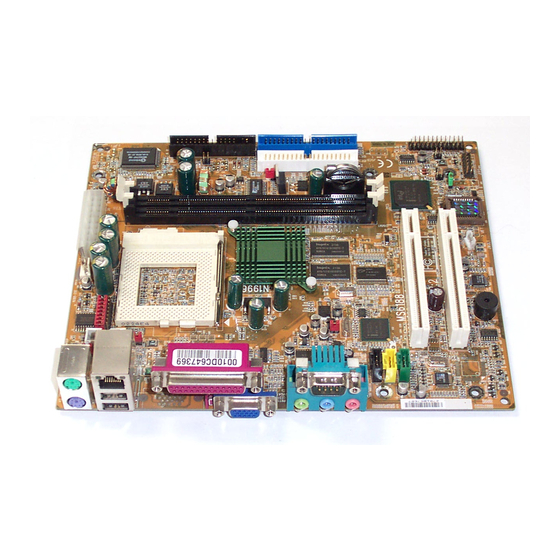
Page 5: Mainboard Layout
VGA Port Intel GMCH chipset (810) Top: COM A Bottom: Line-Out Line-In SDRAM SDRAM Intel CD_IN 82559 AUX_IN Chipset MODEM_IN PCI SLOT 1 CODEC JIR1 PCI SLOT 2 JGS1 JMDM1 JBIOS JBAT JUSB1 JWOL1 JFP2 MS-6188 Flex ATX WH11 Mainboard... -
Page 6: Hardware Installation
Chapter 2 HARDWARE INSTALLATION 2.1 Central Processing Unit: CPU ® The mainboard operates with Intel Coppermine(FC-PGA) or Celeron processor. The mainboard uses a CPU socket called Socket 370 for easy CPU installation. The CPU should always have a Heat Sink and a cooling fan attached to prevent overheating. -
Page 7: Cpu Core Speed Derivation Procedure
2.1-2 CPU Core Speed Derivation Procedure The mainboard CPU Bus Frequency can be set through BIOS setup CPU Clock 66MHz Core/Bus ratio then CPU core speed Host Clock x Core/Bus ratio 66MHz x 3.5 233MHz... -
Page 8: Fan Power Connector: Cpufan
2.1-3 Fan Power Connector: CPUFAN This connector support system cooling fan with + 12V. It supports three pin head connector. When connecting the wire to the connector, always take note that the red wire is the positive and should be connected to the +12V, the black wire is Ground and should be connected to GND. - Page 9 A battery must be used to retain the mainboard configuration in CMOS RAM. Short 1-2 pins of JBAT to store the CMOS data. JBAT Clear Data Keep Data Note: You can clear CMOS by shorting 2-3 pin, while the system is off. Then, return to 1-2 pin position.
-
Page 10: Memory Bank Configuration
2.3-1 Memory Bank Configuration The mainboard supports a maximum memory size of 256MB(64-bit technol- ogy) or 512MB(128-bit technology for SDRAM: It provides two 168-pin unbuffered DIMMs (Double In-Line Memory Module) sockets. It supports 8 MB to 128 Mbytes DIMM memory module. -
Page 11: Memory Installation Procedures
2.3-2 Memory Installation Procedures A. How to install a DIMM Module Single Sided DIMM Double Sided DIMM 1. The DIMM slot has 2 Notch Keys “VOLT and DRAM”, so the DIMM memory module can only fit in one direction. 2. Insert the DIMM memory module vertically into the DIMM slot. Then push it in. -
Page 12: Memory Population Rules
2.3-3 Memory Population Rules 1. Supports only SDRAM DIMM. 2. To operate properly, at least one 168-pin DIMM module must be in- stalled. 3. This mainboard supports Table Free memory, so memory can be installed on DIMM1 or DIMM 2 in any order. 4. -
Page 13: Case Connector: Jfp2
2.4 Case Connector: JFP2 The Power Switch, Reset Switch, Power LED, Speaker, and HDD LED are all connected to the JFP2 connector block. Speaker Reset Switch JFP2 Dual Color Power Switch Power LED Single Color... -
Page 14: Power Switch
2.4-1 Power Switch Connect to a 2-pin push button switch. This switch has the same feature with JRMS1. 2.4-2 Reset Switch Reset switch is used to reboot the system rather than turning the power ON/ OFF. Avoid rebooting while the HDD LED is lit. You can connect the Reset switch from the system case to this pin. -
Page 15: Floppy Disk Connector: Fdd1
2.5 Floppy Disk Connector: FDD1 The mainboard also provides a standard floppy disk connector FDD1 that supports 360K, 720K, 1.2M, 1.44M and 2.88M floppy disk types. This connector supports the provided floppy drive ribbon cables. FDD1 2-10... -
Page 16: Hard Disk Connectors: Ide1 & Ide2
2.6 Hard Disk Connectors: IDE1 & IDE2 The mainboard has a 32-bit Enhanced PCI IDE and Ultra DMA/66 (ICH)/ Ultra DMA/33(ICH0) Controller that provides PIO mode 0~4, Bus Master, and Ultra DMA/33 function. It has two HDD connectors IDE1 (primary) and IDE2 (secondary). -
Page 17: Atx 20-Pin Power Connector: Jwr1
2.7-1 ATX 20-pin Power Connector: JWR1 This connector supports the power button on-board. Using the ATX power supply, functions such as Modem Ring Wake-Up and Soft Power Off are supported by this mainboard. This power connector supports instant power on function which means that system will boot up instantly when the power connector is inserted on the board. -
Page 18: Irda Infrared Module Connector: Jir1
2.8 IrDA Infrared Module Connector: JIR1 The mainboard provides one infrared (JIR1) connector for IR modules. This connector is for optional wireless transmitting and receiving infrared module. You must configure the setting through the BIOS setup to use the IR function. - Page 19 The mainboard has a 9-pin male DIN connector for serial port COM A. This port is a 16550A high speed communication port that send/receive 16 bytes FIFOs. You can attach a mouse or a modem cable directly into this connec- tor.
- Page 20 The mainboard provides a 25 pin female centronic connector for LPT. A parallel port is a standard printer port that also supports Enhanced Parallel Port(EPP) and Extended capabilities Parallel Port(ECP). See connector and pin definition below: Parallel Port (25-pin Female) LPT 1 PIN DEFINITION SIGNAL...
-
Page 21: Vga Db 15 Pin Connector
2.11 VGA DB 15 Pin Connector The mainboard provides a DB 15-pin connector to connect to a VGA monitor. Analog Video Display Connector(DB15-S) Signal Description Green Blue Not used Ground Ground Ground Ground Not used Ground Not used Horizontal Sync Vertical Sync 2-16... -
Page 22: Keyboard Connector: Jkbms1
® The mainboard provides a standard PS/2 mouse mini DIN connector for ® ® attaching a PS/2 mouse. You can plug a PS/2 mouse directly into this connector. The connector location and pin definition are shown below: Pin5 Mouse Clock Pin6 Pin3 Pin4... -
Page 23: Audio Port Connectors
2.14 DFP Connector (optional) The mainboard provides a 20-pin connector for DFP(Digital Flat Panel) Monitors. 2.15 Audio Port Connectors Line Out is a connector for Speakers or Headphones. Line In is used for external CD player, Tape layer, or other audio devices. Mic is a connector for the microphones. -
Page 24: Usb Connectors
2.16 USB Connectors The mainboard provides a UHCI(Universal Host Controller Interface) Universal Serial Bus root for attaching USB devices like: keyboard, mouse and other USB devices. You can plug the USB device directly to this connector. USB Port 2 1 2 3 4 USB Port 1 SIGNAL -Data... - Page 25 2.17 LAN Connector (optional, default setting) The mainboard provides a RJ-45 LAN connector for your Network need. RJ-45 LAN Port 2-20...
- Page 26 Attach a power saving switch to JGS1. When the switch is pressed, the system immediately goes into suspend mode. Press any key and the system wakes up. JGS1 2-21...
- Page 27 The JWOL1 connector is for use with LAN add-on cards that supports Wake Up on LAN function. To use this function, you need to set the “Wake-Up on LAN” to enable at the BIOS Power Management Setup. JWOL1 SIGNAL 5VSB MP_WAKEUP Note: LAN wake-up signal is active “high”.
- Page 28 The JKBV1 jumper is for setting keyboard power. This function should be set in the BIOS for the keyboard Wake-up function. JKBV1 5V (default) 5V Standby Disable keyboard Enable keyboard power on function power on function Note: To be able to use this function, you need a power supply that provide enough power for this feature.
- Page 29 The JMDM1 connector is for used with Modem add-on card that supports the Modem Wake Up function. JMDM1 Note: To be able to use this function, you need a power supply that provide enough power for this feature. (Power supply with 750ma 5V Stand-by) 2-24...
- Page 30 2.22 Modem-In: J7 The connector is for Modem with internal voice connector. Mono_Out GND Phone_In Modem_In Mono_Out is connected to the Modem Speaker Out connector. Phone_In is connected to the Modem Microphone In connector. 2-25...
- Page 31 This connector is used for DVD Add on Card with Line In connector. R GND L AUX_IN 2-26...
- Page 32 This connector is for CD-ROM audio connector. CD_In 2-27...
- Page 33 This connector is connected to a 2-pin connector chassis switch. If the Chassis is open, the switch will be open. The system will record this status. To clear the warning, you must enter the BIOS settting and clear the status. NOTE: 1.
- Page 34 This jumper is used to locked/unlocked BIOS Flash. This Jumper should be unlock when flashing/programming the BIOS. JBIOS BIOS Flash BIOS Flash Locked Unlocked 2-29...
- Page 35 This jumper is used to Enabled/Disabled the onboard LAN power 3VSB Enabled Disabled 2-30...
- Page 36 This jumper is used to Enabled/Disabled the DIMM power 3VSB. If your OS uses S3 function, short this jumper. Enabled Disabled NOTE: 6188M doesn’t support S3 function. 2-31...
- Page 37 The mainboard provides a front Universal Serial Bus connector. This is an optional USB connector for Front Panel. JUSB1 Description Description USBD2+ USBD3- USBD2- USBD3+ 2-32...
- Page 38 The mainboard provides a Front Panel Audio connector. This is an optional Audio connector for Front Panel. MIC_In Line_in R Line_in L Line_Out L Line_Out R 2-33...
- Page 39 This jumper is used for setting the rear port power. JUSBV1 5V (default) 5V Standby Note: If your OS supports S3 function and you use USB device. The JUSBV1 must be set on 1-2 and the USB device must be inserted on USB Port 1. Otherwise, the system will not be able to enter S3 mode.
- Page 40 The JP100 is use to support Coppermine CPU. JP100 Coppermine CPU Celeron CPU 2-35...
-
Page 41: Award Bios Setup
® Chapter 3 AWARD BIOS SETUP ® Award BIOS ROM has a built-in Setup program that allows users to modify the basic system configuration. This type of information is stored in battery-backed RAM (CMOS RAM), so that it retains the Setup information when the power is turned off. -
Page 42: Status Page Setup Menu/Option Page Setup Menu
® Power on the computer and press <Del> immediately to allow you to enter Setup. The other way to enter Setup is to power on the computer. When the below message appears briefly at the bottom of the screen during the POST (Power On Self Test), press <Del>... -
Page 43: Standard Cmos Setup
® ® Once you enter Award BIOS CMOS Setup Utility, the Main Menu (Figure 1) will appear on the screen. The Main Menu allows you to select from twelve setup functions and two exit choices. Use arrow keys to select among the items and press <Enter>... - Page 44 ® Advanced Chipset Features Use this menu to change the values in the chipset registers and optimize your system’s performance. Integrated Peripherals Use this menu to specify your settings for integrated peripherals. Power Management Setup Use this menu to specify your settings for power management. PnP/PCI Configuration This entry appears if your system supports PnP/PCI.
- Page 45 ® The items in Standard CMOS Setup Menu are divided into 10 catego- ries. Each category includes no, one or more than one setup items. Use the arrow keys to highlight the item and then use the <PgUp> or <PgDn> keys to select the value you want in each item.
- Page 46 ® Date The date format is <day><month> <date> <year>. Day of the week, from Sun to Sat, determined by BIOS. Read-only. month The month from Jan. through Dec. date The date from 1 to 31 can be keyed by numeric function keys.
- Page 47 ® If the controller of HDD interface is SCSI, the selection shall be “None”. If the controller of HDD interface is CD-ROM, the selection shall be “None”. Access Mode The settings are Auto, Normal, Large,LBA. Cylinder number of cylinders Head number of heads Precomp write precom...
-
Page 48: Anti-Virus Protection
® CMOS Setup Utility - Copyright(C) 1984-1999 Award Software Advanced BIOS Features Anti-Virus Protection Disabled CPU Internal Cache Enabled Item Help External Cache Enabled CPU L2 Cache ECC Checking Enabled Quick Power On Self Test Disabled Menu Level > First Boot device Floppy Second Boot device HDD-0... - Page 49 ® CPU Internal Cache The default value is Enabled. Enabled (default) Enable cache Disabled Disable cache Note: The internal cache is built in the processor. External Cache Choose Enabled or Disabled. This option enables the level 2 cache memory. CPU L2 Cache ECC Checking Choose Enabled or Disabled.
- Page 50 ® Boot Up NumLock Status The default value is On. On (default) Keypad is numeric keys. Keypad is arrow keys. Gate A20 Option Normal The A20 signal is controlled by keyboard controller or chipset hardware. Fast(default) The A20 signal is controlled by port 92 or chipset specific method.
- Page 51 ® OS Selection for DRAM > 64MB ® Allows OS2 to be used with > 64 MB of DRAM. Settings are Non- OS/2 (default) and OS2. Set to OS/2 if using more than 64MB and running ® OS/2 Report No FDD For Win 95 Whether report no FDD for Win 95 or not.
- Page 52 ® The Advanced Chipset Features Setup option is used to change the values of the chipset registers. These registers control most of the system options in the computer. Choose the “ADVANCED CHIPSET FEATURES” from the Main Menu and the following screen will appear. CMOS Setup Utility - Copyright(C) 1984-1999 Award Software Advanced Chipset Features SDRAM CAS Latency Time...
- Page 53 ® SDRAM CAS latency Time When synchronous DRAM is installed, the number of clock cycles of CAS latency depends on the DRAM timing. SDRAM Cycle Time Tras/Trc Select the number of SCLKs for an access cycle. The settings are: 5/7 and 6/8.
- Page 54 ® Video BIOS Cacheable Select Enabled allows caching of the video BIOS , resulting in better system performance. However, if any program writes to this memory area, a system error may result. The settings are: Enabled and Disabled. Memory Hole At 15M-16M You can reserve this area of system memory for ISA adapter ROM.
- Page 55 ® Initial Display Cache Enable and Disable Onboard Display Cache. The settings are: Enable and Disable. CAS# Latency The number of clock cycles of CAS# Latency depends on the Onboard Display cache timing. The settings are: 2 and 3. Paging Mode Control Select the paging mode control.
-
Page 56: Onchip Primary/Secondary Pci Ide
® CMOS Setup Utility - Copyright(C) 1984-1999 Award Software Integrated Peripherals OnChip Primary PCI IDE Enabled OnChip Secondary PCI IDE Enabled Item Help IDE Primary Master PIO Auto IDE Primary Slave PIO Auto IDE Secondary Master PIO Auto Menu Level >... - Page 57 ® IDE Primary/Secondary Master/Slave PIO The four IDE PIO (Programmed Input/Output) fields let you set a PIO mode (0-4) for each of the four IDE devices that the onboard IDE interface supports. Modes 0 through 4 provide successively increased performance. In Auto mode, the system automatically determines the best mode for each device.
- Page 58 ® IDE HDD Block Mode Block mode is also called block transfer, multiple commands, or multiple sector read/write. If your IDE hard drive supports block mode (most new drives do), select Enabled for automatic detection of the optimal number of block read/writes per sector the drive can support. The settings are: Enabled, Disabled.
-
Page 59: Onboard Parallel Mode
® Onboard Parallel Port Disabled There is a built-in parallel port on the (3BCH/IRQ7)/ on-board Super I/O chipset that pro- (278H/IRQ5)/ vides Standard, ECP, and EPP features. (378H/IRQ7) It has the following options: Disable 3BCH/IRQ7 Line Printer port 0 278H/IRQ5 Line Printer port 2 378H/IRQ7 Line Printer port 1... -
Page 60: Pwron After Pwr-Fail
® channels 3 or 1. The onboard parallel port is EPP Spec. compliant, so after the user chooses the onboard parallel port with the EPP function, the following message will be displayed on the screen: “EPP Mode Select.” At this time either EPP 1.7 spec. - Page 61 ® The Power Management Setup allows you to configure you system to most effectively save energy while operating in a manner consistent with your own style of computer use. CMOS Setup Utility - Copyright(C) 1984-1999 Award Software Power Management Setup IPCA Function Enabled ACPI Suspend Type...
-
Page 62: Acpi Suspend Type
® ACPI Suspend Type This item will set which ACPI suspend type will be used. S1 (POS) The S1 sleeping state is low wake-up latency sleeping state. In this state, no system context is lost(CPU or chip set) and hardware maintains all system context. -
Page 63: Soft-Off By Pwr-Bttn
® Video Off In Suspend This determines the manner in which the monitor is blanked. The settings are: Yes and No. Suspend Type Select the Suspend Type. The settings are: PWRON Suspend, Stop Grant. Modem Use IRQ This determines the IRQ in which the MODEM can use. The settings are: 3, 4, 5, 7, 9, 10, 11, NA. - Page 64 ® Power On by Ring During Disabled, the system will ignore any incoming call from the modem. During Enabled, the system will boot up if there’s an incoming call from the modem. Wake-Up on LAN To use this function, you need a LAN add-on card which support power on functions.
- Page 65 ® Reload Global Timer events are I/O events whose occurrence can prevent the system from entering a power saving mode or can awaken the system from such a mode. In effect, the system remains alert for anything which occurs to a device which is configured as Enabled , even when the system is in a power down mode.
-
Page 66: Reset Configuration Data
® This section describes configuring the PCI bus system. PCI, or Personal Computer Interconnect, is a system which allows I/O devices to operate at speeds nearing the speed the CPU itself uses when communicating with its own special components. This section covers some very technical items and it is strongly recommended that only experienced users should make any changes to the default settings. - Page 67 ® Resource Controlled By The Award Plug and Play BIOS has the capacity to automatically configure all of the boot and Plug and Play compatible devices. However, this capability means absolutely nothing unless you are using a Plug and ® Play operating system such as Windows 95/98.
-
Page 68: Cpu Warning Temperature
® This section shows the Status of you CPU, Fan, Warning for overall system status. CMOS Setup Utility - Copyright(C) 1984-1999 Award Software PC Health Status CPU Warning Temperature Disabled Current System Temp C/102 Item Help Current CPU Temperature C/150 Current System Fan 0RPM Current Power Fan... -
Page 69: Chassis Intrusion Detect
® Current System Temp/Current CPU Temperature/Current System Fan (optional)/Power Fan (optional)/Cpu Fan/Vcore/ VTT/3.3V/+5V/+12V/-12V/-5V/VBAT(V)/5VSB(V) This will show the CPU/FAN/System voltage chart and FAN Speed. Chassis Intrusion Detect Set this option to Enabled, Reset, or Disabled the chassis intrusion detector. During Enabled, any intrusion on the system chassis will be recorded. -
Page 70: Auto Detect Dimm/Pci Clk
® This section is for setting CPU Frequency/Voltage Control. CMOS Setup Utility - Copyright(C) 1984-1999 Award Software Frequency/Voltage Control Auto Detect DIMM/PCI Clk Enabled Spread Spectrum 0.50% (cntr) Item Help CPU Clock/Spread Spectrum Default CPU Ratio Auto Menu Level > ↑... - Page 71 ® Load Fail-Safe Defaults When you press <Enter> on this item, you get a confirmation dialog box with a message similar to: Load Fail-Safe Defaults (Y/N) ? N Pressing ‘Y’ loads the BIOS default values for the most stable, minimal- performance system operations.
- Page 72 ® You can set either supervisor or user password, or both of them. The differences are: Supervisor password : can enter and change the options of the setup menus. User password Can only enter but do not have the right to change the options of the setup menus.
- Page 73 ® You determine when the password is required within the BIOS Features Setup Menu and its Security option. If the Security option is set to “Sys- tem”, the password will be required both at boot and at entry to Setup. If set to “Setup”, prompting only occurs when trying to enter Setup.
-
Page 74: Intel 810 Integrated Graphics Controller
CHAPTER 4 VGA DRIVER Chapter 4 INTEL 810 INTEGRATED GRAPHICS CONTROLLER 1. Overview The Intel 810 Chipset extends Intel’s graphics capabilities into the value PC segment by incorporating 2D and 3D capabilities with the memory controller, to provide the industry with complete graphics offerings for every comput- ing segment. -
Page 75: System Requirements
CHAPTER 4 VGA DRIVER 1.2 System Requirements This section describes system requirements for the VGA Driver installa- tion and Usage. ® Computer Intel Celeron processor or higher Monitor VGA Support, mimimum 640x480 resolu- tion ® Operating system DOS 5.0 or higher, Windows 95/98, ®... -
Page 76: Intel 810 Vga Driver Setup & Usage Procedures
CHAPTER 4 VGA DRIVER 2. Intel 810 VGA Driver Setup & Usage Procedures Insert the CD-title into your CD-ROM drive. This CD will auto-run. This will display installation for VGA driver and sound driver, Intel 810/820 INF Update (only for Windows 95/98) and Trend PC-cillin 98. Just click the button for automatic installation for VGA driver. - Page 77 CHAPTER 4 VGA DRIVER ® 2.2 Windows NT 4.0 ® You need to install Windows NT “Service Pack 3” or higher, ® before you install Windows NT driver. 2.2-1 Display Driver Installation Procedure: Step 1: Click Start menu and select Control Panel from Settings group.
- Page 78 CHAPTER 4 VGA DRIVER 2.2-2 Changing resolution, color depth, and refresh rate: Step 1: Click Start menu and select Control Panel from Settings group. Step 2: Select Display icon. Step 3: Select Settings. Step 4: Select Color Palette to change between 256 color, 65536 colors, and 16777216 colors.
-
Page 79: Ich Audio Driver
CHAPTER 5 AUDIO DRIVER Chapter 5 ICH AUDIO DRIVER 1. Overview The ICH AC’ 97 digital controller provides the next generation of audio performance to the PC market. 1.1 Features PCI Bus Master for fast DMA. Fully Compliant with PC97 Power Management Specification. 1.2 System Requirements This section describes system requirements for the Audio Driver installation and Usage. -
Page 80: Audio Driver Setup & Usage Procedures
CHAPTER 5 AUDIO DRIVER 2. Audio Driver Setup & Usage Procedures Insert the CD-title into your CD-ROM drive. This CD will auto-run. This will display installation for VGA driver and sound driver, Intel 810/820 INF Update (only for Windows 95/98) and Trend PC-cillin 98. Just click the button for automatic installation for audio driver. - Page 81 CHAPTER 5 AUDIO DRIVER ® 2.2 Windows NT 4.0 2.2-1 Audio Driver Installation Procedure: Step 1: Insert the provided CD_ROM disk into the CD-ROM drive. Step 2: Look for the CD_ROM drive, double click on the CD_ROM icon. This will show the setup screen. Step 3: Click on “ADI SoundMax Drivers”...
- Page 82 ® Chapter 6 ® INTEL 82559 FAST ETHERNET LAN DRIVER The 82559 is a sophisticated 32-bit PCI component, with enhanced scatter- gather bus mastering capabilities. Its true 32-bit architecture enables it to perform high speed data transfers on the PCI bus using four DMA channels. 1.1 Features IEEE 802.3/802.3u 10BASE-T and 100BASE-TX compatible Glueless 32-bit PCI bus master interface...
- Page 83 ® ® 2.1 Windows 95/98 To install the driver, just insert the provided CD-ROM into the CD- ROM drive. The CD-ROM will autorun. Press the button for install- ing the LAN driver. 2.2 Other OS driver To install the driver for other operating system, just insert the provided CD-ROM into the CD-ROM drive.