Table of Contents
Advertisement
Advertisement
Table of Contents

Related Manuals for Lowrance Link-6S


Summary of Contents for Lowrance Link-6S
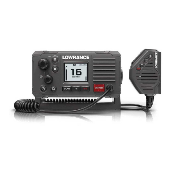
- Page 1 Link-6S Fixed Mount VHF User Guide ENGLISH lowrance.com...
- Page 2 In case of any queries, refer to the brand website of your unit or system: www.lowrance.com RF emissions statements European Union This Link-6S complies with CE under RED Directive 2014/53/EU. The relevant Declaration of conformity is available in the product’s section at the following website: www.navico.com Link-6S User Guide...
- Page 3 • Increase the separation between the equipment and receiver. • Connect the equipment into an outlet on a circuit different from that of the receiver is connected. • Consult the dealer or an experienced technician for help. Link-6S User Guide...
- Page 4 Le présent émetteur radio (Link-6S) a été approuvé par Industrie Canada pour fonctionner avec les types d’antenne énumérés ci- dessous et ayant un gain admissible maximal et l’impédance requise...
- Page 5 UK - United Kingdom GR - Greece NO - Norway Trademarks Lowrance® and Navico® are registered trademarks of Navico. NMEA® and NMEA 2000® are registered trademarks of the National Marine Electronics Association. Navico recommends that you check the radio operating licensing requirements of your country before using this VHF radio.
- Page 6 About this manual This manual is a reference guide for installing and operating a Link-6S VHF radio. Important text that requires special attention from the reader is emphasized as follows: ¼ Note: Used to draw the reader’s attention to a comment or some important information.
-
Page 7: Table Of Contents
DSC calls Track buddy Contacts My channels Shortcuts Installation Checklist Installation options Selecting a suitable mounting location First startup configuration Specifications Channel charts EU and INTERNATIONAL channel chart USA channel chart CANADA channel chart Dimensional drawings Contents | Link-6S User Guide... -
Page 8: General Information
General Information Your Link-6S provides the following useful features: • Prominent channel display • Built-in GPS receiver and antenna • With external GPS antenna connection • Adjustable contrast settings for the LCD • Adjustable keypad backlighting for easy night-time use •... -
Page 9: How To Display And Navigate Menus
To step backwards, press the MENU button. Press X to cancel entry and return to previous menu. LCD symbols and meanings When the Link-6S starts up it momentarily displays the brand, model, region, software version, and MMSI. General Information |... - Page 10 Weather channel bank active replaces channelbank icon temporarily (USA/CAN only) Channel is saved in the MY CHANNELS list Track your Buddy feature is active TRI watch or DUAL scan is active GPS simulator is active 10 | General Information | Link-6S User Guide...
- Page 11 Time (derived from GPS) - UTC offset is applied Latitude/Longitude Squelch level indicator Channel number (2 or 4 digits) The USA channel bank is active DSC functionality is enabled, but autoswitch is off Weather alert function is enabled | 11 General Information | Link-6S User Guide...
-
Page 12: Key Functions
Power / Backlight Short Press to adjust backlight level sequentally. Repeated short press of the power button will step through large backlight adjustments. The channel knob can be used to make finer 12 | General Information | Link-6S User Guide... - Page 13 ‘watched’ are the current channel the ‘watch’ channel, and the priority channel (the distress channel, CH16 for most countries). If the radio is set to ‘Country: USA’, two priority channels are watched - Channel 9 and Channel 16. | 13 General Information | Link-6S User Guide...
- Page 14 Holding either key will, after a short delay, step rapidly through the channels. PTT (handset mic only) Push-to-talk button. Press button to transmit. Only depress for duration of message to be broadcast. Radio can’t receive while it is transmitting. 14 | General Information | Link-6S User Guide...
-
Page 15: The Radio Menus
This menu is for choosing a scan mode to enable, as well as selection of the channels scanned per the MY CHANNELS list. ¼ Note: Scanning is not available if ATIS mode is turned on. All scan Scans all channels cyclically. | 15 The radio menus | Link-6S User Guide... -
Page 16: Watch
Select this to watch the current channel and the priority channel (Channel 16). TRI watch Select this to watch the current channel, the user selected ‘watch’ channel, and the priority channel (Channel 16). 16 | The radio menus | Link-6S User Guide... -
Page 17: Display
Range is OFF, then 1 to 10. Press MENU SELECT button to activate night mode (inverts display). Contrast Select to make adjustment of the screens contrast, using the channel knob. Range is 00 to 10. | 17 The radio menus | Link-6S User Guide... -
Page 18: Radio Setup
Volume can be set from 00 - 10 (where 00 is off, and 10 is loudest). Units Select SPEED to choose whether displayed in KNOTS, MPH, or KPH Select COURSE to toggle between displaying in MAGNETIC or TRUE. 18 | The radio menus | Link-6S User Guide... - Page 19 Select to toggle ON or OFF. When ON, NMEA 0183 data received is validated. If the checksum does not match, the data will be ignored. When OFF, there will be no tolerance to data corruption. | 19 The radio menus | Link-6S User Guide...
- Page 20 Select between NONE, 5 MINS, 10 MINS, and 15 MINS. (default is 10 MINS). ¼ Note: A different timeout is used when the radio is left in a DSC call. See “DSC timeout” on page 23 20 | The radio menus | Link-6S User Guide...
-
Page 21: Dsc Setup
DO NOT enter a random ‘made up’ number. ¼ Note: Contact a Lowrance dealer if you need to change your ATIS ID after initial input. Individual acknowledge (“INDIVIDUAL ACK”) The radio can be configured to automatically acknowledge an incoming ‘individual’... - Page 22 The radio can be configured to automatically acknowledge an incoming test call, or require manual intervention: MANUAL Operator must manually choose to send acknowledgement, or cancel. AUTO The DSC test call is automatically acknowledged after a 10 second delay. 22 | The radio menus | Link-6S User Guide...
-
Page 23: Alarms
WX alert (US/CAN only) The WX alert is a warning to the user that a special weather station alert has been received. It comprises of an audible alarm and visual alarm; | 23 The radio menus | Link-6S User Guide... -
Page 24: Reset
Reset Use this setting to return every setting to the factory defaults except all MMSI settings, entries in your buddy list and any customized channel names. 24 | The radio menus | Link-6S User Guide... -
Page 25: Dsc Call Menu
The nature of the distress call must be selected from the list of options - this will be displayed on other radios receiving the call. After the Distress Call is sent, the radio waits for an acknowledgment. | 25 DSC call menu | Link-6S User Guide... - Page 26 GCID, or by selecting a group from the RECENT list. When the SEND TO page is displayed, turn the channel knob to select the channel to use for voice communication. 26 | DSC call menu | Link-6S User Guide...
-
Page 27: Track Buddy
Up to 5 vessels from the Contacts list can be sent recurring position requests, at an adjustable time interval. The buddy list is saved permanently in memory, and tracking can be turned on and off as required. | 27 DSC call menu | Link-6S User Guide... -
Page 28: Contacts
The frequency that ‘buddys’ are polled with position requests can be adjusted, varying between 5 to 60 minutes. Contacts Used for the administation and calling of all individual Contacts as well as Groups. 28 | DSC call menu | Link-6S User Guide... - Page 29 ¼ Note: Adding a group to this list will in turn make the radio respond to a group call made from any other radio with the same group number in it’s memory. | 29 DSC call menu | Link-6S User Guide...
-
Page 30: My Channels
The available shortcut channels can be changed at any time using EDIT MY CHANNELS. ¼ Note: Channels on this list are also used in some SCAN options. Access to edit the MY CHANNELS list is also available from the SCAN menu. 30 | My channels | Link-6S User Guide... -
Page 31: Shortcuts
It’s purpose is solely for displaying radio information in one easy to access location. It provides detail on the MMSI number, GPS data status, and Vessel Callsign (if entered). Once the desired shortcuts have been selected, they are accessible directly from the Shortcuts page: | 31 Shortcuts | Link-6S User Guide... -
Page 32: Installation
Installation This Lowrance DSC VHF radio is designed to generate a digital maritime distress call to facilitate search and rescue. To be effective as a safety device, this radio must be used only within the geographic range of a shore-based VHF marine Channel 70 distress and safety watch system. -
Page 33: Installation Options
+/-20 deg from the front of the display. ¼ Note: If unsure, temporarily power up the radio and ensure the loca- tion is suitable. 20° 20° 20° 20° | 33 Installation | Link-6S User Guide... - Page 34 Insert the two mounting knobs through the holes and tighten them sufficiently to hold the radio at the desired viewing angle. Fit the mounting clips to the front of the radio to cover dash mount screw holes. 34 | Installation | Link-6S User Guide...
- Page 35 Use a 2.5 mm (3/32” ) drill bit to drill the 2 pilot holes. Using a Phillips screwdriver, secure the Mic mount using the supplied 3.5x20 mm selftapping screws to the mounting location. Hang the fist mic on the mount. | 35 Installation | Link-6S User Guide...
- Page 36 Install the gasket by firstly threading the attached cable through the centre of the gasket. • Screw the GPS antenna to the mounting surface. ¼ Note: Ensure the surface mounting area is clean with no dirt, old paint or debris. 36 | Installation | Link-6S User Guide...
- Page 37 (minimum) external speaker negative 3. NMEA 0183 RX_A (yellow): connect to TX_A of chart plotter, or active GPS antenna 4. NMEA 0183 RX_B (green): connect to TX_B of chart plotter, or active GPS antenna | 37 Installation | Link-6S User Guide...
-
Page 38: First Startup Configuration
¼ Note: MMSI entry can only be done once. Changing the MMSI requires radio be returned to a Lowrance dealer. For some EU region radios only: Enter the ATIS ID number. Re-enter 38 | Installation |... - Page 39 A Coast Station MMSI begins with 00 followed by 7 numeric digits (00xxxxxxx). • By law, you are not able to change your MMSI once it is entered into the radio. This is why there is the confirmation screen when entering the MMSI. | 39 Installation | Link-6S User Guide...
- Page 40 MMSI. • If you need to have the MMSI in the radio changed, the radio must be taken back to your Lowrance dealer. ATIS Automatic Transmitter Identification System (ATIS) is required for vessels making VHF transmissions whilst on the inland waterways of the Regional Arrangement Concerning the Radiotelephone Service on Inland Waterways (RAINWAT) signatory countries.
-
Page 41: Specifications
42 mm x 34 mm (1.65” x 1.3”), FSTN Contrast control: Backlight control: VHF antenna connector: SO-239 (50 ohm) GPS antenna connector: SMA (female) Waterproof: IPx7 Dimensions: W=166.7 mm (6.56”) x H=89.2 mm (3.5”) x D=161.4 mm (6.35”) - without bracket | 41 Specifications | Link-6S User Guide... - Page 42 2.6 ± 0.26 KHz DSC TX deviation at 2.1K: 4.2 ± 0.42 KHz ATIS TX deviation at 1.3 KHz: 1.3 ± 0.13 KHz ATIS TX deviation at 2.1 KHz: 2.1 ± 0.21 KHz 42 | Specifications | Link-6S User Guide...
- Page 43 Number of channels: 72 channels Horizontal accuracy: <10 m Position fixing time: Warm start: 30s, Cold start: 90s Position update interval: 1 second typical ¼ Note: Specifications are subject to change without notice. | 43 Specifications | Link-6S User Guide...
-
Page 44: Channel Charts
Recommendation ITU-R M.1084-5 Annex 4, Tables 1 and 3. The Table below also describes the harmonized channels where the digital technologies defined in the most recent version of Recommendation ITU-R M.1842 could be deployed. (WRC- 44 | Channel charts | Link-6S User Guide... - Page 45 160.625 TELEPHONE 156.075 160.675 PORT OPS 156.125 160.725 PORT OPS 156.175 160.775 PORT OPS 156.225 160.825 TELEPHONE 156.275 160.875 PORT OPS 156.325 160.925 PORT OPS 156.375 156.375 BRIDGE COM 156.425 156.425 SHIP-SHIP | 45 Channel charts | Link-6S User Guide...
- Page 46 Nos. 51.69, 51.73, 51.74, 51.75, 51.76, 51.77 and 51.78. However, the use of the channels which are shared with 46 | Channel charts | Link-6S User Guide...
- Page 47 (channels 10, 67, 73) may also be used, if so required, by the individual administrations concerned, for communication between ship stations, aircraft stations and participating land stations engaged in coordinated search and rescue and anti- | 47 Channel charts | Link-6S User Guide...
- Page 48 Additionally, AIS 1 and AIS 2 may be used by the mobile-satellite service (Earth-to-space) for the reception of AIS transmissions from ships. (WRC-07) q) When using these channels (10 and 11), all precautions should be taken to avoid harmful interference to channel70. (WRC-07) 48 | Channel charts | Link-6S User Guide...
- Page 49 Recommendation ITU-R M.2092, subject to coordination with affected administrations. (WRC-15) x) From 1 January 2017, in Angola, Botswana, Lesotho, Madagascar, Malawi, Mauritius, Mozambique, Namibia, Democratic Republic of the Congo, Seychelles, South Africa, Swaziland, Tanzania, Zambia | 49 Channel charts | Link-6S User Guide...
- Page 50 Article 5. From 1 January 2017, the frequency bands 157.025-157.100 MHz and 161.625-161.700 MHz (corresponding to channels: 80, 21, 81 and 22) are identified for utilization of the digital systems described 50 | Channel charts | Link-6S User Guide...
- Page 51 From 1 January 2019, channels 1027, 1028, 87 and 88 are used as single-frequency analogue channels for port operation and ship movement. (WRC-15) Source: ITU Radio Regulations (2016); reproduced with permission from ITU | 51 Channel charts | Link-6S User Guide...
-
Page 52: Usa Channel Chart
COMMERCIAL 1018 156.900 156.900 COMMERCIAL 1019 156.950 156.950 COMMERCIAL 1020 157.000 157.000 PORT OPS 1021 157.050 157.050 US COAST GRD 1022 157.100 157.100 US COAST GRD 1023 157.150 157.150 US COAST GRD 52 | Channel charts | Link-6S User Guide... - Page 53 RX ONLY 162.400 NOAA WX2 RX ONLY 162.475 NOAA WX3 RX ONLY 162.425 NOAA WX4 RX ONLY 162.450 NOAA WX5 RX ONLY 162.500 NOAA WX6 RX ONLY 162.525 NOAA WX7 RX ONLY | 53 Channel charts | Link-6S User Guide...
-
Page 54: Canada Channel Chart
160.725 CANADIAN CG 156.175 160.775 TELEPHONE 156.225 160.825 TELEPHONE 156.275 160.875 TELEPHONE 156.325 160.925 TELEPHONE 156.375 156.375 COMMERCIAL 156.425 156.425 SHIP-SHIP 156.475 156.475 COMMERCIAL 156.575 156.575 156.625 156.625 SHIP-SHIP 156.675 156.675 COMMERCIAL 54 | Channel charts | Link-6S User Guide... - Page 55 157.325 PORT OPS 2019 161.550 PORT OPS RX ONLY 2020 161.600 PORT OPS RX ONLY 2023 161.750 SAFETY RX ONLY 2026 161.900 PORT OPS RX ONLY 2078 161.525 PORT OPS RX ONLY | 55 Channel charts | Link-6S User Guide...
- Page 56 Canada weather channels Transmitting frequencies (MHz) Channel From ship From coast S/D/R Channel name Restrictions designator stations stations 162.550 CANADA WX Rx only 162.400 CANADA WX Rx only 162.475 CANADA WX Rx only 56 | Channel charts | Link-6S User Guide...
-
Page 57: Dimensional Drawings
Dimensional drawings 60 mm (2.36”) 166.7 mm (6.56”) 161.4 mm (6.35”) | 57 Dimensional drawings | Link-6S User Guide...