Table of Contents
Advertisement
Quick Links
HDMI over IP 4K Extender Transmitter
with PoE: B162-001-POE
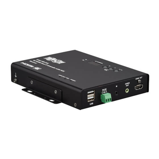
HDMI over IP 4K Extender Receiver
with PoE: B162-100-POE
Este manual está disponible en español en la página de Tripp Lite: tripplite.com/support
Ce manuel est disponible en français sur le site Web de Tripp Lite : tripplite.com/support
Owner's Manual
WARRANTY REGISTRATION
Register your product today and be
automatically entered to win an ISOBAR
surge protector in our monthly drawing!
tripplite.com/warranty
1111 W. 35th Street, Chicago, IL 60609 USA • tripplite.com/support
Copyright © 2021 Tripp Lite. All rights reserved.
®
1
Advertisement
Table of Contents

Related Manuals for Tripp Lite B162-100-POE


Summary of Contents for Tripp Lite B162-100-POE
- Page 1 HDMI over IP 4K Extender Receiver with PoE: B162-100-POE Este manual está disponible en español en la página de Tripp Lite: tripplite.com/support Ce manuel est disponible en français sur le site Web de Tripp Lite : tripplite.com/support WARRANTY REGISTRATION Register your product today and be automatically entered to win an ISOBAR ®...
-
Page 2: Table Of Contents
Table of Contents 1. FCC Information 10. System Settings 10.1 Overview 2. User Notice 10.2 General Settings 10.3 Transmitter Settings 3. Package Contents 10.4 Receiver Settings 4. Introduction 10.5 Batch Configuration 10.6 Maintenance 5. Product Features 10.6.1 Upgrading Device Firmware 10.6.2 Synchronizing All Devices 6. -
Page 3: Fcc Information
The user must use shielded cables and connectors with this equipment. Any changes or modifications to this equipment not expressly approved by Tripp Lite could void the user’s authority to operate this equipment. -
Page 4: Introduction
4. Introduction The Tripp Lite B162 HDMI over IP Extenders deliver visually lossless 4K signals with low latency over long distance via a standard Gigabit Ethernet switch. Tripp Lite’s solution is designed to address the challenges that system integrators encounter when implementing AV over IP solutions. - Page 5 5. Product Features Note: • B162 PoE extenders can be installed in combination with PoE Ethernet switches to reduce power cabling and additional power outlets. Spontaneous Scheduling Management • Offers a user-friendly scheduling management function for users to pre-plan the display schedule. •...
- Page 6 5. Product Features Web GUI-Based Management: No Additional Server PCs or Software Required • Simple access – users can use the browser or IP address to link directly to the DVOE Manager. Go Further For Less with Daisy-Chaining • Connects multiple displays through a single port to utilize every port of the Ethernet switch and maximize its value. •...
-
Page 7: Getting Started
Embedded / De-Embedded Audio Support • Separate audio signal can be embedded into the HDMI stream (B162-001-POE only). • Audio stream can be extracted from the HDMI stream and delivered as a separate audio signal (B162-100-POE only). Multiple Control Channels •... -
Page 8: Hardware Setup
7. Hardware Setup 7.1 Components Before proceeding to hardware setup: •Review the safety information regarding the placement of this device in Important Safety Instructions. •Do not power on the device until all necessary hardware is connected. B162-001-POE Front View AUDIO RS-232 Tx GND Rx B162-001-POE... - Page 9 (transmitter) for the receiver. Link LED – Lights orange to indicate the LAN Port 1 is connected to an Ethernet switch. Power LED – Lights green to indicate the unit is receiving power. B162-100-POE Front View RS-232 AUDIO Tx GND Rx USB-A Ports –...
- Page 10 LAN 1 Port with PoE – Connects a Gigabit Ethernet cable to the LAN. LAN 2 Port (no PoE) – Connects to another B162-100-POE with an Ethernet cable in a daisy-chain setup. DC Power Jack – Connects the DC Power Adapter to provide power to the receiver.
-
Page 11: Mounting The Device
7. Hardware Setup 7.2 Mounting the Device Wall Mount Secure or hang the B162 unit on a wall using the built-in mounting brackets. -
Page 12: Connecting The Device
7. Hardware Setup 7.3 Connecting the Device Follow the steps below to connect your B162 units with the hardware as required. Note: For details on LED indicators to help you identify connection status or signal transmission, see Status LEDs. 1. Connect the transmitter’s HDMI Input to the video source device with a user- provided HDMI cable. - Page 13 7. Hardware Setup Notes: • The IR, RS-232 and USB signal transmissions are disabled by default. To enable them, go to System Settings>Receiver>IR/RS232 or USB in DVOE Manager and select the signal source. • Each transmitter can be controlled by 4 USB touchscreens connected to receivers. •...
-
Page 14: Panel Operation
8. Panel Operation 8.1 Overview This chapter provides information on panel LEDs and instructions to operate the B162 units using the panel buttons. 8.2 Status LEDs Both the transmitter and receiver have front-panel LEDs that indicate their operating and power status. Indicator Description Power... -
Page 15: Panel Controls
4. Tx/Rx Switch Button – Press to switch control between a receiver and its corresponding transmitter. Notes: • The B162 unit automatically locks its panel when it idles for 1 minute. To unlock, press and hold the Down button for 3 seconds. • Tx/Rx LEDs and Tx/Rx Switch button are available only on B162-100-POE receivers. -
Page 16: Assigning Sources Using The Device Panel
8.4 Assigning Sources Using the Device Panel 1. Assign an ID number to each of your B162-100-POE devices: a. On the B162-100-POE, make sure the control is switched to Rx, in which case the Rx LED lights up. If not, press the Tx/ Rx Switch button. - Page 17 9. Management 1. Open a web browser and type the IP address you obtained using IP Installer Utility. The following screen appears: 2. Select Administrator for User Level and type password for the Password field. The following screen appears upon initial login. Note: If you are the administrator logging in for the first time, use the default password: password.
- Page 18 9. Management 4. Click Next. The following screen appears. The setup wizard lists the B162 transmitters and receivers found in the network. 5. To configure device IP addresses, select the devices from the list and click Next. The following screen appears: 6.
- Page 19 8. To reassign device IDs, click and type a new ID for the target B162 device. 9. Click Done. The DVOE Manager’s main screen appears. Notes: • For security reasons, Tripp Lite recommends changing the password at first login. For details on account settings, see Account Settings. • To access these settings again, click...
-
Page 20: The Main Screen
9. Management 9.4 The Main Screen You can access the following controls from the DVOE Manager’s main screen: 6 7 8 Previews for Video Walls and Receivers – Shows a preview of created video walls, individual video receivers and daisy-chain setups. -
Page 21: Apply/Auto Apply
9. Management 9.4.1 Apply/Auto Apply If you wish to apply settings as you configure them, check Auto Apply. Alternatively, if you wish to manually apply the settings, uncheck Auto Apply and use the Apply button. The button will light up to show a change was made. - Page 22 4. When there is a display issue from a single connected receiver, the preview is shown below. Alternatively, you can go into system settings to assign sources there. Follow the steps below: 1. From the main screen, click , and then click the Receiver tab. The managed B162-100-POE receivers appear.
- Page 23 9. Management 2. Assign a source for each of the B162-100-POE receivers. a) Move the cursor to a receiver. A green arrow appears at the top right corner of the receiver preview window. b) Click the green arrow. A dropdown menu appears.
-
Page 24: Configuring And Setting Up A Video Wall
9. Management 9.6 Configuring and Setting Up a Video Wall To configure a video wall, follow the steps below. 1. Make sure you have created a video wall template for your specific needs. For detailed steps, see Creating a Video Wall Layout. - Page 25 9. Management 2. Configure your video wall layout as required. Use the preview to help you visualize the layout. Control Description Name of Video Wall Type the name of your video wall. Number of Displays Define the following parameters. Horizontal and Vertical: Click the dropdown boxes to select the number of displays for your video wall.
-
Page 26: Editing A Video Wall Layout
9. Management 3. From the preview area, click the dropdown boxes to define the output receiver for each monitor. An already selected, unavailable receiver is marked with an asterisk (*). 4. Click Create. The new video wall template is created. 9.6.2 Editing a Video Wall Layout To edit a video wall layout from the DVOE Manager’s main screen, click the top right corner of the layout you wish to edit, and then select Edit. -
Page 27: Editing A Preview
9. Management 9.6.3 Editing a Preview You can edit the following settings for a video wall layout: Operation Mode – Click the dropdown list to select an operation mode. Assigned Receiver – Displays the assigned receiver for the display. For an unmerged display, double-click the display to open the settings page for the assigned receiver. -
Page 28: Creating A Profile
9. Management 9.7.1 Creating a Profile Follow the steps below to create a profile. 1. On the main screen, click the profile arrow on the profile bar for the profile list shown below: 2. Click +Add Profiles for the page below: •... -
Page 29: Editing, Deleting And Disconnecting A Profile
9. Management 9.7.2 Editing, Deleting and Disconnecting a Profile On the profile list, you can edit, delete and disconnect profiles. Click to select the profile you wish to configure and a green arrow will appear. Click the green arrow for a dropdown menu of edit, delete and disconnect options. Edit To edit the profile, click the Edit option: •... -
Page 30: Select/Apply A Profile
9. Management 9.7.3 Select/Apply a Profile After creating the profile, you can apply the settings of the profile to the video displays. Follow the steps below to apply the settings: 1. Bring up the profile list. 2. Click to select a profile and a preview will be shown: The video receiver/video wall selected in the profile will be displayed. - Page 31 9. Management 2. Click to select the day and time period to set up the schedule. An example is shown below: 3. Edit/add the schedule as required: • Status: Enable or disable the schedule. • Profile: Select a profile. • Start Date: Select or enter a start date. •...
-
Page 32: Managing B162 Devices
9. Management 9.8 Managing B162 Devices 9.8.1 Checking B162 Status You can check the statuses of your B162 devices by clicking , from the main screen, and then the Transmitter or Receiver tab. The status for a B162 device is indicated with a colored circle. See the table below for status indicators and the corresponding descriptions. -
Page 33: System Settings
10. System Settings 10.1 Overview The System Settings page allows you to specify device date and time, configure settings of connected B162 devices, upgrade device firmware and back up the DVOE Manager’s settings. 10.2 General Settings The General tab contains the date, time and panel lock settings. , from the main screen, and then click the General tab. -
Page 34: Transmitter Settings
10. System Settings 10.3 Transmitter Settings The Transmitter tab displays the managed B162-001-POE transmitter devices and provides access to the settings. To access transmitter settings, follow the steps below: 1. From the main screen, click the gear icon and then click the Transmitter tab. The managed B162-001-POE transmitters appear. 2. - Page 35 10. System Settings 4. Click Configuration. This window appears. 5. Configure the settings as required. • Name: Click to rename the transmitter. • IP Address: Specifies how the transmitter obtains its IP address. By default, this field is set to System Auto. o DHCP: Select this option to have the IP address automatically assigned by a DHCP server.
-
Page 36: Receiver Settings
1. From the main screen, click the gear icon, and then click the Receiver tab. The managed B162-100-POE receivers appear. 2. Move the cursor to a receiver you wish to configure. A green arrow appears at the top right corner of the receiver preview window. - Page 37 • Fast Switching: Click to define the resolution for fast switching. Note: For best results, Tripp Lite recommends setting this field to the same resolution as your video source and make sure this setting is identical on all B162-100-POE receivers.
-
Page 38: Batch Configuration
10. System Settings 10.5 Batch Configuration A batch configuration option is available for both Transmitters and Receivers. It appears on the top right corner of the page as Quick Configuration. If you wish to adjust a particular setting for a group of devices, do the following: 1. -
Page 39: Maintenance
10. System Settings 10.6 Maintenance The Maintenance tab allows you to upgrade device firmware, back up transmitter and receiver layouts and restore devices to previously backed up settings. 10.6.1 Upgrading Device Firmware To upgrade firmware, follow the steps below. 1. From the main screen, click the gear icon and click the Maintenance tab. The following screen appears. The Firmware Upgrade section lists the detected transmitter and receiver devices and their firmware versions. -
Page 40: Backing Up Device Settings
10. System Settings 10.6.3 Backing Up Device Settings You can export transmitter and receiver layouts for backup or migration purposes. 1. From the main screen, click the gear icon and then click the Maintenance tab. This screen appears: 2. Click Backup. A confirmation message appears when the backup is complete. 10.6.4 Restoring Device Settings You can restore your DVOE Manager to a previously saved set of settings on transmitter and receiver layouts. -
Page 41: Recovery Mode
Account Level Default Password Privileges Administrator password All settings User password Source assignment and B162-100-POE receiver allocation on video wall layouts only To change the default password, click the gear icon from the main screen and then click the Account tab. -
Page 42: Cli Commands
11. CLI Commands 11.1 Overview You can manage and configure the B162 devices using Telnet, TCP or RS-232 commands from a PC. 11.2 Before You Start Make sure you have installed a PC to the Ethernet switch in your setup, as illustrated below:... -
Page 43: Executing Commands
2. Depending on the supported command type for your PC, do the following to connect to your deployment: • Telnet connections - In the command prompt, type the IP address of any B162-100-POE receiver in your setup and use port 23. For example: •... -
Page 44: Commands
• To switch the source to a B162-001-POE transmitter with the IP address of 10.0.90.11 to the B162-100-POE receiver you used to make the CLI connection, type sw i10.0.90.11 on • To switch the source to a B162-001-POE transmitter with the ID of 1 on a B162-100-POE receiver with the ID of 5, type sw i1 o5 on •... -
Page 45: Switching Video, Usb
Ends the command. Examples: • To switch the video path of a B162-001-POE transmitter with the ID of 3 to a B162-100-POE receiver with an ID of 4, type sw i3 video o4 • To switch the USB path of a B162-001-POE transmitter with the ID of 1 to a B162-100-POE receiver with an ID of 6, type sw i1 usb o6 11.4.4 Disabling Video, USB, RS-232 and/or IR Paths... -
Page 46: Displaying Port-Switching Alerts
Sends an alert in the command prompt window to inform port switching configuration. For example, when the user assigns the B162-001-POE with the device ID of 2 to the B162-100-POE with the device ID of 3, the system sends this message in the command prompt window: sw o2 i3 on Disables the alert for port switching. -
Page 47: Configuring Video Wall Settings
• To apply Layout 1 to a video wall with the ID of 8c8f12e62d3c87ef and assign the source connected to B162-001-POE (device ID: 2) to the video wall, where one display is connected to B162-100-POE (IP address: 10.0.66.73), type the following: vw + f8c8f12e62d3c87ef + lLayout 1 + o10.0.66.73 + i2 + on... -
Page 48: Disabling A Video Output
• To display the OSD of a B162-100-POE receiver with the IP address 10.0.90.22, type osd o10.0.90.22 on • To hide the OSDs of the B162-100-POE receivers for a video wall with the Video Wall ID 0, type osd f0 off... -
Page 49: Configuring Edid Mode
Indicates the device ID of the target input device (B162-001-POE). Use an asterisk (*) to target all transmitters in the environment. o<port> Indicates the device ID of the target output device (B162-100-POE). Use an asterisk (*) to target all receivers in the environment. \r\n Ends the command. -
Page 50: Setting The Baud Rate
11.4.14 Displaying Device Status You can display the status of B162 transmitters or receivers or the connection status of B162-001-POE transmitters to B162-100-POE receivers. To do this, type the command in this format: read + [i<port>] | [o<port>] + \r\n Control Description i<port>... -
Page 51: Important Safety Instructions
12. Important Safety Instructions 12.1 General Safety Instructions • This product is for indoor use only. • Read all of these instructions. Save them for future reference. • Follow all warnings and instructions marked on the device. • Do not place the device on any unstable surface (cart, stand, table, etc.). If the device falls, serious damage will result. •... -
Page 52: Specifications
13. Specifications Function B162-100-POE (Output) B162-001-POE (Input) Video Output/Input Interfaces (1x) HDMI (Female) 100 Ω Impedance Maximum Distance Video Maximum Data Rate Avg: 150 ~ 500 Mbps Compliance HDMI (4K), HDCP Max. Resolutions/Distances 4096 x 2160 (@ 30 Hz) with 4:4:4 @... -
Page 53: Supported Browsers
13. Specifications Function B162-100-POE (Output) B162-001-POE (Input) Physical Properties Housing Metal Weight 1.5 lb. (0.68 kg) Size (L x W x H) w/Bracket 6.7 x 5.78 x 1.18 in. (17.02 x 14.69 x 3 cm) Size (L x W x H) w/o Bracket 6.54 x 4.92 x 1.14 in. -
Page 54: Warranty And Registration
1-Year Limited Warranty TRIPP LITE warrants its products to be free from defects in materials and workmanship for a period of one (1) year from the date of initial purchase. TRIPP LITE’s obligation under this warranty is limited to repairing or replacing (at its sole option) any such defective products. To obtain service under this warranty, you must obtain a Returned Material Authorization (RMA) number from TRIPP LITE or an authorized TRIPP LITE service center. - Page 56 1111 W. 35th Street, Chicago, IL 60609 USA • tripplite.com/support 21-03-154 • 93-3DE2_RevA...