
Related Manuals for Pentair Pool Products Acu-Tol AT8

Summary of Contents for Pentair Pool Products Acu-Tol AT8
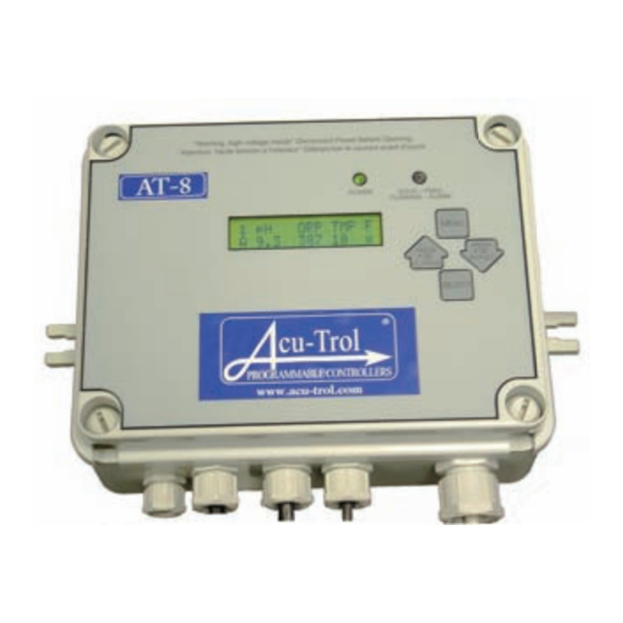
- Page 1 AT8™ Pool and Spa Controller Installation and Operation Guide For Software Version AT-8-1.6 800-831-7133 www.pentaircommercial.com www.pentairpool.com...
-
Page 3: Table Of Contents
TABLE OF CONTENTS ChApTEr 1 INFOrMATION .............4 SAFETY PRECAUTIONS ....................4 WARRANTY ........................4 AT-8 OVERVIEW ......................5 ImPORTANCE OF WATER mAINTENANCE ..............5 ChApTEr 2 AT-8 SpECIFICATIONS ..........6 ChApTEr 3 INSTALLATION ............7 INSTAllATION PREPARATION ..................7 INSTAllATION SUmmARY .................... 7 FlOW CEll INSTAllATION .................. - Page 4 WARRANTY Pentair Acu-Trol warrants the AT-8 to be free from defects in manufacturing and workmanship for a period of one (1) YEAR from the date of manufacture for the electronic module. All commercial pH and ORP sensors have a warranty of two (2) years. Flow cells have a warranty of one (1) year.
-
Page 5: Chapter 1 Information
CHAPTER 1 INFORmATION SAFETY PRECAUTIONS PlEASE REAd THIS USER mANUAl completely before installing or operating the equipment. The AT-8 is a Class 1 product for protection against electric shock and a Type 1 product with regards to disconnection of the control circuits. be sure to observe the following safety precautions: •... -
Page 6: 1.3 At-8 Overview
1.3 AT-8 OVERVIEW Acu-Trol, the technological leader in swimming pool automation, congratulates you on your selection of the AT-8 swimming pool controller. The AT-8 will maintain the pH and sanitizer levels,and monitor and report temperature levels. The AT-8 features: • Easy Read Display: The AT-8 uses an easy to read lCd display screen. -
Page 7: Specifications
ChApTEr 2 AT-8 SpECIFICATION Inputs: TEmPERATURE (10K probe) FlOW (switch only) Display Range: 0.1 – 9.9 +/- 0.1 450 – 999mV +/- 2 TEMP 15 – 150 +/- 1 FLOW ON / OFF Calibration Range: +/- 0.9 +/- 125 TEMP +/- 50 Output Relays: 110/220 VAC 6A... -
Page 8: Chapter 3 Installation
CHAPTER 3 INSTAllATION Installation Preparation Receipt Inspection: Upon receiving the controller from shipping, check the carton carefully. Report any damaged items directly to the shipping company. Examine the shipping list and verify that all items are present. Please contact your local Acu-Trol dealer if any items are missing or have been damaged. Use care when unpacking equipment to avoid damage or loss of small parts. -
Page 9: Flow Cell Installation
AK1200 Flow Cell Installation 3.3.1 Tools & Supplies Needed In order to install the AK1200 flow Cell, you will need A Phillips screwdriver A drill A 1/4" drill bit A 1/4" NPT tap A small flat head screwdriver A 1/2" poly tubing Remove flow cell from shipping carton and make sure all parts are included with AK1200 flow cell. - Page 10 3.3.4 mounting the Flow Cell Select a suitable location for the flow cell meeting the following recommendations: • The sensors should be away from direct sunlight, as this may affect the readings. • The location should be where some water spillage will not damage anything. Preferably below the level of the controller.
- Page 11 WArNINg Securely fasten all electrical, water, and chemical lines. Locate chemical feed pumps and chemical storage tanks in a safe and secure area. WArNINg Check filter daily for debris buildup and clean as needed. To clean filter, turn the flow cell inlet and exit valves OFF, remove filter cover and filter, being careful not to loose seal.
-
Page 12: Installation
AT-8 Installation 3.4.1 mounting location Select a location for mounting the AT-8, meeting the following conditions 1. At least ten (10) feet from open water. 2. Close enough for the supplied power cord to reach the supply voltage. The controller will not operate properly without a solid earth ground connection. 3. - Page 13 3.5.1 Internal Wiring Connections 3.5.1.1 110 VAC Feed System Set Up The AT-8 comes from the factory set for 110 VAC. before applying power to unit make sure unit is still set for 110vac. Inspect JP2 (located between fuses and transformer) and ensure the two black jumpers are connected between 1-2 and 3-4.
- Page 14 3.5.1.4 Installing 220 VAC Feeders To wire your 220vac feeder directly to the AT-8 cut and strip the wires 1/4” back and either tin the ends or attach a wire ferrule. • BELOW Terminal Block AC IN = plug or power to AT-8 ORP NO = Sanitizer relay output with normally open relay (no power until relay turned on) ORP NC = sanitizer relay output with normally closed relay...
- Page 15 3.5.1.7 line Voltage (Input Voltage) Sanitizer Output Voltage • Remove all jumpers on JP1. • Place a jumper between pins 1 and 3. • Place a second jumper between pins 2 and 4. • JP1 is now configured for line voltage. WArNINg Power should be off to the AT-8 beforemoving JP1 jumpers.
- Page 16 3.5.1.10 bus Connection • Run the Ethernet wire through the large strain reliefs on the bottom of the AT-8. • The strain relief must be unassembled before inserting the bus wire • Connect the Ethernet wire to either of the connectors. multiple AT-8 Setup •...
-
Page 17: Chapter 4 Sensors
CHAPTER 4 SENSORS The AT-8 can accept readings from a wide variety of sensors. Each sensor has its own unique circuitry that is con- nected directly to the micro-controller for measurement. Isolation of each sensor ensures more accurate measure- ments. The AT-8 measures the following sensor measurements with the listed characteristics: Range: 4.22 to 9.78, ±0.02. -
Page 18: Flow Sensors
Flow Sensors The AT-8 is able to recieve information from one flow switch, provided with the Ak1200 flow cell This flow switch is used to indicate flow through the flow cell and determines when it is OK to feed chemicals in to the system. The AT-8 will not allow chemicals to feed if there is no flow in the system. -
Page 19: Chapter 5 Operation And Programming
CHAPTER 5 OPERATION ANd PROgRAmmINg Overview: The AT-8 system controller is designed to accommodate any size water system. Once the controller is installed it is ready to be programmed. The system comes from the factory with default programming and should only require a small amount of adjustments to work with the size of body of water and chemical feeder of your system. - Page 20 5.1.1 System Number • If you have multiple bodies of water being monitored each unit will have it’s information displayed for 5 seconds. If you have 4 bodies of water then every 20seconds all bodies of water will have been viewed once. •...
- Page 21 5.1.5 Flow • An “X” is displayed under the “F” on the right side when there is flow. NOTE: if there is no “X” (no flow) then the feed relays are locked out. TMP F 78 X 5.1.6 Indication of Safety lockout •...
-
Page 22: Setup
AT-8 Set Up before you begin programming your AT-8, you will want to set up the basic system in the set up menu. The set up menu will allow you to program the date and time in to the AT-8, program and or enter your password to access the controller, as well as view the serial number and software version specific to your controller. - Page 23 5.2.3 Reset All Safety This screen will allow you to reset all the safety or overfeed timers in your AT-8 units. RESET ALL SAFETY • Press SELECT. • Use the up and down arrows to select either “yes” or “no”. •...
-
Page 24: Ph Programming
5.2.7 Enter Password ENTER PASSWORD To enter a password in your AT-8 controller: • Using the up and down arrows scroll through the numbers until the current password is displayed (factory default is “A”). Press SELECT to choose the character and move on to the next characer in the sequence. . Press SElECT again when your entire pasword is showing to enter the pasword in the controller. - Page 25 5.3.1 Reading/ CAL # pH Reading / CAL 1 pH : 2.5 • Displays the current calibrated reading of the pH • If the reading needs to be corrected, use the up and down arrows to add or subtract the amount of calibration.
- Page 26 5.3.5 pH Feed Cycle pH FEED CYCLE MINUTES : 2:00 • This is the total amount of time in minutes and seconds of your feed and mix cycle. Use the up and down arrows to adjust this time to accommodate your system. See FEED LIMIT below for example.
- Page 27 5.3.8 pH Feed Safety # pH FEED SAFETY MINUTES:* • This is the overfeed safety feature of the system. Determine the total amount of time you want your pH feeder to come on in a 24 hr period and enter it here. The 24 hr period starts when you power up your controller.
- Page 28 5.3.10 pH High Alarm # pH HIGH ALARM pH : • Use the up and down arrows to adjust the alarm for the high end of your desired pH range. This alarm will turn on the alarm light and make the pH reading flash. •...
-
Page 29: Orp Programming
ORP Programming To program your AT-8, you will need to enter the program sub menu. Starting from the reading screen. Press the mENU button to scroll through the available sub-menus. Press the mENU button Again 10-May-06 14:48 press SElECT to enter the AT-8 Setup submenu. PROGRAM SUBMENU You will need to enter your password before the AT-8 will allow you to enter the programming menu. - Page 30 5.4.2 ORP Sensor # Offset ORP SENSOR Offset • This shows you how much calibration you have on the probe. In the above example an uncalibrated probe that read 690, but was changed to read 700 will have an offset of If the offset value gets to high it may be an indication of aged or malfunctioning probe.
- Page 31 5.4.6 ORP Feed Safety # ORP FEED SAFETY MINUTES:* • This is the overfeed safety feature of the system. Determine the total amount of time you want your ORP feeder to come on in a 24 hr period and enter it here. The 24 hr period starts when you power up your controller.
- Page 32 5.4.10 ORP Prop Feed # ORP PROP FEED PROP FEED: • Use the up and down button to turn this feature ON or OFF. Turning the proportional feed on will proportionately feed the pH chemical within a 30 ORP range. •...
-
Page 33: Temperature Programming
Temperature Programming To program your AT-8, you will need to enter the program sub menu. Starting from the reading screen. Press the mENU button to scroll through the available sub-menus. Press the mENU button Again 10-May-06 14:48 press SElECT to enter the AT-8 Setup submenu. PROGRAM SUBMENU You will need to enter your password before the AT-8 will allow you to enter the programming menu. - Page 34 NOTE: pH probes can only be calibrated +/- 50 units. • Press – SELECT to save and go on or press mENU to not save and return to reading screen. 5.5.2 Temperature Sensor # Offset TEMP SENSOR Offset • This shows you how much calibration you have on the probe. In the above example an uncalibrated probe that read 68, but was changed to read 70 will have an offset of 2.
- Page 35 5.5.5 Temperature High Alarm # TEMP HIGH ALARM TEMP : • Use the up and down arrows to adjust the alarm for the high end of your desired pH range. This alarm will turn on the alarm light and make the TEMP reading flash. •...
-
Page 36: Data Submenu
data Submenu before you begin programming your AT-8, you will want to set up the basic system in the set up menu. The set up menu will allow you to program the date and time in to the AT-8, program and or enter your password to access the controller, as well as view the serial number and software ver- Starting from the reading screen. - Page 37 5.6.3 log Contents This allows viewing of the stored data. LOG CONTENTS ARROWS TO REVIEW Use the UP arrow to scroll from the oldest to the newest record and dOWN arrow to scroll from the newest to the oldest. • FORMAT TOP lINE: # mmddYY HH:mm C # = unit number for this record.
-
Page 38: Chapter 6 Maintenance
CHAPTER 6 mAINTENANCE Calibration maintenance Periodically a hand check of the systems water must be performed to compare against the read- ings of the controller. Use an AcuCheck 3 or a professional test kit and if needed perform a cali- bration. -
Page 39: Chapter 7 Troubleshooting
CHAPTER 7 TROUblESHOOTINg 6.1.1 Readings are Fluctuating • Check the flow in the flow cell. The flow sensor magnet should be just making contract with the flow sensor. Too much flow can cause inaccurate readings and decrease sensor life. • Check the pressure in the flow cell. -
Page 40: Chapter 8 Menu Trees
CHAPTER 8 mENU TREE AT-8 and AT-8S Menu Tree- SET UP 2009 AT8 Manual... - Page 41 AT-8 and AT-8S Menu Tree- pH Programming 2009 AT8 M anual...
- Page 42 AT-8 and AT-8S Menu Tree- pH Programming 2009 AT8 Manual...
- Page 43 AT-8 and AT-8S Menu Tree- Temperature Programming 2009 AT8 M anual...
- Page 44 AT-8 and AT-8S Menu Tree- Data Log Programming 2009 AT8 Manual...