
Related Manuals for Bunn T3


Summary of Contents for Bunn T3
- Page 1 BUNN ® T3,T3A T6,T6A OPERATING & SERVICE MANUAL BUNN-O-MATIC CORPORATION POST OFFICE BOX 3227 SPRINGFIELD, ILLINOIS 62708-3227 TELEPHONE: (217) 529-6601 FAX: (217) 529-6644 10145.0000G 7/00 © 1984 Bunn-O-Matic Corporation...
-
Page 2: Table Of Contents
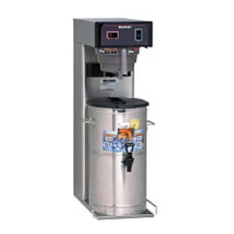
Wiring Diagrams ... 28 The T3 will brew a three-gallon batch of fresh tea into a reservoir, the T6 will brew a three-gallon batch into either the right or left reservoir. The tea will be dispensed at approximately room temperature to conserve ice. -
Page 3: User Notices
Carefully read and follow all notices on the equipment and in this manual. They were written for your protec- tion. All notices on the equipment should be kept in good condition. Replace any unreadable or damaged labels. #00831.0000 #00656.0000 #03408.0000 #03409.0000 USER NOTICES Page 3... -
Page 4: Electrical Requirements
" water supply line. A tight coil of copper tubing in the water line will facilitate moving the brewer to clean the countertop. Bunn-O-Matic does not recommend the use of a saddle valve to install the brewer. The size and shape of the hole made in the supply line by this type of device may restrict water flow. -
Page 5: Initial Set-Up
Insert the funnel into the funnel rails and push it until it stops. Rotate the funnel handle to the left or right (T6) to align the funnel discharge over the hole in the reservoir cover. (Model T3 funnel does not rotate.) -
Page 6: Adjusting Brew Volumes
INITIAL TIMER ADJUSTMENT (cont.) 10. Install the ferrule and screen in the funnel. Load the funnel with a BUNN ounces of loose tea leaves. Depress the start button to brew tea and observe the funnel drip out and the dilution streams near the end of the cycle. The dilution stream should stop approximately thirty seconds after the drip out has stopped. -
Page 7: Cleaning
CAUTION - DO NOT KEEP BREWED ICED TEA OVERNIGHT. THE SERVER MUST BE CLEANED DAILY. 1. Begin each brew cycle with a clean empty brew funnel and reservoir(s). ® 2. Insert a BUNN filter into the funnel. 3. Pour the packet of loose fresh tea leaves into the filter. Approximately four ounces is recommended. -
Page 8: Troubleshooting
A troubleshooting guide is provided to suggest probable causes and remedies for the most likely problems encountered. If the problem remains after exhausting the troubleshooting steps, contact the Bunn-O-Matic Technical Service Department. • Inspection, testing, and repair of electrical equipment should be performed only by qualified service person- nel. - Page 9 CAUTION - Do not eliminate or by- pass limit thermostat or thermal cut-off. Use only BOM replacement part #29329.1000 2. Control Thermostat 3. Tank Heater 1. (A) ON/OFF Switch (T3) (B) Selector Switch (T6) 2. Start Switch 3. Dilution Timer Page 9 REMEDY Refer to Service - Start Switch for testing procedures.
- Page 10 TROUBLESHOOTING (cont.) PROBLEM Dilution cycle will not start (cont.) Inconsistent beverage level in dis- penser Consistently high or low beverage level in the dispenser PROBABLE CAUSE 4. Dilution Solenoid Valve 1. Internal Flow Control (.195 GPM) 2. Syphon System 3. Lime Build-up CAUTION - Tank and tank compo- nents should be delimed regularly depending on local water condi-...
- Page 11 TROUBLESHOOTING (cont.) PROBLEM Spitting or excessive steaming Drip-out time too long Dripping from sprayhead Water flows into tank continuously (ON/OFF or Slector Switch "ON") Water flows into tank continuously (ON/OFF or Selector Switch "OFF") PROBABLE CAUSE 1. Lime Build-up CAUTION - Tank and tank compo- nents should be delimed regularly depending on local water condi- tions.
- Page 12 A six-hole stainless steel spray- head must be used for proper ex- traction. The BUNN ® paper filter must be centered in the funnel and the bed of tea leaves leveled by gentle shak- ing.
- Page 13 2. Plumbing Lines 3. Water Supply 4. Tank Heater Page 13 REMEDY ® The BUNN paper filter must be centered in the funnel and the bed of grounds leveled by gently shak- ing. The nut on the solenoid(s) must be tight or it will vibrate during opera- tion.
-
Page 14: Service
SERVICE This section provides procedures for testing and replacing various major components used in this brewer should service become necessary. Refer to Troubleshooting for assistance in determining the cause of any problem. WARNING - Inspection, testing, and repair of electri- cal equipment should be performed only by qualified service personnel. -
Page 15: Brew Solenoid Valve
2. Disconnect the white/violet and white/green wires from the solenoid valve. With the ON/OFF or SE- LECTOR switch in the "ON" (T3 left, T6 Left or right) position and press the start switch. 3. With a voltmeter, check the voltage across the white/violet and white/green wires. - Page 16 SERVICE (cont.) BREW SOLENOID VALVE (cont.) WHI/BLU to Dilution Timer TL4 WHI/GRN to BREW Timer TL4 WHI/VIO to Dilution Solenoid DILUTION SOLENOID BREW SOLENOID YEL to Selector Switch WHI/VIO to Brew Solenoid WHI/GRN to Brew WHI/VIO to Brew Timer TL1 Timer TL4 WHI/VIO to Brew Timer TL1...
-
Page 17: Brew Timer (Early Models)
2. With a voltmeter, check the voltage across termi- nals TL1 and TL2 when the ON/OFF or SELECTOR switch is in the “ON” (T3 left, T6 left or right) po- sition. Connect the brewer to the power source. The indication must be: a) 120 volts ac for two wire 120 volt models. -
Page 18: Digital Brew Timer (Late Models)
SERVICE (cont.) DIGITAL BREW TIMER (Late Models) FIG. 6 DIGITAL BREW TIMER Location: The timer is located inside the hood, attached to the left side. Test Procedure. NOTE: Do not remove or install wires while timer board is installed. Pressure applied to one side may cause damage to the board. - Page 19 SERVICE (cont.) DIGITAL BREW TIMER (Late Models)(cont.) 1. Modifying brew volumes. To modify a brew vol- ume, first check that the SET/LOCK switch is in the “SET” position on the circuit board. To increase a brew volume, place the ON/OFF switch in the “ON”...
-
Page 20: Control Thermostat
SERVICE (cont.) CONTROL THERMOSTAT FIG. 8 CONTROL THERMOSTAT Location: The control thermostat is located inside hood on the right side just behind the dilution timer. Test Procedures: 1. Disconnect the brewer from the power source. 2. Locate the blue/black wire on the control thermo- stat. -
Page 21: Dilution Solenoid Valve
Location: Viewing the brewer from the rear the dilution so- lenoid for the T3 is mounted on the center of the sole- noid mounting bracket, the T6 solenoids are mounted in the center and the right side of the mounting bracket. -
Page 22: Dilution Timer
5. With a voltmeter, check the voltage across termi- nals TL1 and TL4 when the ON/OFF or selector switch is in the "ON" (T3 left, T6 left or right) po- sition and the start switch is momentarily placed in the lower position. Connect the brewer to the power source. -
Page 23: Limit Thermostat
SERVICE (cont.) LIMIT THERMOSTAT FIG. 13 LIMIT THERMOSTAT Location: The limit thermostat is located inside the hood on the tank lid. Test Procedure: 1. Disconnect the brewer from the power source and remove the black wire from the limit thermostat. 2. -
Page 24: On/Off Switch & Selector Switch
If continuity is not present as described, replace the switch. 7. On T3 brewers disconnect the pink and gray wires from the left and center terminals. 8. Check for continuity across the left and center ter- minals in rows two, three and four with the switch in the half batch position. - Page 25 SERVICE (cont.) ON/OFF SWITCH (T3 W/OUT HALF BATCH) or SE- LECTOR SWITCH (T3 W/HALF BATCH and T6 BREWERS)(cont.) T6 Brewers 1. Disconnect the brewer from the power source. 2. Remove the black wire from the top center switch terminal. 3. With a voltmeter, check the voltage across the black wire removed from the selector switch and the white wire or red wire on the tank heater.
-
Page 26: Start Switch
SERVICE (cont.) START SWITCH FIG. 17 START SWITCH Location: The start switch is located in the right front of the hood. Test Procedure: 1. Disconnect the brewer from the power source. 2. Remove the wires from all four terminals. 3. Check for continuity across the two terminals on the right side of the switch when it is held in the lower position. -
Page 27: Tank Heater
SERVICE (cont.) TANK HEATER FIG. 19 TANK HEATER Location: The tank heater is located inside the tank and se- cured to the tank lid. Test Procedures: 1. Disconnect the brewer from the power supply. 2. With a voltmeter, check the voltage across the black and white wires on 100 volt and 120 volt models or the black and red wires for 240 volt models. -
Page 28: Wiring Diagrams
10145 072600 Page 28... - Page 29 10145 072600 Page 29...
-
Page 30: Wiring Diagrams
10145 072600 Page 30...