
Summary of Contents for Pyramid APEX 5000 Series
- Page 1 5000 7000 APEX SERIES & BILL ACCEPTOR INSTALLATION/OPERATION MANUAL Pyramid Technologies, Inc. 1718 North Quail Mesa, Arizona 85205 USA 480-507-0088 FAX: 480-507-1922 www.pyramidacceptors.com Rev. V 06/28/11...
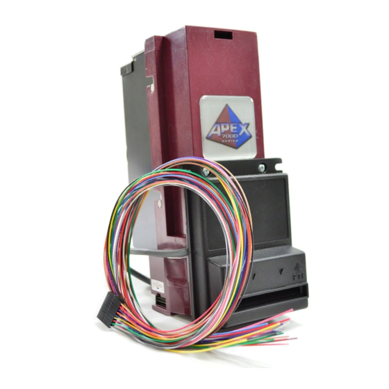
- Page 2 Apex 5000. Product Overview The Pyramid Technologies, Inc. (PTI) Apex Series bill acceptors are designed for indoor use in the amusement, gaming, lottery and kiosk markets. Based on the model, the Apex acceptors can accept: $1 & $5 bills, $1, $5, $10 and $20 bills, or $1, $5, $10, $20, $50 and $100 bills.
- Page 3 For Dimensional Drawings, please visit our website at www.pyramidacceptors.com in the Bill Acceptors section. Accessories The following is a list of optional accessories available from Pyramid Technologies, Inc. See our website for additional items, photos, and information about accessories. Description Part Number...
- Page 4 firmware version, plug it into the Apex, and the update happens automatically. The PRO-1 is powered by the bill acceptor when connected, so there is no need for a battery or power supply. USB Flash Download Cable P/N 05AA0026 The USB Flash Download Cable is used to update bill acceptors with new firmware via Windows PC, and perform Configuration and Diagnostic functions using the Acceptor Tools software (free download from http://www.pyramidacceptors.com).
- Page 5 Service For service information, please contact Pyramid Technologies, Inc. for a Service Center near you. For any items returned under warranty or for repair, complete written information including the serial and model number as well as a description of the malfunction or defects must be submitted to the Service Center when requesting a Return Material Authorization number (RMA number).
- Page 6 Note: As a service to our customers, Pyramid Technologies, Inc. will configure each acceptor to your requirements free of charge. Just ask!
- Page 7 Windows PC with Acceptor Tools Software (free download on website) with 05AA0026 USB Cable. Instead of using an EPROM to hold the bill acceptor software, Pyramid Technologies, Inc. chose to use a Flash Device installed on the Apex bill acceptor’s Microprocessor Board. Using this device, there is no need to open the acceptor to change software.
- Page 8 Check the bezel lighting. Based on the configuration you programmed, the bezel lights should be on solid or flashing at a one second rate. This will indicate that the acceptor is ready to take bills. Insert one of each denomination that can be accepted and verify that proper credit is given to the machine.
- Page 9 Front Bezel Lighting Flash Codes The flash codes shown correspond to the Apex bill acceptor error. The acceptor will flash the error code, then wait 3 seconds and flash it again. Flashing Code Meaning of Flashing Code Corrective Action The acceptor has no power. LED’s always OFF Check that power has been applied.
-
Page 10: Connection Details
Connection Details Figure 1 18-pin I/O connector 9-pin 120 VAC or 24 VAC connector (looking at the acceptor) (view of connector) 18-pin Mating Connector 9-pin Mating Connector Molex P/N 22-55-2182 (Housing) Amp Mate-N-Lock 9-pin P/N 172169-1 Molex Female Contact P/N 16-02-0086 Amp Female Pin P/N 170362-1 18-Pin Connector Function (wire color) 9-Pin Connector Function... - Page 11 This interface is typically used in can vending machines. It uses 120 VAC to enable/disable the acceptor. The output of the bill acceptor is a pulse output via relay contacts. You must be using Pyramid Technologies, Inc. optional 120 VAC power supply for this mode to work.
- Page 12 the relay contacts (Pin 7 and 8 on the 9-pin connector). Without the 120 VAC power supply, the output is on the 18-pin connector and is a normally high, open-collector transistor output. Low Level Pulse Mode- Connections: Power 120 VAC Model- Connect 120 VAC power to Pins 4 (Black wire) and 6 (White wire) on the 9-pin connector (see Figure 1).
- Page 13 Inputs and Outputs for Serial Interface. (Inputs are 0-5V DC Operation Only) Pin Number wire Color Signal Name Function Pin 2 Orange wire ~Interrupt Line Request to send data to host. Pin 3 Yellow wire Serial/Pulse Mode Select Line Must be left floating to enable serial mode.
- Page 14 12 VDC Model- Connect +12 VDC to Pin 11 (Red wire) on the 18-pin connector (see Figure 1). Connect DC Ground to Pin 4 (Black wire) on the 18-pin connector. In addition, both the 120 VAC model and 12 VDC model have an “Out of Service” output located on Pin 10 (Tan wire) of the 18-pin connector.
- Page 15 +12VDC- Pin 1 (Yellow wire) on the 12 VDC acceptor power. Hard Drive connector. Communication Ground- Pin 5 (Black DC communication ground. wire) on the DB-9 connector. TXD Line- Pin 3 (Green wire) on the Connected to TXD line from your PC. (PC TXD line) DB-9 connector.
- Page 16 120 VAC Hot- Pin 4 (Black wire) on the Do not use this pin for 12 VDC 120 VAC Hot 9-pin connector. version. 24 VAC Hot- Pin 5 (Black wire) on the 9- Do not use this pin for 12 VDC 24 VAC hot.