
Related Manuals for Daikin FNQ25A2VEB


Summary of Contents for Daikin FNQ25A2VEB
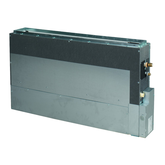
- Page 1 INSTALLATION MANUAL R410A Split series FNQ25A2VEB FNQ35A2VEB FNQ50A2VEB FNQ60A2VEB...
- Page 2 3P323721-7J...
-
Page 3: Table Of Contents
CONTENTS SAFETY PRECAUTIONS............1 ACCESSORIES . -
Page 4: Accessories
• During installation, attach the refrigerant piping securely before running the compressor. If the compressor is not attached and the shut-off valve is open during pump-down, air will be sucked in when the compressor is run, causing abnormal pressure in the freezer cycle which will lead to breakage and even injury. •... -
Page 5: Selecting Installation Site
ACCESSORIES a. Items to be checked after completion of work b. Items to be checked at time of delivery Items to be checked If not properly done, Check Items to be checked Check what is likely to occur Are the indoor and outdoor unit fixed firmly? The units may drop, Did you explain about operations while vibrate or make noise. -
Page 6: Preparations Before Installation
SELECTING INSTALLATION SITE Use suspension bolts to install the unit. Check whether or not the wall/floor is strong enough to support the weight of the unit. If there is a risk that it is not strong enough, reinforce the wall/floor before installing the unit. •... -
Page 7: Indoor Unit Installation
PREPARATIONS BEFORE INSTALLATION Removing the legs If it is necessary to remove the legs, follow these instructions: • In case of bottom suction 1) Remove the air filter 2) Unscrew 4 screws which hold both legs on the bottom side of the unit (see left picture below) 3) Unscrew 2 screws on the side of the unit and remove legs (see right picture below) 4) Reattach the air filter •... - Page 8 INDOOR UNIT INSTALLATION Mounting the remote controller Refer to the “installation manual of the remote controller” supplied with remote controller. Wall mounted type/floor standing concealed type The unit requires minimum 100mm clearance (F) and clearance (E) on the bottom side for air intake and maximum 20mm clearance from the wall by using spacers (field supply).
- Page 9 INDOOR UNIT INSTALLATION Wall mounted installation Floor standing concealed installation Install the unit according to the figures below. Install the unit according to the figures below. Unit of measurement = mm Unit of measurement = mm Unit Model 25/35 50/60 Width of air inlet grille 1060...
-
Page 10: Outdoor Unit Installation
OUTDOOR UNIT INSTALLATION Install as described in the installation manual supplied with the outdoor unit. REFRIGERANT PIPING WORK See the installation manual supplied with the outdoor unit. FLARING THE PIPE END 1) Cut the pipe end with a pipe cutter. 2) Remove burrs with the cut surface facing downward (Cut exactly at right angles.) Remove burrs... - Page 11 REFRIGERANT PIPING WORK Gas Piping Insulation Procedure Measure the length of the gas Liquid Piping Insulation Procedure pipe as you will have to cover it Insulation for fitting Insulation for fitting Piping insulation with the sealing tape. Piping insulation (accessory) (accessory) material (main unit) material (main unit)
-
Page 12: Drain Piping Work
DRAIN PIPING WORK Caution Make sure all water is out before making the duct connection. Install the drain piping. Refrigerant pipes • Make sure the drain works properly. • The diameter of the drain pipe should be greater than or equal to the diameter of the connecting pipe (vinyl tube;... -
Page 13: Installing The Duct
INSTALLING THE DUCT Connect the duct supplied in the field. Air inlet side • Attach the duct and intake-side flange (field supply). • Connect the flange to the main unit with accessory screws (in 16, 20 or 24 positions). • Wrap the intake-side flange and duct connection area with aluminum tape or something similar to prevent air escaping. Caution When attaching a duct to the intake side, be sure also to attach an air filter inside the air passage on the intake side. - Page 14 WIRING [ Connecting electrical wiring ] Power supply wiring and Earth wire Remove the control box lid. Next, pull the wires into the unit through the wiring through hole and connect to the power wiring terminal block (4P). Be sure to put the part of the sheathed vinyl into the control box. Control box Control box Transmission wiring / Remote contr.
-
Page 15: Wiring Diagram
WIRING DIAGRAM : FIELD WIRING : BLACK : PURPLE : CONNECTOR : BLUE : RED : WIRE CLAMP : BROWN : WHITE : GREY : YELLOW : PROTECTIVE EARTH (SCREW) : LIVE : ORANGE : GREEN : NEUTRAL : PINK INDOOR UNIT RECEIVER/DISPLAY UNIT A1P...... -
Page 16: Trial Operation And Testing
TRIAL OPERATION AND TESTING Trial operation and testing (1) Measure the supply voltage and make sure that it falls in the specified range. (2) Trial operation should be carried out in either cooling or heating mode. Trial operation from remote controller (1) Press ON/OFF button to turn on the system. - Page 20 4P393317-1 2014.12...