Advertisement
Quick Links
QUICK START GUIDE
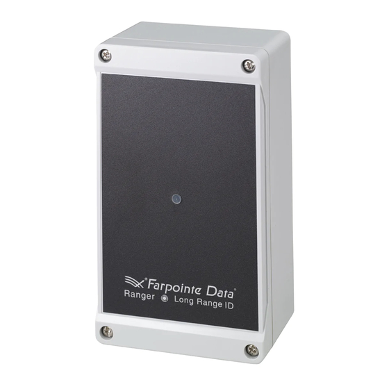
WRR-44-OSDP RANGER
433-MHz RECEIVER WITH OSDP SUPPORT
This Quick Start Guide is intended for experienced installing technicians. It is a basic reference to ensure all connections are properly made.
Installation and wiring of systems must be in accordance with the National Electrical Code, ANSI/NFPA 70.
1.0 Introduction
Long Range Transmitters and Receivers with an integrated receive
antenna comprise Farpointe Data's high frequency, long-range
identification solution known as Ranger. Intended for security access
control applications, Ranger's wireless communications are based
upon a secure, digital, anti-playback routine. The four-channel Ranger
Receiver (Channels A, B, C & D), model WRR-44-OSDP, allows Ranger
Transmitter data to be sent over four separate outputs. However, OSDP
is limited to Channel A. Formatting of the OSDP output is dependent
upon the data encoded on each individual Ranger Transmitter.
2.0 Receiver Layout
Legend:
a. Antenna Connector
b. Audio Beeper
c. 10-PIN Terminal Block
3.0 Cable Requirements
Cable, 22 or 24 AWG [65 mm or 51 mm] twisted pair, over-all shield
and UL approved (Belden 8273, or equivalent).
Maximum bus length: 4,000 ft – 24 AWG (1,219 m)
Maximum distance between: 1,640 ft – 24 AWG (500 m)
4.0 Output Formats
The SIA standard OSDP protocol is supported for clear and secure
channel communication.
Default Address: 0
Default Baud rate: 9600bps (bits per second)
Default Secure Channel Key:
SCBK_D = 0x303132333435363738393A3B3C3D3E3F.
OSDP Protocol Technical Support:
SIA OSDP Application Profile: Basic Reader (OSDP v2.2 and higher)
5.0 Grounding
Shield (drain) continuity must run from the Receiver to the access
panel. Further, the shield and Receiver ground must be tied together
at the access panel, and must connect to an earth ground at one
point only.
LONG-RANGE
®
d. Read Range Adjustment
e. Antenna Switch
f.
Beeper Switch
6.0 Power
Power required is 12 VDC nominal at 120 mA. The Receiver may be
powered by the access panel. A linear power supply is recommended
for best operation.
7.0 Mounting
The Receiver may be mounted indoors or outdoors. The base of
the enclosure includes a drill template providing mounting provisions
to a wall box (standard North American and European), as well as pre-
drilled holes in the four corners allowing mounting to a flat surface.
Use supplied #6 mounting screws, or equivalent security screws,
for installation.
8.0 Read Range Adjustment
As shipped, the Receiver is set for the maximum read range, which is
nominally up to 200 feet (61 m). For optimal read range, it is important
that the Receiver be mounted as far from potential interference sources
as possible. These sources may include, but are not limited to, large
metal and concrete obstructions, as well as magnetic fields and radio
transmissions. Further range varies based on the height a Receiver is
installed, how a user may hold a Transmitter when being used, and
where the Transmitter is being used. Read range may vary for each
installation. Read range may be reduced by gently adjusting the
Receiver's range pot in the counter-clockwise direction.
9.0 Read Mode
Reader (OSDP "PD") operation is controlled by the access panel
(OSDP "ACU") per the OSDP specification.
10.0 External LED Indicator
Refer to the information below for explanation on the Receiver's
external LED indicator operation:
LED State
Description
Green
Initial power up
Amber
Normal powered on state
Flash Green
An activated Transmitter button press has
been received and processed
Flash Red
A non-activated Transmitter button press
has been detected
Off
Receiver is not powered on, or failed to
power up successfully
11.0 Antenna Switch
As shipped, the Receiver's Antenna Switch is set in the INT (internal)
position. Read range can be extended using a separate, external
antenna attached to Receiver's on-board 6.19 mm SMA jack
connector. If a separate, external antenna is used, then the switch
should be set in the EXT (external) position. For installations requiring
a separate, external antenna, please refer to the WRR-44 External
Antenna Reference Document.
Advertisement

Summary of Contents for Farpointe Data RANGER WRR-44-OSDP
- Page 1 Long Range Transmitters and Receivers with an integrated receive Power required is 12 VDC nominal at 120 mA. The Receiver may be antenna comprise Farpointe Data’s high frequency, long-range powered by the access panel. A linear power supply is recommended identification solution known as Ranger.
- Page 2 , and CONEKT are the registered ® ® ® ® San Jose, CA 95131 USA U.S. trademarks of Farpointe Data, Inc. All other trademarks are the property Office: +1-408-731-8700 of their respective owners. Fax: +1-408-731-8705 support@farpointedata.com www.farpointedata.com Apr-16-2021 P/N: 01672-002 ∙ Rev. 1...


